2006 MERCEDES-BENZ SPRINTER automatic transmission fluid
[x] Cancel search: automatic transmission fluidPage 1889 of 2305
washer must align with the 3 raised pads (arrow) of
the B1 multiple-disc carrier (1). The cone of the
spring washer must point downwards.
(5) Insert the multiple-disc pack (6) in the outer
multiple-disc carrier and measure the clutch clear-
ance.
NOTE: Pay attention to the sequence of discs. If the
original clutch discs are reused, be sure to return
the disc identified on disassembly as belonging on
top of the disc spring (5) to its original location.
CAUTION: When working with double sided friction
discs, an externally lugged steel plate is installed
first, followed by a friction disc, and continuing on
until all the required discs are installed. When work-
ing with single sided friction discs, an externally
lugged disc is installed first, followed by an inter-
nally lugged disc, and continuing on until all the
required discs are installed. All single sided discs
are installed with the friction side up.
NOTE: Place new friction multiple-discs in ATF fluid
for one hour before installing.
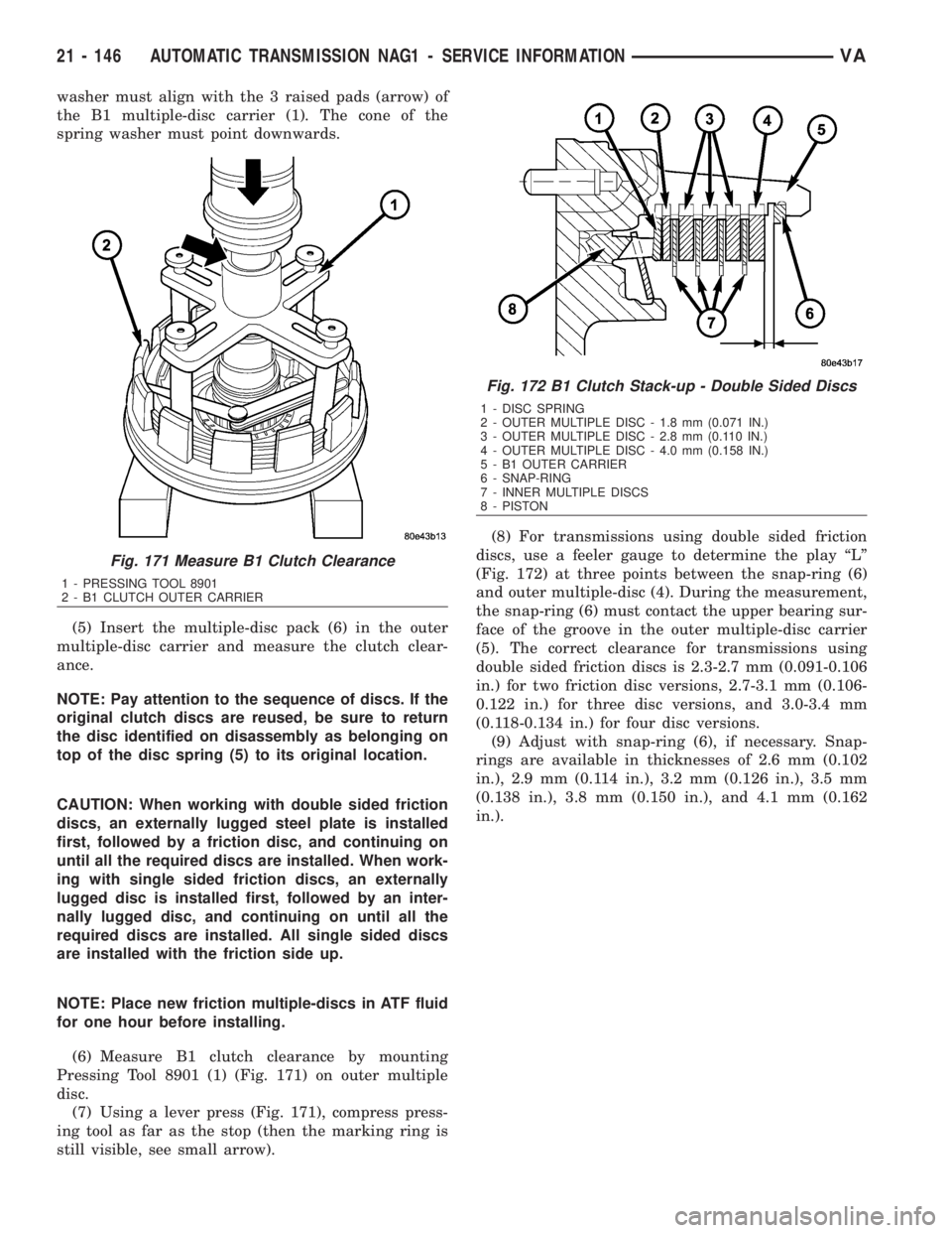
(6) Measure B1 clutch clearance by mounting
Pressing Tool 8901 (1) (Fig. 171) on outer multiple
disc.
(7) Using a lever press (Fig. 171), compress press-
ing tool as far as the stop (then the marking ring is
still visible, see small arrow).(8) For transmissions using double sided friction
discs, use a feeler gauge to determine the play ªLº
(Fig. 172) at three points between the snap-ring (6)
and outer multiple-disc (4). During the measurement,
the snap-ring (6) must contact the upper bearing sur-
face of the groove in the outer multiple-disc carrier
(5). The correct clearance for transmissions using
double sided friction discs is 2.3-2.7 mm (0.091-0.106
in.) for two friction disc versions, 2.7-3.1 mm (0.106-
0.122 in.) for three disc versions, and 3.0-3.4 mm
(0.118-0.134 in.) for four disc versions.
(9) Adjust with snap-ring (6), if necessary. Snap-
rings are available in thicknesses of 2.6 mm (0.102
in.), 2.9 mm (0.114 in.), 3.2 mm (0.126 in.), 3.5 mm
(0.138 in.), 3.8 mm (0.150 in.), and 4.1 mm (0.162
in.).
Fig. 171 Measure B1 Clutch Clearance
1 - PRESSING TOOL 8901
2 - B1 CLUTCH OUTER CARRIER
Fig. 172 B1 Clutch Stack-up - Double Sided Discs
1 - DISC SPRING
2 - OUTER MULTIPLE DISC - 1.8 mm (0.071 IN.)
3 - OUTER MULTIPLE DISC - 2.8 mm (0.110 IN.)
4 - OUTER MULTIPLE DISC - 4.0 mm (0.158 IN.)
5 - B1 OUTER CARRIER
6 - SNAP-RING
7 - INNER MULTIPLE DISCS
8 - PISTON
21 - 146 AUTOMATIC TRANSMISSION NAG1 - SERVICE INFORMATIONVA
Page 1895 of 2305
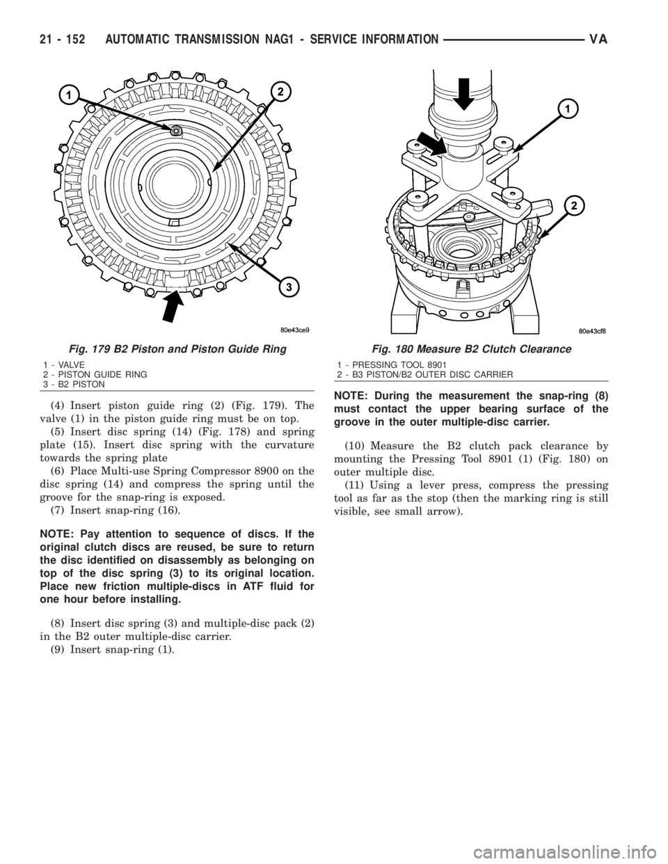
(4) Insert piston guide ring (2) (Fig. 179). The
valve (1) in the piston guide ring must be on top.
(5) Insert disc spring (14) (Fig. 178) and spring
plate (15). Insert disc spring with the curvature
towards the spring plate
(6) Place Multi-use Spring Compressor 8900 on the
disc spring (14) and compress the spring until the
groove for the snap-ring is exposed.
(7) Insert snap-ring (16).
NOTE: Pay attention to sequence of discs. If the
original clutch discs are reused, be sure to return
the disc identified on disassembly as belonging on
top of the disc spring (3) to its original location.
Place new friction multiple-discs in ATF fluid for
one hour before installing.
(8) Insert disc spring (3) and multiple-disc pack (2)
in the B2 outer multiple-disc carrier.
(9) Insert snap-ring (1).NOTE: During the measurement the snap-ring (8)
must contact the upper bearing surface of the
groove in the outer multiple-disc carrier.
(10) Measure the B2 clutch pack clearance by
mounting the Pressing Tool 8901 (1) (Fig. 180) on
outer multiple disc.
(11) Using a lever press, compress the pressing
tool as far as the stop (then the marking ring is still
visible, see small arrow).
Fig. 179 B2 Piston and Piston Guide Ring
1 - VALVE
2 - PISTON GUIDE RING
3 - B2 PISTON
Fig. 180 Measure B2 Clutch Clearance
1 - PRESSING TOOL 8901
2 - B3 PISTON/B2 OUTER DISC CARRIER
21 - 152 AUTOMATIC TRANSMISSION NAG1 - SERVICE INFORMATIONVA
Page 1906 of 2305
(9) Verify repair.
PISTONS
DESCRIPTION
There are several sizes and types of pistons used in
an automatic transmission. Some pistons are used to
apply clutches. They all have in common the fact
that they are round or circular in shape, located
within a smooth walled cylinder, which is closed at
one end and converts fluid pressure into mechanical
movement. The fluid pressure exerted on the piston
is contained within the system through the use of
piston rings or seals.
OPERATION
The principal which makes this operation possible
is known as Pascal's Law. Pascal's Law can be stated
as: ªPressure on a confined fluid is transmitted
equally in all directions and acts with equal force on
equal areas.º
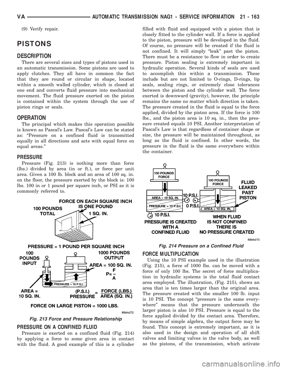
PRESSURE
Pressure (Fig. 213) is nothing more than force
(lbs.) divided by area (in or ft.), or force per unit
area. Given a 100 lb. block and an area of 100 sq. in.
on the floor, the pressure exerted by the block is: 100
lbs. 100 in or 1 pound per square inch, or PSI as it is
commonly referred to.
PRESSURE ON A CONFINED FLUID
Pressure is exerted on a confined fluid (Fig. 214)
by applying a force to some given area in contact
with the fluid. A good example of this is a cylinderfilled with fluid and equipped with a piston that is
closely fitted to the cylinder wall. If a force is applied
to the piston, pressure will be developed in the fluid.
Of course, no pressure will be created if the fluid is
not confined. It will simply ªleakº past the piston.
There must be a resistance to flow in order to create
pressure. Piston sealing is extremely important in
hydraulic operation. Several kinds of seals are used
to accomplish this within a transmission. These
include but are not limited to O-rings, D-rings, lip
seals, sealing rings, or extremely close tolerances
between the piston and the cylinder wall. The force
exerted is downward (gravity), however, the principle
remains the same no matter which direction is taken.
The pressure created in the fluid is equal to the force
applied, divided by the piston area. If the force is 100
lbs., and the piston area is 10 sq. in., then the pres-
sure created equals 10 PSI. Another interpretation of
Pascal's Law is that regardless of container shape or
size, the pressure will be maintained throughout, as
long as the fluid is confined. In other words, the
pressure in the fluid is the same everywhere within
the container.
FORCE MULTIPLICATION
Using the 10 PSI example used in the illustration
(Fig. 215), a force of 1000 lbs. can be moved with a
force of only 100 lbs. The secret of force multiplica-
tion in hydraulic systems is the total fluid contact
area employed. The illustration, (Fig. 215), shows an
area that is ten times larger than the original area.
The pressure created with the smaller 100 lb. input
is 10 PSI. The concept ªpressure is the same every-
whereº means that the pressure underneath the
larger piston is also 10 PSI. Pressure is equal to the
force applied divided by the contact area. Therefore,
by means of simple algebra, the output force may be
found. This concept is extremely important, as it is
also used in the design and operation of all shift
valves and limiting valves in the valve body, as well
as the pistons, of the transmission, which activate
Fig. 213 Force and Pressure Relationship
Fig. 214 Pressure on a Confined Fluid
VAAUTOMATIC TRANSMISSION NAG1 - SERVICE INFORMATION 21 - 163
Page 1917 of 2305
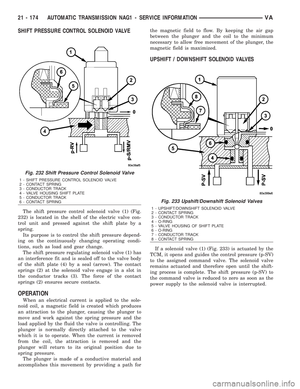
SHIFT PRESSURE CONTROL SOLENOID VALVE
The shift pressure control solenoid valve (1) (Fig.
232) is located in the shell of the electric valve con-
trol unit and pressed against the shift plate by a
spring.
Its purpose is to control the shift pressure depend-
ing on the continuously changing operating condi-
tions, such as load and gear change.
The shift pressure regulating solenoid valve (1) has
an interference fit and is sealed off to the valve body
of the shift plate (4) by a seal (arrow). The contact
springs (2) at the solenoid valve engage in a slot in
the conductor tracks (3). The force of the contact
springs (2) ensures secure contacts.
OPERATION
When an electrical current is applied to the sole-
noid coil, a magnetic field is created which produces
an attraction to the plunger, causing the plunger to
move and work against the spring pressure and the
load applied by the fluid the valve is controlling. The
plunger is normally directly attached to the valve
which it is to operate. When the current is removed
from the coil, the attraction is removed and the
plunger will return to its original position due to
spring pressure.
The plunger is made of a conductive material and
accomplishes this movement by providing a path forthe magnetic field to flow. By keeping the air gap
between the plunger and the coil to the minimum
necessary to allow free movement of the plunger, the
magnetic field is maximized.
UPSHIFT / DOWNSHIFT SOLENOID VALVES
If a solenoid valve (1) (Fig. 233) is actuated by the
TCM, it opens and guides the control pressure (p-SV)
to the assigned command valve. The solenoid valve
remains actuated and therefore open until the shift-
ing process is complete. The shift pressure (p-SV) to
the command valve is reduced to zero as soon as the
power supply to the solenoid valve is interrupted.
Fig. 232 Shift Pressure Control Solenoid Valve
1 - SHIFT PRESSURE CONTROL SOLENOID VALVE
2 - CONTACT SPRING
3 - CONDUCTOR TRACK
4 - VALVE HOUSING SHIFT PLATE
5 - CONDUCTOR TRACK
6 - CONTACT SPRING
Fig. 233 Upshift/Downshift Solenoid Valves
1 - UPSHIFT/DOWNSHIFT SOLENOID VALVE
2 - CONTACT SPRING
3 - CONDUCTOR TRACK
4 - O-RING
5 - VALVE HOUSING OF SHIFT PLATE
6 - O-RING
7 - CONDUCTOR TRACK
8 - CONTACT SPRING
21 - 174 AUTOMATIC TRANSMISSION NAG1 - SERVICE INFORMATIONVA
Page 1921 of 2305
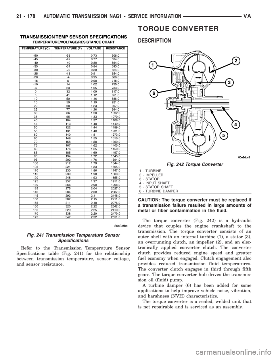
Refer to the Transmission Temperature Sensor
Specifications table (Fig. 241) for the relationship
between transmission temperature, sensor voltage,
and sensor resistance.
TORQUE CONVERTER
DESCRIPTION
CAUTION: The torque converter must be replaced if
a transmission failure resulted in large amounts of
metal or fiber contamination in the fluid.
The torque converter (Fig. 242) is a hydraulic
device that couples the engine crankshaft to the
transmission. The torque converter consists of an
outer shell with an internal turbine (1), a stator (3),
an overrunning clutch, an impeller (2), and an elec-
tronically applied converter clutch. The converter
clutch provides reduced engine speed and greater
fuel economy when engaged. Clutch engagement also
provides reduced transmission fluid temperatures.
The converter clutch engages in third through fifth
gears. The torque converter hub drives the transmis-
sion oil (fluid) pump.
A turbine damper (6) has been added for some
applications to help improve vehicle noise, vibration,
and harshness (NVH) characteristics.
The torque converter is a sealed, welded unit that
is not repairable and is serviced as an assembly.
Fig. 241 Transmission Temperature Sensor
Specifications
Fig. 242 Torque Converter
1 - TURBINE
2 - IMPELLER
3-STATOR
4 - INPUT SHAFT
5 - STATOR SHAFT
6 - TURBINE DAMPER
21 - 178 AUTOMATIC TRANSMISSION NAG1 - SERVICE INFORMATIONVA
Page 1924 of 2305
STATOR
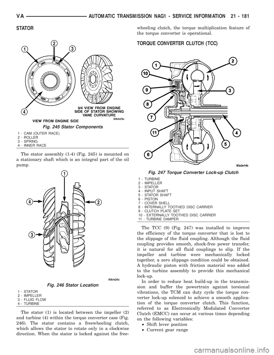
The stator assembly (1-4) (Fig. 245) is mounted on
a stationary shaft which is an integral part of the oil
pump.
The stator (1) is located between the impeller (2)
and turbine (4) within the torque converter case (Fig.
246). The stator contains a freewheeling clutch,
which allows the stator to rotate only in a clockwise
direction. When the stator is locked against the free-wheeling clutch, the torque multiplication feature of
the torque converter is operational.
TORQUE CONVERTER CLUTCH (TCC)
The TCC (9) (Fig. 247) was installed to improve
the efficiency of the torque converter that is lost to
the slippage of the fluid coupling. Although the fluid
coupling provides smooth, shock-free power transfer,
it is natural for all fluid couplings to slip. If the
impeller and turbine were mechanically locked
together, a zero slippage condition could be obtained.
A hydraulic piston with friction material was added
to the turbine assembly to provide this mechanical
lock-up.
In order to reduce heat build-up in the transmis-
sion and buffer the powertrain against torsional
vibrations, the TCM can duty cycle the torque con-
verter lock-up solenoid to achieve a smooth applica-
tion of the torque converter clutch. This function,
referred to as Electronically Modulated Converter
Clutch (EMCC) can occur at various times depending
on the following variables:
²Shift lever position
²Current gear range
Fig. 245 Stator Components
1 - CAM (OUTER RACE)
2 - ROLLER
3 - SPRING
4 - INNER RACE
Fig. 246 Stator Location
1-STATOR
2 - IMPELLER
3 - FLUID FLOW
4 - TURBINE
Fig. 247 Torque Converter Lock-up Clutch
1 - TURBINE
2 - IMPELLER
3-STATOR
4 - INPUT SHAFT
5 - STATOR SHAFT
6 - PISTON
7 - COVER SHELL
8 - INTERNALLY TOOTHED DISC CARRIER
9 - CLUTCH PLATE SET
10 - EXTERNALLY TOOTHED DISC CARRIER
11 - TURBINE DAMPER
VAAUTOMATIC TRANSMISSION NAG1 - SERVICE INFORMATION 21 - 181
Page 1925 of 2305
²Transmission fluid temperature
²Engine coolant temperature
²Input speed
²Throttle angle
²Engine speed
OPERATION
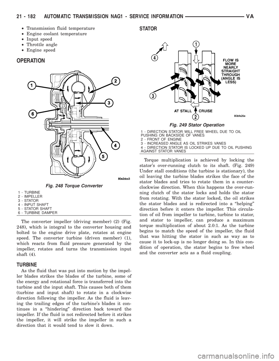
The converter impeller (driving member) (2) (Fig.
248), which is integral to the converter housing and
bolted to the engine drive plate, rotates at engine
speed. The converter turbine (driven member) (1),
which reacts from fluid pressure generated by the
impeller, rotates and turns the transmission input
shaft (4).
TURBINE
As the fluid that was put into motion by the impel-
ler blades strikes the blades of the turbine, some of
the energy and rotational force is transferred into the
turbine and the input shaft. This causes both of them
(turbine and input shaft) to rotate in a clockwise
direction following the impeller. As the fluid is leav-
ing the trailing edges of the turbine's blades it con-
tinues in a ªhinderingº direction back toward the
impeller. If the fluid is not redirected before it strikes
the impeller, it will strike the impeller in such a
direction that it would tend to slow it down.
STATOR
Torque multiplication is achieved by locking the
stator's over-running clutch to its shaft. (Fig. 249)
Under stall conditions (the turbine is stationary), the
oil leaving the turbine blades strikes the face of the
stator blades and tries to rotate them in a counter-
clockwise direction. When this happens the over-run-
ning clutch of the stator locks and holds the stator
from rotating. With the stator locked, the oil strikes
the stator blades and is redirected into a ªhelpingº
direction before it enters the impeller. This circula-
tion of oil from impeller to turbine, turbine to stator,
and stator to impeller, can produce a maximum
torque multiplication of about 2.0:1. As the turbine
begins to match the speed of the impeller, the fluid
that was hitting the stator in such as way as to
cause it to lock-up is no longer doing so. In this con-
dition of operation, the stator begins to free wheel
and the converter acts as a fluid coupling.
Fig. 248 Torque Converter
1 - TURBINE
2 - IMPELLER
3-STATOR
4 - INPUT SHAFT
5 - STATOR SHAFT
6 - TURBINE DAMPER
Fig. 249 Stator Operation
1 - DIRECTION STATOR WILL FREE WHEEL DUE TO OIL
PUSHING ON BACKSIDE OF VANES
2 - FRONT OF ENGINE
3 - INCREASED ANGLE AS OIL STRIKES VANES
4 - DIRECTION STATOR IS LOCKED UP DUE TO OIL PUSHING
AGAINST STATOR VANES
21 - 182 AUTOMATIC TRANSMISSION NAG1 - SERVICE INFORMATIONVA
Page 1927 of 2305
INSTALLATION
Check converter hub and drive flats for sharp
edges, burrs, scratches, or nicks. Polish the hub and
flats with 320/400 grit paper or crocus cloth if neces-
sary. The hub must be smooth to avoid damaging the
pump seal at installation.
(1) Lubricate oil pump seal lip with transmission
fluid.
(2)
Place torque converter in position on transmission.
CAUTION: Do not damage oil pump seal or con-
verter hub while inserting torque converter into the
front of the transmission.
(3) Align torque converter to oil pump seal open-
ing.
(4) Insert torque converter hub into oil pump.
(5) While pushing torque converter inward, rotate
converter until converter is fully seated in the oil
pump gears.
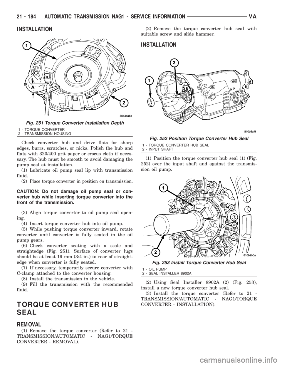
(6) Check converter seating with a scale and
straightedge (Fig. 251). Surface of converter lugs
should be at least 19 mm (3/4 in.) to rear of straight-
edge when converter is fully seated.
(7) If necessary, temporarily secure converter with
C-clamp attached to the converter housing.
(8) Install the transmission in the vehicle.
(9) Fill the transmission with the recommended
fluid.
TORQUE CONVERTER HUB
SEAL
REMOVAL
(1) Remove the torque converter (Refer to 21 -
TRANSMISSION/AUTOMATIC - NAG1/TORQUE
CONVERTER - REMOVAL).(2) Remove the torque converter hub seal with
suitable screw and slide hammer.
INSTALLATION
(1) Position the torque converter hub seal (1) (Fig.
252) over the input shaft and against the transmis-
sion oil pump.
(2) Using Seal Installer 8902A (2) (Fig. 253),
install a new torque converter hub seal.
(3) Install the torque converter (Refer to 21 -
TRANSMISSION/AUTOMATIC - NAG1/TORQUE
CONVERTER - INSTALLATION).
Fig. 251 Torque Converter Installation Depth
1 - TORQUE CONVERTER
2 - TRANSMISSION HOUSING
Fig. 252 Position Torque Converter Hub Seal
1 - TORQUE CONVERTER HUB SEAL
2 - INPUT SHAFT
Fig. 253 Install Torque Converter Hub Seal
1 - OIL PUMP
2 - SEAL INSTALLER 8902A
21 - 184 AUTOMATIC TRANSMISSION NAG1 - SERVICE INFORMATIONVA