2006 MERCEDES-BENZ SPRINTER ignition
[x] Cancel search: ignitionPage 426 of 2305

3.2.6 SKREEM OPERATION
When ignition power is supplied to the SKREEM,
the SKREEM performs an internal self-test. After
the self-test is complete, the SKREEM energizes
the antenna (this activates the transponder chip)
and sends a challenge to the transponder chip. The
transponder chip responds to the challenge by gen-
erating an encrypted response message.
After responding to the coded message, the tran-
sponder sends a transponder ID message to the
SKREEM. The SKREEM compares the transpon-
der ID message to the available valid key codes in
SKREEM memory (8 key maximum at any one
time). After validating the ignition key the
SKREEM sends a CAN Bus message request to the
ECM, then waits for the ECM response. If the ECM
does not respond, the SKREEM will send the re-
quest again. If the ECM does not respond again, the
SKREEM will stop sending the request and store a
trouble code in memory. If the ECM sends a correct
response to the SKREEM, the SKREEM sends a
valid/invalid key message to the ECM. The ECM
will allow or disallow engine operation based on this
message.
Secret Key - an electronically stored value (iden-
tification number) that is unique to each SKREEM.
The secret key is stored in the SKREEM, ECM and
all ignition key transponders.
Challenge - a random number that is generated by
the SKREEM at each ignition key cycle.
The secret key and challenge are the two vari-
ables used in the algorithm that produces the
encrypted response message. The transponder uses
the crypto algorithm to receive, decode and respond
to the message sent by the SKREEM. After re-
sponding to the coded message, the transponder
sends a transponder ID message to the SKREEM.
3.3 DIAGNOSTIC TROUBLE CODES
Each diagnostic trouble code (DTC) is diagnosed
by following a specific procedure. The diagnostic
test procedure contains step-by-step instruction for
determining the cause of the DTC as well as no
trouble code problems. It is not necessary to per-
form all of the tests in this book to diagnose an
individual code.
Always begin diagnosis by reading the DTCs
using the DRBIIIt. This will direct you to the
specific test(s) that must be performed.
3.3.1 HARD CODE
A DTC that comes back within one cycle of the
ignition key is a hard code. This means that the
problem is current every time the ECM/SKREEM
checks that circuit or function. Procedures in this
manual verify if the DTC is a hard code at thebeginning of each test. When the fault is not a hard
code, an intermittent test must be performed.
NOTE: If the DRBIIITdisplays faults for
multiple components (i.e. ECT, MAF, IAT
sensors) identify and check the shared
circuits for possible problems before
continuing (i.e. sensor grounds or 5-volt
supply circuits). Refer to the appropriate
schematic to identify shared circuits.
3.3.2 INTERMITTENT CODE
A DTC that is not current every time the ECM/
SKREEM checks the circuit or function is an inter-
mittent code. Most intermittent DTCs are caused
by wiring or connector problems. Problems that
come and go like this are the most difficult to
diagnose; they must be looked for under specific
conditions that cause them. The following checks
may assist you in identifying a possible intermit-
tent problem.
± Visually inspect the related wire harness con-
nectors. Look for broken, bent, pushed out or
corroded terminals.
± Visually inspect the related wire harness.
Look for chafed, pierced or partially broken
wire.
± Refer to hotlines or technical service bulletins
that may apply.
NOTE: Electromagnetic (radio) interference
can cause an intermittent system
malfunction. This interference can interrupt
communication between the ignition key
transponder and the SKREEM.
3.3.3 ECM DIAGNOSTIC TROUBLE CODES
IMPORTANT NOTE: Before replacing the
ECM for a failed driver, control circuit or
ground circuit, be sure to check the related
component/circuit integrity for failures not
detected due to a double fault in the circuit.
Most ECM driver/control circuit failures are
caused by internal failures to components
(i.e. relays and solenoids) and shorted
circuits (i.e. sensor pull-ups, drivers and
ground circuits). These faults are difficult to
detect when a double fault has occurred and
only one DTC has set.
If the DRBIIItdisplays faults for multiple com-
ponents (i.e. MAF, ECT, ENG OIL, etc.), identify
and check the shared circuits for possible problems
before continuing (i.e. sensor grounds or 5-volt
3
GENERAL INFORMATION
Page 429 of 2305

fuel rail pressure malfunction rail pressure too high
fuel rail pressure malfunction rail pressure too low
fuel temperature sensor circuit signal voltage too
high
fuel temperature sensor circuit signal voltage too
low
fuel temperature sensor plausibility
general leakage
glow plug #1 circuit excessive current
glow plug #1 circuit open circuit
glow plug #1 circuit short to ground
glow plug #1 circuit short to voltage
glow plug #2 circuit excessive current
glow plug #2 circuit open circuit
glow plug #2 circuit short to ground
glow plug #2 circuit short to voltage
glow plug #3 circuit excessive current
glow plug #3 circuit open circuit
glow plug #3 circuit short to ground
glow plug #3 circuit short to voltage
glow plug #4 circuit excessive current
glow plug #4 circuit open circuit
glow plug #4 circuit short to ground
glow plug #4 circuit short to voltage
glow plug #5 circuit excessive current
glow plug #5 circuit open circuit
glow plug #5 circuit short to ground
glow plug #5 circuit short to voltage
glow plug control circuit preglow fault
glow plug control circuit preglow short to ground
glow plug control circuit preglow short to voltage
glow plug control module circuit open circuit
glow plug control module circuit shorted to ground
glow plug control module circuit shorted to voltage
or open
glow plug control module fault
glow plug indicator error
glow plug module communication error
glow plug module -communication error
glow plug module -excess current
glow plug module excessive current error
glow plug module -incorrect timer
glow plug module -internal fault
glow plug module timer error
ignition voltage -voltage error
immobilizer
immobilizer
immobilizer
immobilizer
immobilizer can message error
improper start attempt
injection fault excessive engine speed
injection fault -excessive temperature
injection fault -quantity error
injection fault -torque limit
injector 1 injection time above limit
injector 1 injection time below limit
injector 2 injection time above limitinjector 2 injection time below limit
injector 3 injection time above limit
injector 3 injection time below limit
injector 4 injection time above limit
injector 4 injection time below limit
injector 5 injection time above limit
injector 5 injection time below limit
injector bank error
injector bank error
injector circuit fault
injector circuit fault
injector circuit low side shorted to ground
injector circuit low side shorted to ground
injector circuit shorted to ground or voltage
injector circuit shorted to ground or voltage
instrument cluster message -ambient temperature
signal plausibility
instrument cluster message plausibility
intake air temp sensor circuit signal voltage too high
intake air temp sensor circuit signal voltage too low
intake air temp sensor signal voltage too high
intake air temp sensor signal voltage too low
intake pressure sensor can message error
intake pressure sensor circuit fault
intake pressure sensor intake restriction
intake pressure sensor open circuit
intake pressure sensor plausibility
intake pressure sensor plausibility
intake pressure sensor signal voltage too high
intake pressure sensor signal voltage too high
intake pressure sensor signal voltage too high
intake pressure sensor signal voltage too low
intake pressure sensor signal voltage too low
intake pressure sensor signal voltage too low
internal error counter fault
internal error engine shut off
internal error engine voltage monitoring
internal error engine voltage monitoring
internal voltage error
kickdown switch plausibility
lateral accelerator sensor plausibilty
leakage cylinder #1
leakage cylinder #2
leakage cylinder #3
leakage cylinder #4
leakage cylinder #5
maf sensor signal plausibility
manual transmissio coded as auto transmission
mass air flow sensor negative deviation
mass air flow sensor plausibility
mass air flow sensor plausibility air mass too high
mass air flow sensor plausibility air mass too high
mass air flow sensor plausibility air mass too low
mass air flow sensor plausibility air mass too low
mass air flow sensor plausibility signal ratio error
mass air flow sensor plausibility signal ratio too
large
mass air flow sensor plausibility signal ratio too
6
GENERAL INFORMATION
Page 432 of 2305

service manual. Following these procedures is very
important to the safety of the individuals perform-
ing the diagnostic tests.
4.2.2 VEHICLE PREPARATION FOR
TESTING
Make sure the vehicle being tested has a fully
charged battery. If it does not, false diagnostic codes
or error messages may occur.
4.2.3 SERVICING SUB-ASSEMBLIES
Some components of the powertrain system are
intended to be serviced as an assembly only. At-
tempting to remove or repair certain system sub-
components may result in personal injury and/or
improper system operation. Only those components
with approved repair and installation procedures in
the service manual should be serviced.
4.2.4 DRBIIITSAFETY INFORMATION
WARNING: EXCEEDING THE LIMITS OF THE
DRBIIITMULTIMETER IS DANGEROUS. IT
CAN EXPOSE YOU TO SERIOUS OR
POSSIBLE FATAL INJURY. CAREFULLY
READ AND UNDERSTAND THE CAUTIONS
AND SPECIFICATION LIMITS.
Follow the vehicle manufacturer 's service specifi-
cations at all times.
± Do not use the DRBIIItif it has been dam-
aged.
± Do not use the test leads if the insulation is
damaged or if metal is exposed.
± To avoid electrical shock, do not touch the test
leads, tip or the circuit being tested.
± Choose the proper range and function for the
measurement. Do not try voltage or current
measurements that may exceed the rated ca-
pacity.
± Do not exceed the limits shown in the table
below:
FUNCTION INPUT LIMIT
Volts 0±500 peak volts AC
0±500 volts DC
Ohms (Resistance)* 0±1.12 megaohms
Frequency Measure
Frequency Generated0±10 kHz
Temperature ±58 ± +1100ÉF
±50 ± +600ÉC
* Ohms cannot be measured if voltage is present.
Ohms can be measured only on a non-powered
circuit.± Voltage between any terminal and ground
must not exceed 500v DC or 500v peak AC.
± Use caution when measuring voltage above
25v DC or 25v AC.
± The circuit being tested must be protected by a
10 amp fuse or circuit breaker.
± Use the low current shunt to measure circuits
up to 10 amps. Use the high current shunt to
measure circuits exceeding 10 amps.
± When testing for the presence of voltage or
current, make sure the meter is functioning
correctly. Take a reading of a known voltage or
current before accepting a zero reading.
± When measuring current, connect the meter in
series with the load.
± Disconnect the live test lead before disconnect-
ing the common test lead.
4.3 WARNINGS AND CAUTIONS
4.3.1 ROAD TEST WARNINGS
Some complaints will require a test drive as part
of the repair verification procedure. The purpose of
the test drive is to try to duplicate the diagnostic
code or symptom condition.
CAUTION: Before road testing a vehicle, be
sure that all components are reassembled.
During the test drive, do not hang the DRBIIIT
from the rear view mirror. Do not attempt to
read the DRBIIITwhile driving. Have an
assistant available to operate the DRBIIIT.
4.3.2 VEHICLE DAMAGE CAUTIONS
Before disconnecting any control module, make
sure the ignition is off. Failure to do so could
damage the module. When testing voltage or circuit
integrity at any control module, use the terminal
side (not the wire end) of the harness connector. Do
not probe through the insulation; this will damage
it and eventually cause it to fail because of corro-
sion.
Be careful when performing electrical test so as to
prevent accidental shorting of terminals. Such a
mistake can damage fuses or components. Also, a
second code could be set, making diagnosis of the
original problem more difficult.
5.0 REQUIRED TOOLS AND
EQUIPMENT
DRBIIIt(diagnostic read-out box) scan tool
vacuum gauge
ammeter
9
GENERAL INFORMATION
Page 435 of 2305

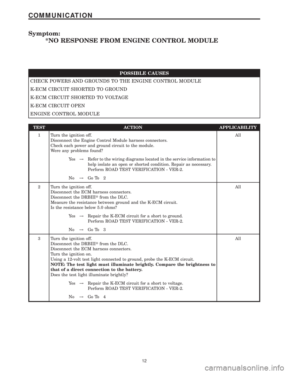
Symptom:
*NO RESPONSE FROM ENGINE CONTROL MODULE
POSSIBLE CAUSES
CHECK POWERS AND GROUNDS TO THE ENGINE CONTROL MODULE
K-ECM CIRCUIT SHORTED TO GROUND
K-ECM CIRCUIT SHORTED TO VOLTAGE
K-ECM CIRCUIT OPEN
ENGINE CONTROL MODULE
TEST ACTION APPLICABILITY
1 Turn the ignition off.
Disconnect the Engine Control Module harness connectors.
Check each power and ground circuit to the module.
Were any problems found?All
Ye s!Refer to the wiring diagrams located in the service information to
help isolate an open or shorted condition. Repair as necessary.
Perform ROAD TEST VERIFICATION - VER-2.
No!Go To 2
2 Turn the ignition off.
Disconnect the ECM harness connectors.
Disconnect the DRBIIItfrom the DLC.
Measure the resistance between ground and the K-ECM circuit.
Is the resistance below 5.0 ohms?All
Ye s!Repair the K-ECM circuit for a short to ground.
Perform ROAD TEST VERIFICATION - VER-2.
No!Go To 3
3 Turn the ignition off.
Disconnect the DRBIIItfrom the DLC.
Disconnect the ECM harness connectors.
Turn the ignition on.
Using a 12-volt test light connected to ground, probe the K-ECM circuit.
NOTE: The test light must illuminate brightly. Compare the brightness to
that of a direct connection to the battery.
Does the test light illuminate brightly?All
Ye s!Repair the K-ECM circuit for a short to voltage.
Perform ROAD TEST VERIFICATION - VER-2.
No!Go To 4
12
COMMUNICATION
Page 436 of 2305

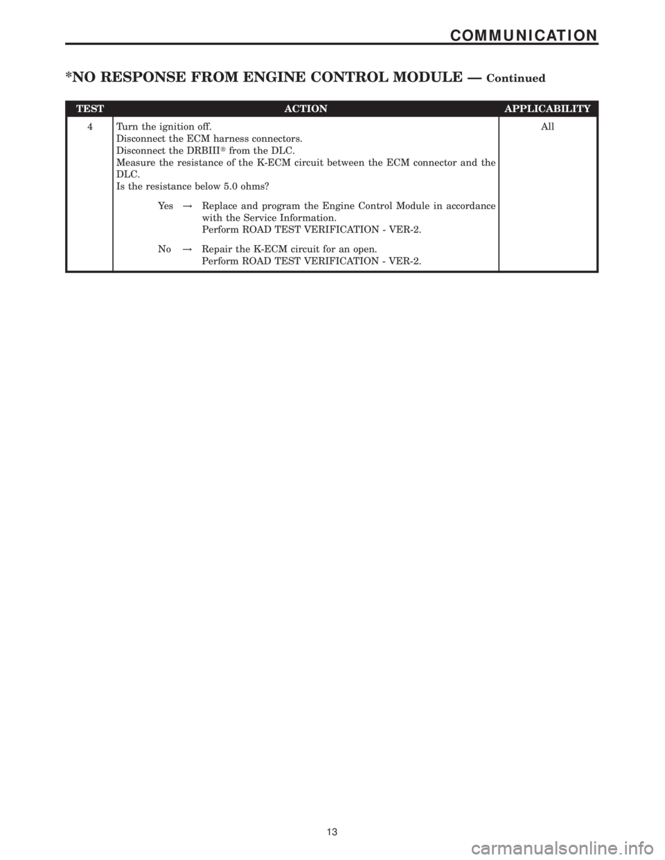
TEST ACTION APPLICABILITY
4 Turn the ignition off.
Disconnect the ECM harness connectors.
Disconnect the DRBIIItfrom the DLC.
Measure the resistance of the K-ECM circuit between the ECM connector and the
DLC.
Is the resistance below 5.0 ohms?All
Ye s!Replace and program the Engine Control Module in accordance
with the Service Information.
Perform ROAD TEST VERIFICATION - VER-2.
No!Repair the K-ECM circuit for an open.
Perform ROAD TEST VERIFICATION - VER-2.
13
COMMUNICATION
*NO RESPONSE FROM ENGINE CONTROL MODULE ÐContinued
Page 437 of 2305

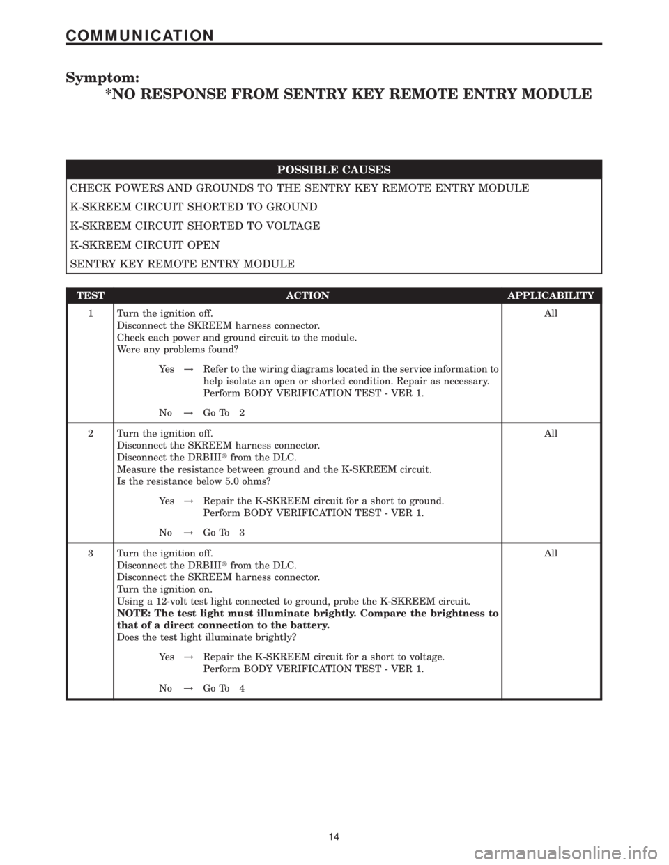
Symptom:
*NO RESPONSE FROM SENTRY KEY REMOTE ENTRY MODULE
POSSIBLE CAUSES
CHECK POWERS AND GROUNDS TO THE SENTRY KEY REMOTE ENTRY MODULE
K-SKREEM CIRCUIT SHORTED TO GROUND
K-SKREEM CIRCUIT SHORTED TO VOLTAGE
K-SKREEM CIRCUIT OPEN
SENTRY KEY REMOTE ENTRY MODULE
TEST ACTION APPLICABILITY
1 Turn the ignition off.
Disconnect the SKREEM harness connector.
Check each power and ground circuit to the module.
Were any problems found?All
Ye s!Refer to the wiring diagrams located in the service information to
help isolate an open or shorted condition. Repair as necessary.
Perform BODY VERIFICATION TEST - VER 1.
No!Go To 2
2 Turn the ignition off.
Disconnect the SKREEM harness connector.
Disconnect the DRBIIItfrom the DLC.
Measure the resistance between ground and the K-SKREEM circuit.
Is the resistance below 5.0 ohms?All
Ye s!Repair the K-SKREEM circuit for a short to ground.
Perform BODY VERIFICATION TEST - VER 1.
No!Go To 3
3 Turn the ignition off.
Disconnect the DRBIIItfrom the DLC.
Disconnect the SKREEM harness connector.
Turn the ignition on.
Using a 12-volt test light connected to ground, probe the K-SKREEM circuit.
NOTE: The test light must illuminate brightly. Compare the brightness to
that of a direct connection to the battery.
Does the test light illuminate brightly?All
Ye s!Repair the K-SKREEM circuit for a short to voltage.
Perform BODY VERIFICATION TEST - VER 1.
No!Go To 4
14
COMMUNICATION
Page 438 of 2305

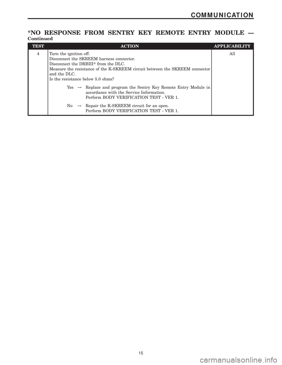
TEST ACTION APPLICABILITY
4 Turn the ignition off.
Disconnect the SKREEM harness connector.
Disconnect the DRBIIItfrom the DLC.
Measure the resistance of the K-SKREEM circuit between the SKREEM connector
and the DLC.
Is the resistance below 5.0 ohms?All
Ye s!Replace and program the Sentry Key Remote Entry Module in
accordance with the Service Information.
Perform BODY VERIFICATION TEST - VER 1.
No!Repair the K-SKREEM circuit for an open.
Perform BODY VERIFICATION TEST - VER 1.
15
COMMUNICATION
*NO RESPONSE FROM SENTRY KEY REMOTE ENTRY MODULE Ð
Continued
Page 440 of 2305

P2342-ECM INTERNAL ERROR 2
P2350-INTERNAL VOLTAGE ERROR
P2352-INJECTION FAULT - EXCESSIVE TEMPERATURE
P2352-INJECTION FAULT - QUANTITY ERROR
P2352-INJECTION FAULT - TORQUE LIMIT
P2352-INJECTION FAULT EXCESSIVE ENGINE SPEED
P2354-ECM INTERNAL FAULT
P2356-ECM INTERNAL ERROR
P2357-ECM INTERNAL ERROR
P2358-ECM INTERNAL ERROR
P2500-FUEL PRESSURE SOLENOID CIRCUIT EXCESSIVE CUR-
RENT
P2514-CRANKCASE VENT HEATER EXCESSIVE CURRENT
P2526-BOOST PRESSURE SERVO MOTOR EXCESSIVE CURRENT
P2527-EGR VALVE EXCESSIVE CURRENT
Test Note: All symptoms listed above are diagnosed using the same tests.
The title for the tests will be P-1105 ATMOSPHERIC PRES-
SURE SENSOR PLAUSIBILITY WITH BOOST PRESSURE
SENSOR.
When Monitored and Set Condition:
P1105-ATMOSPHERIC PRESSURE SENSOR SIGNAL VOLTAGE TOO HIGH
When Monitored: With the ignition on.
Set Condition: The ECM internal Atmospheric Pressure Sensor is faulty.
P1105-ATMOSPHERIC PRESSURE SENSOR SIGNAL VOLTAGE TOO LOW
When Monitored: With the ignition on.
Set Condition: The ECM internal Atmospheric Pressure Sensor is faulty.
P2500-FUEL PRESSURE SOLENOID CIRCUIT EXCESSIVE CURRENT
When Monitored: With the ignition on.
Set Condition: The ECM detects an open or short to ground on the Fuel Pressure Solenoid
Control circuit.
POSSIBLE CAUSES
ENGINE CONTROL MODULE
INTERMITTENT CONDITION
17
DRIVEABILITY - DIESEL
P-1105 ATMOSPHERIC PRESSURE SENSOR PLAUSIBILITY WITH
BOOST PRESSURE SENSOR Ð
Continued