2006 MERCEDES-BENZ SPRINTER check engine
[x] Cancel search: check enginePage 2180 of 2305
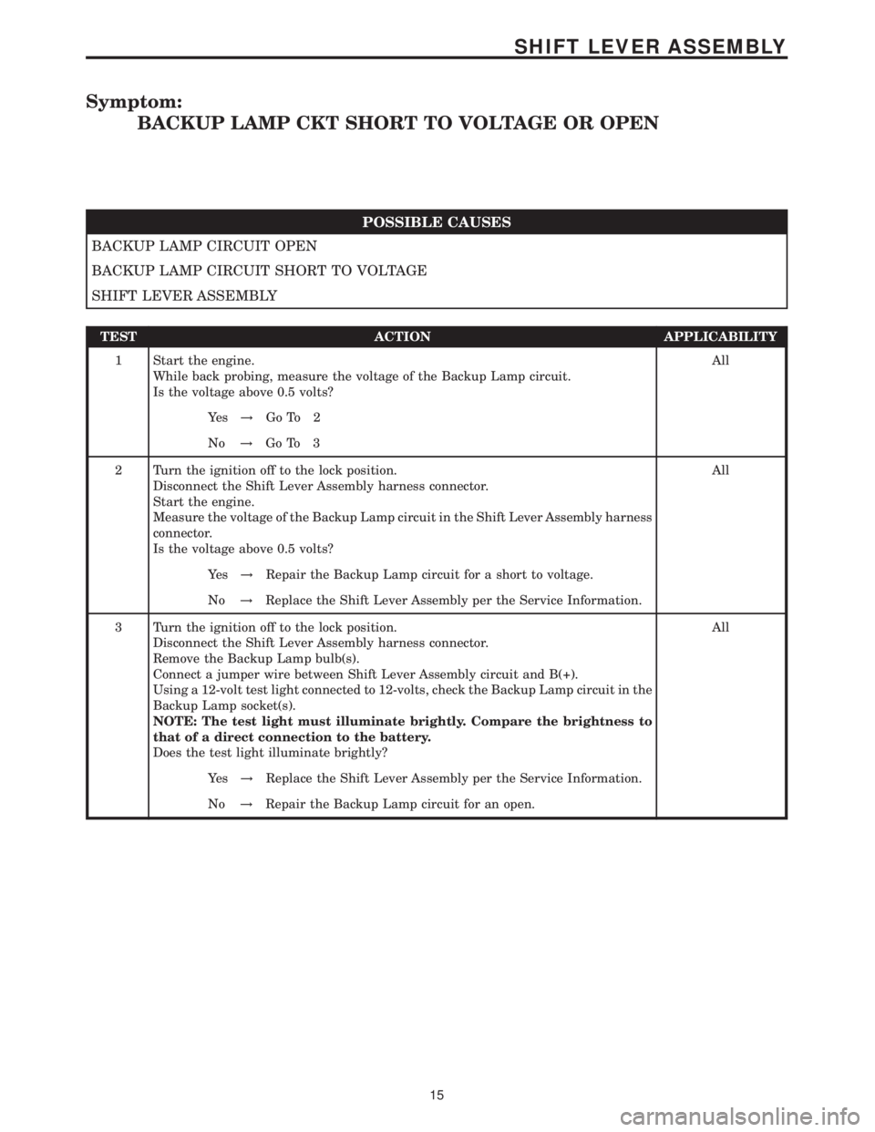
Symptom:
BACKUP LAMP CKT SHORT TO VOLTAGE OR OPEN
POSSIBLE CAUSES
BACKUP LAMP CIRCUIT OPEN
BACKUP LAMP CIRCUIT SHORT TO VOLTAGE
SHIFT LEVER ASSEMBLY
TEST ACTION APPLICABILITY
1 Start the engine.
While back probing, measure the voltage of the Backup Lamp circuit.
Is the voltage above 0.5 volts?All
Ye s!Go To 2
No!Go To 3
2 Turn the ignition off to the lock position.
Disconnect the Shift Lever Assembly harness connector.
Start the engine.
Measure the voltage of the Backup Lamp circuit in the Shift Lever Assembly harness
connector.
Is the voltage above 0.5 volts?All
Ye s!Repair the Backup Lamp circuit for a short to voltage.
No!Replace the Shift Lever Assembly per the Service Information.
3 Turn the ignition off to the lock position.
Disconnect the Shift Lever Assembly harness connector.
Remove the Backup Lamp bulb(s).
Connect a jumper wire between Shift Lever Assembly circuit and B(+).
Using a 12-volt test light connected to 12-volts, check the Backup Lamp circuit in the
Backup Lamp socket(s).
NOTE: The test light must illuminate brightly. Compare the brightness to
that of a direct connection to the battery.
Does the test light illuminate brightly?All
Ye s!Replace the Shift Lever Assembly per the Service Information.
No!Repair the Backup Lamp circuit for an open.
15
SHIFT LEVER ASSEMBLY
Page 2181 of 2305
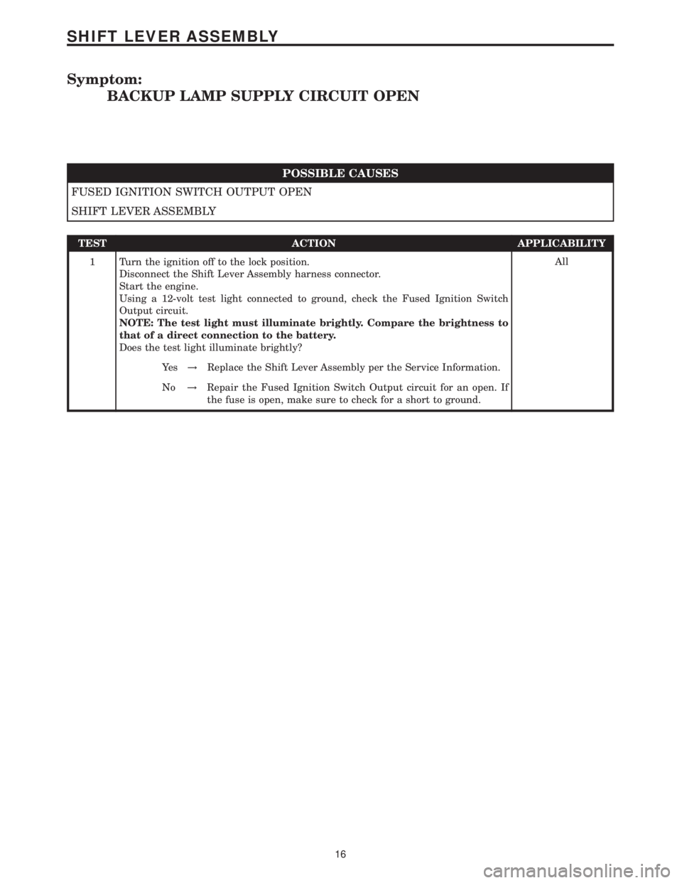
Symptom:
BACKUP LAMP SUPPLY CIRCUIT OPEN
POSSIBLE CAUSES
FUSED IGNITION SWITCH OUTPUT OPEN
SHIFT LEVER ASSEMBLY
TEST ACTION APPLICABILITY
1 Turn the ignition off to the lock position.
Disconnect the Shift Lever Assembly harness connector.
Start the engine.
Using a 12-volt test light connected to ground, check the Fused Ignition Switch
Output circuit.
NOTE: The test light must illuminate brightly. Compare the brightness to
that of a direct connection to the battery.
Does the test light illuminate brightly?All
Ye s!Replace the Shift Lever Assembly per the Service Information.
No!Repair the Fused Ignition Switch Output circuit for an open. If
the fuse is open, make sure to check for a short to ground.
16
SHIFT LEVER ASSEMBLY
Page 2186 of 2305
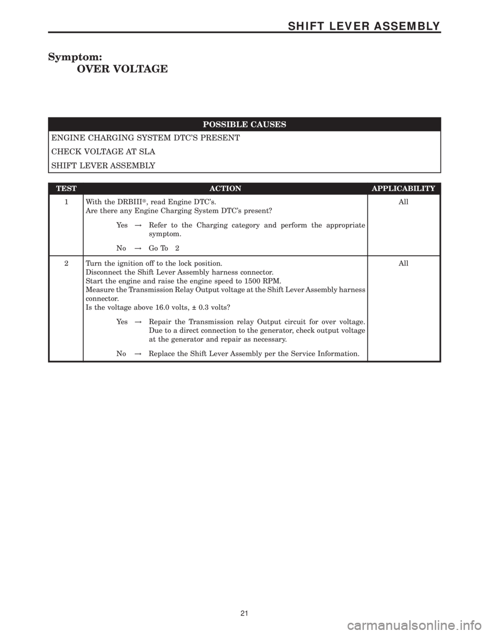
Symptom:
OVER VOLTAGE
POSSIBLE CAUSES
ENGINE CHARGING SYSTEM DTC'S PRESENT
CHECK VOLTAGE AT SLA
SHIFT LEVER ASSEMBLY
TEST ACTION APPLICABILITY
1 With the DRBIIIt, read Engine DTC's.
Are there any Engine Charging System DTC's present?All
Ye s!Refer to the Charging category and perform the appropriate
symptom.
No!Go To 2
2 Turn the ignition off to the lock position.
Disconnect the Shift Lever Assembly harness connector.
Start the engine and raise the engine speed to 1500 RPM.
Measure the Transmission Relay Output voltage at the Shift Lever Assembly harness
connector.
Is the voltage above 16.0 volts, 0.3 volts?All
Ye s!Repair the Transmission relay Output circuit for over voltage.
Due to a direct connection to the generator, check output voltage
at the generator and repair as necessary.
No!Replace the Shift Lever Assembly per the Service Information.
21
SHIFT LEVER ASSEMBLY
Page 2190 of 2305
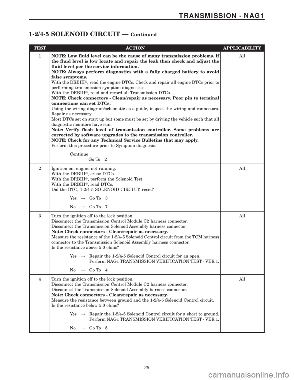
TEST ACTION APPLICABILITY
1NOTE: Low fluid level can be the cause of many transmission problems. If
the fluid level is low locate and repair the leak then check and adjust the
fluid level per the service information.
NOTE: Always perform diagnostics with a fully charged battery to avoid
false symptoms.
With the DRBIIIt, read the engine DTCs. Check and repair all engine DTCs prior to
performing transmission symptom diagnostics.
With the DRBIIIt, read and record all Transmission DTCs.
NOTE: Check connectors - Clean/repair as necessary. Poor pin to terminal
connections can set DTCs.
Using the wiring diagram/schematic as a guide, inspect the wiring and connectors.
Repair as necessary.
Most DTCs set on start up but some must be set by driving the vehicle such that all
diagnostic monitors have run.
Note: Verify flash level of transmission controller. Some problems are
corrected by software upgrades to the transmission controller.
NOTE: Check for any Technical Service Bulletins that may apply.
Perform this procedure prior to Symptom diagnosis.All
Continue
Go To 2
2 Ignition on, engine not running.
With the DRBIIIt, erase DTCs.
With the DRBIIIt, perform the Solenoid Test.
With the DRBIIIt, read DTCs.
Did the DTC, 1-2/4-5 SOLENOID CIRCUIT, reset?All
Ye s!Go To 3
No!Go To 7
3 Turn the ignition off to the lock position.
Disconnect the Transmission Control Module C2 harness connector.
Disconnect the Transmission Solenoid Assembly harness connector
Note: Check connectors - Clean/repair as necessary.
Measure the resistance of the 1-2/4-5 Solenoid Control circuit from the TCM harness
connector to the Transmission Solenoid Assembly harness connector.
Is the resistance above 5.0 ohms?All
Ye s!Repair the 1-2/4-5 Solenoid Control circuit for an open.
Perform NAG1 TRANSMISSION VERIFICATION TEST - VER 1.
No!Go To 4
4 Turn the ignition off to the lock position.
Disconnect the Transmission Control Module C2 harness connector.
Disconnect the Transmission Solenoid Assembly harness connector.
Note: Check connectors - Clean/repair as necessary.
Measure the resistance between ground and the 1-2/4-5 Solenoid Control circuit.
Is the resistance below 5.0 ohms?All
Ye s!Repair the 1-2/4-5 Solenoid Control circuit for a short to ground.
Perform NAG1 TRANSMISSION VERIFICATION TEST - VER 1.
No!Go To 5
25
TRANSMISSION - NAG1
1-2/4-5 SOLENOID CIRCUIT ÐContinued
Page 2193 of 2305

TEST ACTION APPLICABILITY
1NOTE: Low fluid level can be the cause of many transmission problems. If
the fluid level is low locate and repair the leak then check and adjust the
fluid level per the service information.
NOTE: Always perform diagnostics with a fully charged battery to avoid
false symptoms.
With the DRBIIIt, read the engine DTCs. Check and repair all engine DTCs prior to
performing transmission symptom diagnostics.
With the DRBIIIt, read and record all Transmission DTCs.
NOTE: Check connectors - Clean/repair as necessary. Poor pin to terminal
connections can set DTCs.
Using the wiring diagram/schematic as a guide, inspect the wiring and connectors.
Repair as necessary.
Most DTCs set on start up but some must be set by driving the vehicle such that all
diagnostic monitors have run.
Note: Verify flash level of transmission controller. Some problems are
corrected by software upgrades to the transmission controller.
NOTE: Check for any Technical Service Bulletins that may apply.
Perform this procedure prior to Symptom diagnosis.All
Continue
Go To 2
2 Ignition on, engine not running.
With the DRBIIIt, erase DTCs.
With the DRBIIIt, perform the Solenoid Test.
With the DRBIIIt, read DTCs.
Did the DTC, 2-3 SOLENOID CIRCUIT, reset?All
Ye s!Go To 3
No!Go To 7
3 Turn the ignition off to the lock position.
Disconnect the Transmission Control Module C2 harness connector.
Disconnect the Transmission Solenoid Assembly harness connector
Note: Check connectors - Clean/repair as necessary.
Measure the resistance of the 2-3 Solenoid Control circuit from the TCM C2 harness
connector to the Transmission Solenoid Assembly harness connector.
Is the resistance above 5.0 ohms?All
Ye s!Repair the 2-3 Solenoid Control circuit for an open.
Perform NAG1 TRANSMISSION VERIFICATION TEST - VER 1.
No!Go To 4
4 Turn the ignition off to the lock position.
Disconnect the Transmission Control Module C2 harness connector.
Disconnect the Transmission Solenoid Assembly harness connector.
Note: Check connectors - Clean/repair as necessary.
Measure the resistance between ground and the 2-3 Solenoid Control circuit.
Is the resistance below 5.0 ohms?All
Ye s!Repair the 2-3 Solenoid Control circuit for a short to ground.
Perform NAG1 TRANSMISSION VERIFICATION TEST - VER 1.
No!Go To 5
28
TRANSMISSION - NAG1
2-3 SOLENOID CIRCUIT ÐContinued
Page 2196 of 2305
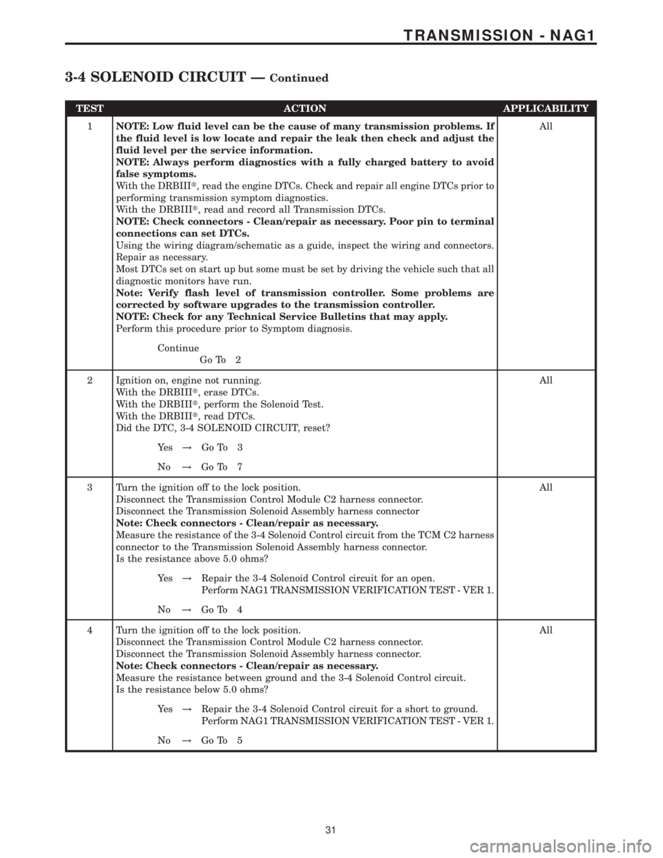
TEST ACTION APPLICABILITY
1NOTE: Low fluid level can be the cause of many transmission problems. If
the fluid level is low locate and repair the leak then check and adjust the
fluid level per the service information.
NOTE: Always perform diagnostics with a fully charged battery to avoid
false symptoms.
With the DRBIIIt, read the engine DTCs. Check and repair all engine DTCs prior to
performing transmission symptom diagnostics.
With the DRBIIIt, read and record all Transmission DTCs.
NOTE: Check connectors - Clean/repair as necessary. Poor pin to terminal
connections can set DTCs.
Using the wiring diagram/schematic as a guide, inspect the wiring and connectors.
Repair as necessary.
Most DTCs set on start up but some must be set by driving the vehicle such that all
diagnostic monitors have run.
Note: Verify flash level of transmission controller. Some problems are
corrected by software upgrades to the transmission controller.
NOTE: Check for any Technical Service Bulletins that may apply.
Perform this procedure prior to Symptom diagnosis.All
Continue
Go To 2
2 Ignition on, engine not running.
With the DRBIIIt, erase DTCs.
With the DRBIIIt, perform the Solenoid Test.
With the DRBIIIt, read DTCs.
Did the DTC, 3-4 SOLENOID CIRCUIT, reset?All
Ye s!Go To 3
No!Go To 7
3 Turn the ignition off to the lock position.
Disconnect the Transmission Control Module C2 harness connector.
Disconnect the Transmission Solenoid Assembly harness connector
Note: Check connectors - Clean/repair as necessary.
Measure the resistance of the 3-4 Solenoid Control circuit from the TCM C2 harness
connector to the Transmission Solenoid Assembly harness connector.
Is the resistance above 5.0 ohms?All
Ye s!Repair the 3-4 Solenoid Control circuit for an open.
Perform NAG1 TRANSMISSION VERIFICATION TEST - VER 1.
No!Go To 4
4 Turn the ignition off to the lock position.
Disconnect the Transmission Control Module C2 harness connector.
Disconnect the Transmission Solenoid Assembly harness connector.
Note: Check connectors - Clean/repair as necessary.
Measure the resistance between ground and the 3-4 Solenoid Control circuit.
Is the resistance below 5.0 ohms?All
Ye s!Repair the 3-4 Solenoid Control circuit for a short to ground.
Perform NAG1 TRANSMISSION VERIFICATION TEST - VER 1.
No!Go To 5
31
TRANSMISSION - NAG1
3-4 SOLENOID CIRCUIT ÐContinued
Page 2198 of 2305
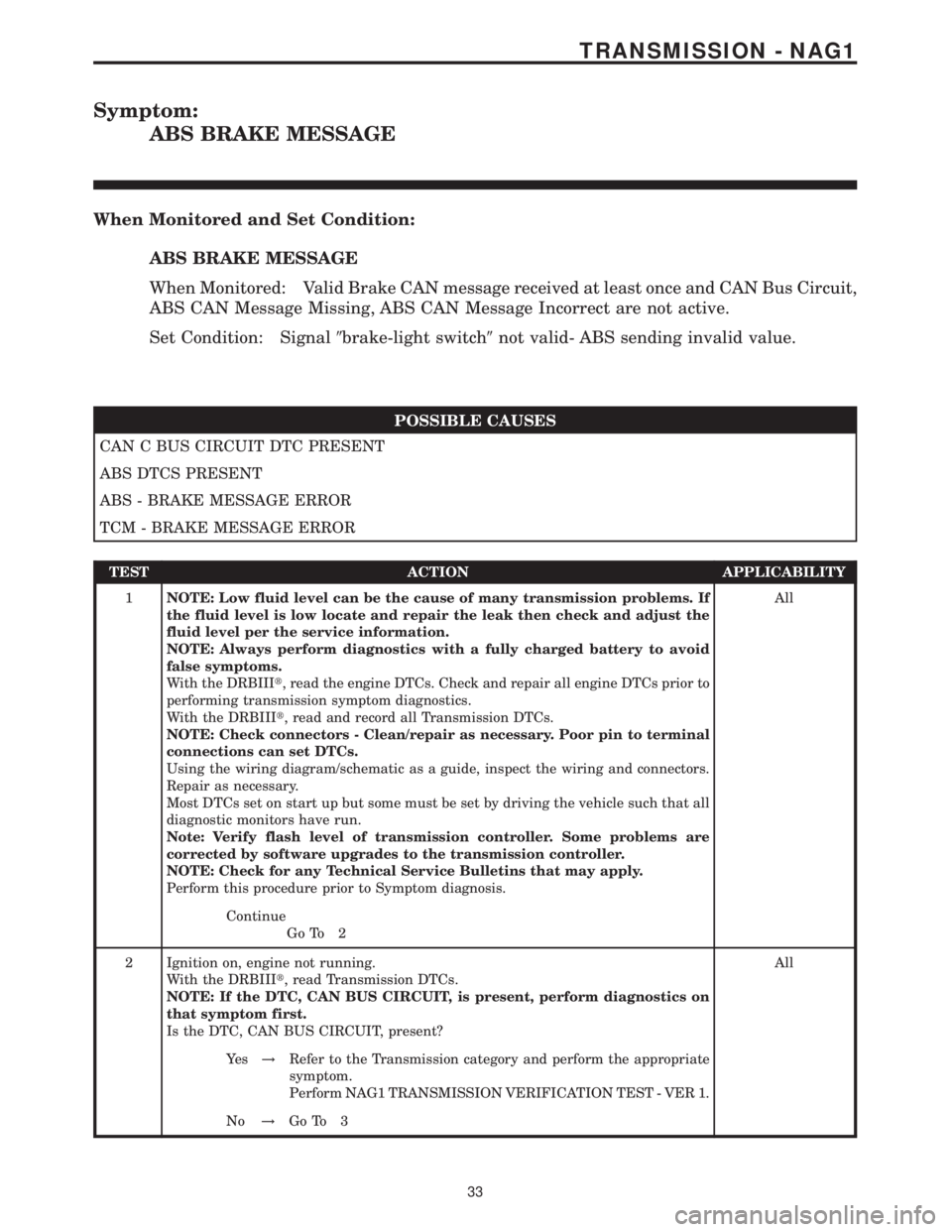
Symptom:
ABS BRAKE MESSAGE
When Monitored and Set Condition:
ABS BRAKE MESSAGE
When Monitored: Valid Brake CAN message received at least once and CAN Bus Circuit,
ABS CAN Message Missing, ABS CAN Message Incorrect are not active.
Set Condition: Signal9brake-light switch9not valid- ABS sending invalid value.
POSSIBLE CAUSES
CAN C BUS CIRCUIT DTC PRESENT
ABS DTCS PRESENT
ABS - BRAKE MESSAGE ERROR
TCM - BRAKE MESSAGE ERROR
TEST ACTION APPLICABILITY
1NOTE: Low fluid level can be the cause of many transmission problems. If
the fluid level is low locate and repair the leak then check and adjust the
fluid level per the service information.
NOTE: Always perform diagnostics with a fully charged battery to avoid
false symptoms.
With the DRBIIIt, read the engine DTCs. Check and repair all engine DTCs prior to
performing transmission symptom diagnostics.
With the DRBIIIt, read and record all Transmission DTCs.
NOTE: Check connectors - Clean/repair as necessary. Poor pin to terminal
connections can set DTCs.
Using the wiring diagram/schematic as a guide, inspect the wiring and connectors.
Repair as necessary.
Most DTCs set on start up but some must be set by driving the vehicle such that all
diagnostic monitors have run.
Note: Verify flash level of transmission controller. Some problems are
corrected by software upgrades to the transmission controller.
NOTE: Check for any Technical Service Bulletins that may apply.
Perform this procedure prior to Symptom diagnosis.All
Continue
Go To 2
2 Ignition on, engine not running.
With the DRBIIIt, read Transmission DTCs.
NOTE: If the DTC, CAN BUS CIRCUIT, is present, perform diagnostics on
that symptom first.
Is the DTC, CAN BUS CIRCUIT, present?All
Ye s!Refer to the Transmission category and perform the appropriate
symptom.
Perform NAG1 TRANSMISSION VERIFICATION TEST - VER 1.
No!Go To 3
33
TRANSMISSION - NAG1
Page 2200 of 2305
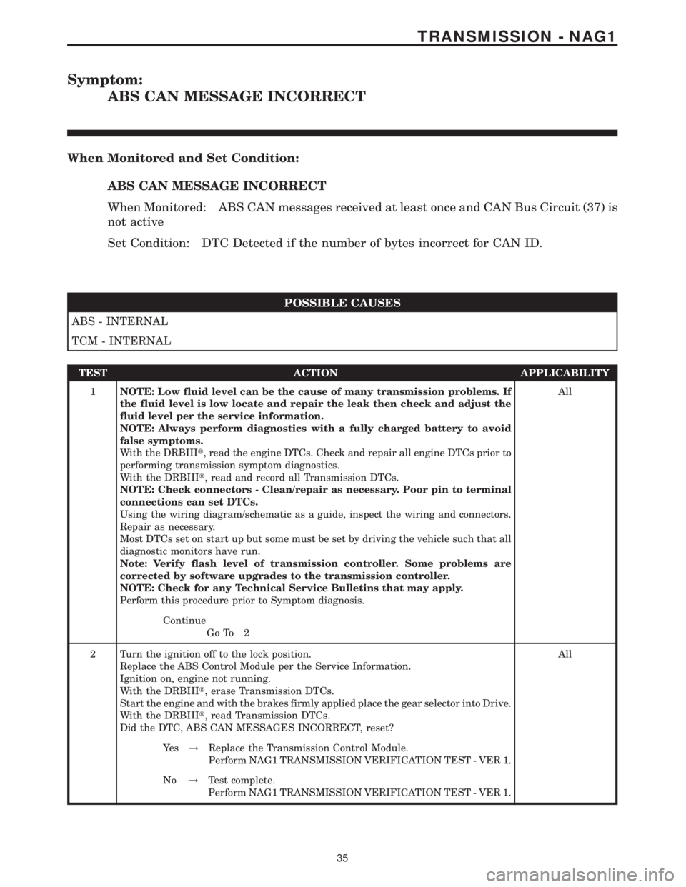
Symptom:
ABS CAN MESSAGE INCORRECT
When Monitored and Set Condition:
ABS CAN MESSAGE INCORRECT
When Monitored: ABS CAN messages received at least once and CAN Bus Circuit (37) is
not active
Set Condition: DTC Detected if the number of bytes incorrect for CAN ID.
POSSIBLE CAUSES
ABS - INTERNAL
TCM - INTERNAL
TEST ACTION APPLICABILITY
1NOTE: Low fluid level can be the cause of many transmission problems. If
the fluid level is low locate and repair the leak then check and adjust the
fluid level per the service information.
NOTE: Always perform diagnostics with a fully charged battery to avoid
false symptoms.
With the DRBIIIt, read the engine DTCs. Check and repair all engine DTCs prior to
performing transmission symptom diagnostics.
With the DRBIIIt, read and record all Transmission DTCs.
NOTE: Check connectors - Clean/repair as necessary. Poor pin to terminal
connections can set DTCs.
Using the wiring diagram/schematic as a guide, inspect the wiring and connectors.
Repair as necessary.
Most DTCs set on start up but some must be set by driving the vehicle such that all
diagnostic monitors have run.
Note: Verify flash level of transmission controller. Some problems are
corrected by software upgrades to the transmission controller.
NOTE: Check for any Technical Service Bulletins that may apply.
Perform this procedure prior to Symptom diagnosis.All
Continue
Go To 2
2 Turn the ignition off to the lock position.
Replace the ABS Control Module per the Service Information.
Ignition on, engine not running.
With the DRBIIIt, erase Transmission DTCs.
Start the engine and with the brakes firmly applied place the gear selector into Drive.
With the DRBIIIt, read Transmission DTCs.
Did the DTC, ABS CAN MESSAGES INCORRECT, reset?All
Ye s!Replace the Transmission Control Module.
Perform NAG1 TRANSMISSION VERIFICATION TEST - VER 1.
No!Test complete.
Perform NAG1 TRANSMISSION VERIFICATION TEST - VER 1.
35
TRANSMISSION - NAG1