2006 MERCEDES-BENZ SPRINTER display
[x] Cancel search: displayPage 1911 of 2305
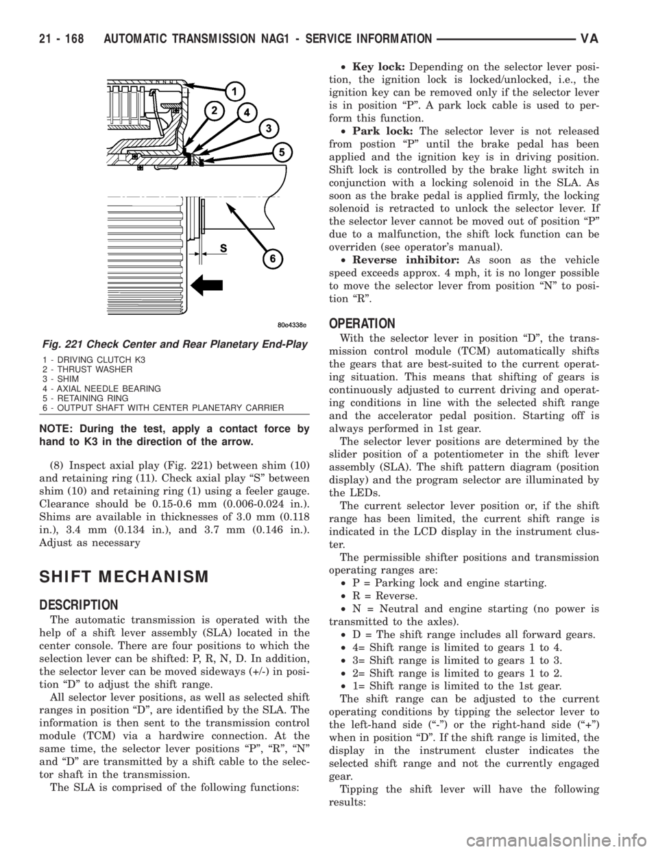
NOTE: During the test, apply a contact force by
hand to K3 in the direction of the arrow.
(8) Inspect axial play (Fig. 221) between shim (10)
and retaining ring (11). Check axial play ªSº between
shim (10) and retaining ring (1) using a feeler gauge.
Clearance should be 0.15-0.6 mm (0.006-0.024 in.).
Shims are available in thicknesses of 3.0 mm (0.118
in.), 3.4 mm (0.134 in.), and 3.7 mm (0.146 in.).
Adjust as necessary
SHIFT MECHANISM
DESCRIPTION
The automatic transmission is operated with the
help of a shift lever assembly (SLA) located in the
center console. There are four positions to which the
selection lever can be shifted: P, R, N, D. In addition,
the selector lever can be moved sideways (+/-) in posi-
tion ªDº to adjust the shift range.
All selector lever positions, as well as selected shift
ranges in position ªDº, are identified by the SLA. The
information is then sent to the transmission control
module (TCM) via a hardwire connection. At the
same time, the selector lever positions ªPº, ªRº, ªNº
and ªDº are transmitted by a shift cable to the selec-
tor shaft in the transmission.
The SLA is comprised of the following functions:²Key lock:Depending on the selector lever posi-
tion, the ignition lock is locked/unlocked, i.e., the
ignition key can be removed only if the selector lever
is in position ªPº. A park lock cable is used to per-
form this function.
²Park lock:The selector lever is not released
from postion ªPº until the brake pedal has been
applied and the ignition key is in driving position.
Shift lock is controlled by the brake light switch in
conjunction with a locking solenoid in the SLA. As
soon as the brake pedal is applied firmly, the locking
solenoid is retracted to unlock the selector lever. If
the selector lever cannot be moved out of position ªPº
due to a malfunction, the shift lock function can be
overriden (see operator's manual).
²Reverse inhibitor:As soon as the vehicle
speed exceeds approx. 4 mph, it is no longer possible
to move the selector lever from position ªNº to posi-
tion ªRº.
OPERATION
With the selector lever in position ªDº, the trans-
mission control module (TCM) automatically shifts
the gears that are best-suited to the current operat-
ing situation. This means that shifting of gears is
continuously adjusted to current driving and operat-
ing conditions in line with the selected shift range
and the accelerator pedal position. Starting off is
always performed in 1st gear.
The selector lever positions are determined by the
slider position of a potentiometer in the shift lever
assembly (SLA). The shift pattern diagram (position
display) and the program selector are illuminated by
the LEDs.
The current selector lever position or, if the shift
range has been limited, the current shift range is
indicated in the LCD display in the instrument clus-
ter.
The permissible shifter positions and transmission
operating ranges are:
²P = Parking lock and engine starting.
²R = Reverse.
²N = Neutral and engine starting (no power is
transmitted to the axles).
²D = The shift range includes all forward gears.
²4= Shift range is limited to gears 1 to 4.
²3= Shift range is limited to gears 1 to 3.
²2= Shift range is limited to gears 1 to 2.
²1= Shift range is limited to the 1st gear.
The shift range can be adjusted to the current
operating conditions by tipping the selector lever to
the left-hand side (ª-º) or the right-hand side (ª+º)
when in position ªDº. If the shift range is limited, the
display in the instrument cluster indicates the
selected shift range and not the currently engaged
gear.
Tipping the shift lever will have the following
results:Fig. 221 Check Center and Rear Planetary End-Play
1 - DRIVING CLUTCH K3
2 - THRUST WASHER
3 - SHIM
4 - AXIAL NEEDLE BEARING
5 - RETAINING RING
6 - OUTPUT SHAFT WITH CENTER PLANETARY CARRIER
21 - 168 AUTOMATIC TRANSMISSION NAG1 - SERVICE INFORMATIONVA
Page 1912 of 2305
²Tipping the selector lever toward ª-º one
time after another:The shift range is reduced in
descending sequence by one gear each time, i.e., from
D-4-3-2-1.Iftheselected limitation of the shift
range would result in a downshift causing excessive
engine speed, the shifting is not executed and the
engaged gear as well as the shift range remain
unchanged. This is to prevent the engine from over-
speeding. Engine retardation is low with the selector
lever in position ªDº. To make use of the full braking
power of the engine, ªmanualº downshifting by tip-
ping the lever towards the left-hand side is recom-
mended. If this has been done, subsequent upshifting
must be carried out manually as well.
²Tipping the selector lever toward ª-º and
holding it in this position:The currently engaged
gear in range ªDº is indicated in the instrument clus-
ter display and the shift range is limited to this gear.
²Tipping the selector lever toward ª+º one
time after another:The shift range is increased by
one gear each time and the increased shift range is
displayed in the instrument cluster; possibly, the
transmission upshifts to a faster gear.
²Tipping the selector lever toward ª+º sev-
eral times:The shift range is increased by one gear
each time the lever is tipped until the shift range
ends up in ªDº.
²Tipping the selector lever toward ª+º and
holding it in this position:The shift range is
extended immediately to ªDº, shift ranges are indi-
cated in ascending sequence; possibly, the transmis-
sion upshifts to a faster gear due to the extension of
the shift range.
REMOVAL
(1) Move selector lever to position ªDº.
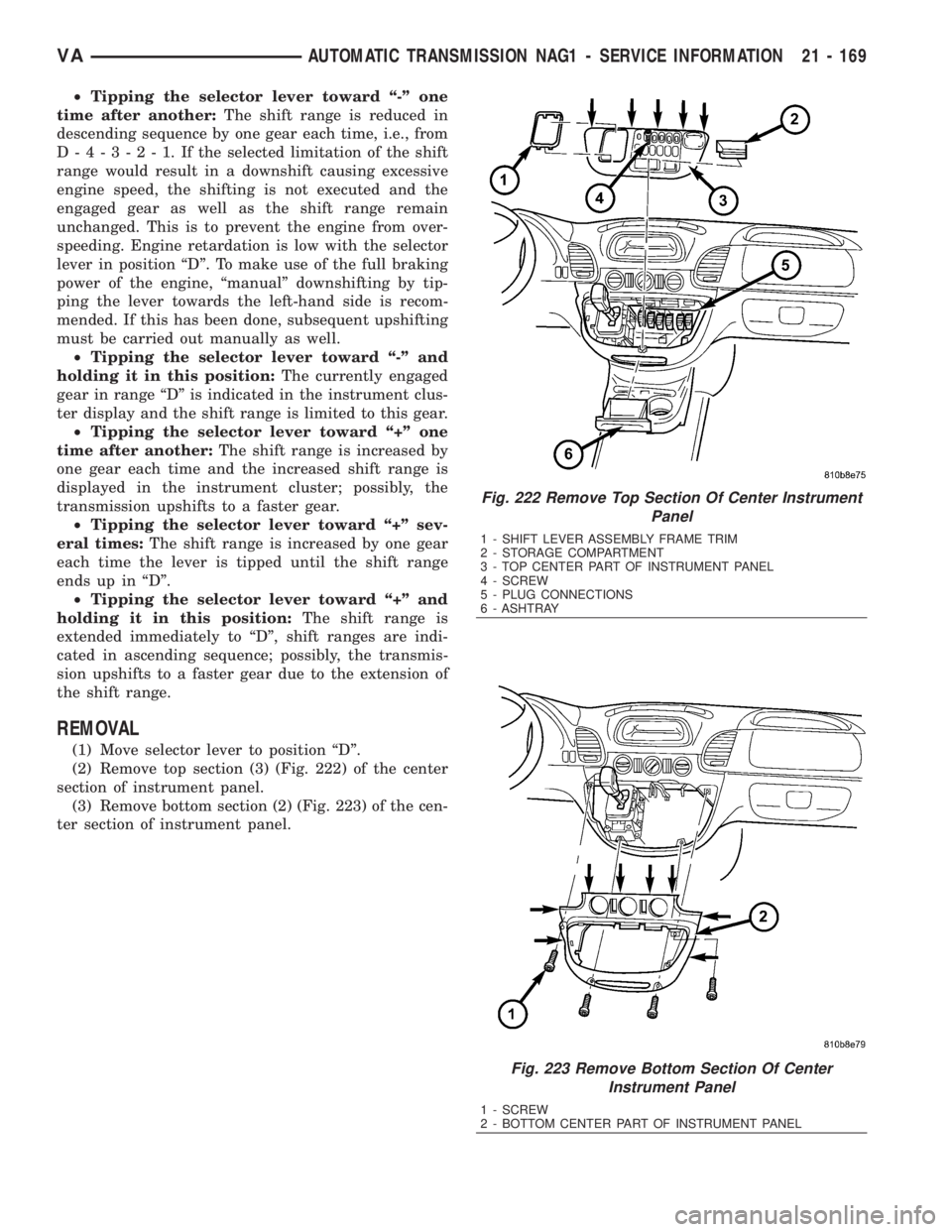
(2) Remove top section (3) (Fig. 222) of the center
section of instrument panel.
(3) Remove bottom section (2) (Fig. 223) of the cen-
ter section of instrument panel.
Fig. 222 Remove Top Section Of Center Instrument
Panel
1 - SHIFT LEVER ASSEMBLY FRAME TRIM
2 - STORAGE COMPARTMENT
3 - TOP CENTER PART OF INSTRUMENT PANEL
4 - SCREW
5 - PLUG CONNECTIONS
6 - ASHTRAY
Fig. 223 Remove Bottom Section Of Center
Instrument Panel
1 - SCREW
2 - BOTTOM CENTER PART OF INSTRUMENT PANEL
VAAUTOMATIC TRANSMISSION NAG1 - SERVICE INFORMATION 21 - 169
Page 2162 of 2305
TABLE OF CONTENTS
1.0 INTRODUCTION.........................................................1
1.1SYSTEM COVERAGE...............................................1
1.2SIX -STEP TROUBLESHOOTING PROCEDURE..........................1
2.0 IDENTIFICATION OF SYSTEM.............................................1
3.0 SYSTEM DESCRIPTION AND FUNCTIONAL OPERATION......................1
3.1GENERAL DESCRIPTION............................................1
3.2FUNCTIONAL OPERATION...........................................1
3.2.1CONTROLLER MODES OF OPERATION........................2
3.2.2MIL ILLUMINATION..........................................2
3.2.3SOLENOIDS...............................................2
3.2.4TRANSMISSION COMPONENT DESCRIPTIONS.................3
3.2.5TRANSMISSION OPERATION AND SHIFT SCHEDULING..........4
3.2.6TRANSMISSION ADAPTIVES - INITIALIZE AND STORE...........4
3.3DIAGNOSTIC TROUBLE CODES......................................4
3.3.1ACTIVE (HARD) CODE......................................4
3.3.2STORED (INTERMITTENT) CODE.............................4
3.3.3TROUBLE CODE ERASURE..................................5
3.4USING THE DRBIIIT.................................................5
3.5DRBIIITERROR MESSAGES.........................................5
3.5.1DRBIIITDOES NOT POWER UP (BLANK SCREEN)...............5
3.5.2DISPLAY IS NOT VISIBLE....................................5
4.0 DISCLAIMERS, SAFETY, AND WARNINGS..................................5
4.1DISCLAIMERS......................................................5
4.2SAFETY...........................................................6
4.2.1TECHNICIAN SAFETY INFORMATION..........................6
4.2.2VEHICLE PREPARATION FOR TESTING........................6
4.2.3SERVICING SUB-ASSEMBLIES...............................6
4.2.4DRBIIITSAFETY INFORMATION...............................6
4.3WARNINGS........................................................7
4.3.1VEHICLE DAMAGE WARNINGS...............................7
4.3.2ROAD TESTING A COMPLAINT VEHICLE.......................7
4.4.4BULLETINS AND RECALLS...................................7
5.0 REQUIRED TOOLS AND EQUIPMENT......................................8
6.0 GLOSSARY OF TERMS...................................................8
6.1ACRONYMS.......................................................8
6.2DEFINITIONS......................................................8
7.0 DIAGNOSTIC INFORMATION AND PROCEDURES............................9
COMMUNICATION
*NO RESPONSE FROM SHIFTER ASSEMBLY...............................10
*NO RESPONSE FROM TRANSMISSION CONTROL MODULE.................12
SHIFT LEVER ASSEMBLY
BACKUP LAMP CKT SHORT TO GROUND..................................14
i
Page 2169 of 2305
3.2.5 TRANSMISSION OPERATION AND
SHIFT SCHEDULING
The transmission covered in this manual has
unique shift schedules depending on the tempera-
ture of the transmission oil. The transmission oil
temperature has a decisive effect on the shift qual-
ity of the transmission. The shift schedule is modi-
fied to extend the life of the transmission while
operating under extreme conditions and to improve
driver comfort by modifying shift schedules.
The transmission oil temperature is measured
with a Temperature Sensor on the NAG1 transmis-
sion. The Temperature Sensor is an integral com-
ponent of the Transmission Solenoid assembly. If
the Temperature Sensor is causing a problem, a
DTC will be set in the TCM.
The Transmission Temperature Sensor is wired in
series with the Park /Neutral (P/N) switch. The P/N
switch is also located in the transmission. The trans-
mission temperature is only read by the TCM when
the P/N switch closes while in the R, D position.
When the shifter lever is in the park or neutral
position, the P/N switch opens and the temperature
being displayed is Engine temperature.
AutoStick Feature (If equipped)
This feature allows the driver to manually shift the
transaxle when the shift lever is moved sideways to
the (+ / -) in position D to adjust the shift range.
3.2.6 TRANSMISSION ADAPTIVES -
INITIALIZE AND STORE
Initialize Adaptive -This TCM function should be
used when a new transmission has been placed in
the vehicle. This command will reset the TCM
adaptive to the factory setting.
Store Adaptive -This command should be used
after the vehicle has been test driven by the tech-
nician to store any learned adaptive changes that
occurred during the test drive. During normal op-
eration adaptive are updated every 10 minutes.
Using this command the latest adaptive will be
written to the TCM immediately.
3.3 DIAGNOSTIC TROUBLE CODES
Diagnostic trouble codes (DTC's) are codes stored
by the Transmission Control Module (TCM) and the
Shift Lever Assembly Module (SLA) to help diag-
nose Transmission and Shifter problems. They are
viewed using the DRBIIItscan tool.
Always begin by performing a visual inspection of
the wiring, connectors, cooler lines and the trans-
mission. Any obvious wiring problems or leaks
should be repaired prior to performing any diagnos-
tic test procedures. Some engine driveability prob-lems can be misinterpreted as a transmission prob-
lem. Ensure that the engine is running properly
and that no ECM DTC's are present that could
cause a transmission complaint.
If there is a communication K-ABS,Shifter or
K-TCM circuit problem, trouble codes will not be
accessible until the problem is fixed. The DRBIIIt
will display an appropriate message. The following
is a possible list of causes for a bus problem:
± open or short to ground/battery in K line
circuit.
± internal failure of any module or component
connected to the K line circuit
Each diagnostic trouble code is diagnosed by
following a specific testing sequence. The diagnostic
test procedures contain step-by-step instructions
for determining the cause of a transmission diag-
nostic trouble code. Possible sources of the code are
checked and eliminated one by one. It is not neces-
sary to perform all of the tests in this book to
diagnose an individual code. These tests are based
on the problem being present at the time that the
test is run.
If the TCM records a DTC that will adversely
affect the vehicles transmission, it will request (via
the communication bus) that the ECM illuminate
the Malfunction Indicator Lamp (MIL). All trans-
mission DTC's will be stored in the TCM.
3.3.1 ACTIVE (HARD) CODE
Any Diagnostic Trouble Code (DTC) that is set
whenever the system or component is monitored is
an Active code. This means that the problem is
there every time the TCM checks that system or
component. Some codes will set immediately at
start up and others will require a road test under
specific conditions to set the DTC. It must be
determined if a code is Active (repeatable) or Stored
(Intermittent) before attempting diagnosis.
3.3.2 STORED (INTERMITTENT) CODE
A diagnostic trouble code that is not there every
time the TCM checks the circuit or function is a
Stored (Intermittent) code. Problems that come and
go like this are the most difficult to diagnose, they
must be looked for under the specific conditions
that cause them. If the DTC is reset (after an
ignition cycle) the DTC will be set to Stored (Inter-
mittent) status. A DTC status can be9Active9or
9Stored9(Intermittent). Active is when the DTC is
present in the controller and the transmission is in
the particular mode of operation for that DTC.
Stored means that the DTC occurred at some point,
but is not currently present, or the conditions have
not been right to check for the presence of the
problem, when a DTC is classified as Stored (Inter-
mittent), no TCM reaction is required.
4
GENERAL INFORMATION
Page 2170 of 2305
Emergency running function
If DTCs occur, safe-driving conditions must be re-
tained but full functionality of the transmission will
be limited to avoid damaging the automatic trans-
mission. In the event of certain DTCs the TCM
switches to emergency running. The TCM will store
the appropriate DTC codes and solenoids will be
de-energized (turned off)
The transmission effects will be:
²The last gear shifted remains in that position
²The modulating pressure and shift pressure in-
crease to maximum value
²The torque converter clutch is disengaged
(turned off)
Shifting manually after a DTC detection
NOTE: The vehicle can still be shifted
manually to 2nd or reverse gear.
To accomplish these shifts you must
Stop the vehicle
Turn the ignition off
Start the engine
Place the selector lever into D for 2nd gear
Place the selector lever into R for reverse gear
The emergency running function is retained until
the DTC is eliminated or the stored DTC code is
erased.
Stored (Intermittent) DTCs can be reset by cy-
cling the ignition switch
3.3.3 TROUBLE CODE ERASURE
Diagnostic Trouble Codes can be erased in two
ways. The first is to erase the DTC with the DRBIII
or scan tool. The second is if the DTC is no longer
present, the DTC is reset by the TCM (after an
ignition cycle), which will place the DTC in an
intermittent status (Stored DTC).
When there are no diagnostic trouble codes
stored in memory, the DRBIIItwill display
(NO DTC's DETECTED(
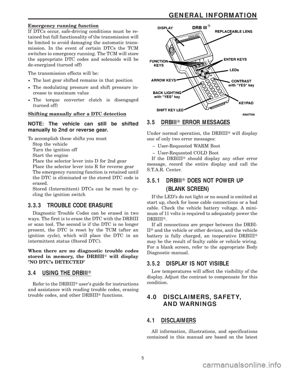
3.4 USING THE DRBIIIT
Refer to the DRBIIItuser's guide for instructions
and assistance with reading trouble codes, erasing
trouble codes, and other DRBIIItfunctions.
3.5 DRBIIITERROR MESSAGES
Under normal operation, the DRBIIItwill display
one of only two error messages:
± User-Requested WARM Boot
± User-Requested COLD Boot
If the DRBIIItshould display any other error
message, record the entire display and call the
S.T.A.R. Center.
3.5.1 DRBIIITDOES NOT POWER UP
(BLANK SCREEN)
If the LED's do not light or no sound is emitted at
start up, check for loose cable connections or a bad
cable. Check the vehicle battery voltage. A mini-
mum of 11 volts is required to adequately power the
DRBIIIt.
If all connections are proper between the DRBI-
IItand the vehicle or other devices, and the vehicle
battery is fully charged, an inoperative DRBIIIt
may be the result of faulty cable or vehicle wiring.
For a blank screen, refer to the appropriate Body
Diagnostic manual.
3.5.2 DISPLAY IS NOT VISIBLE
Low temperatures will affect the visibility of the
display. Adjust the contrast to compensate for this
condition.
4.0 DISCLAIMERS, SAFETY,
AND WARNINGS
4.1 DISCLAIMERS
All information, illustrations, and specifications
contained in this manual are based on the latest
5
GENERAL INFORMATION
Page 2212 of 2305
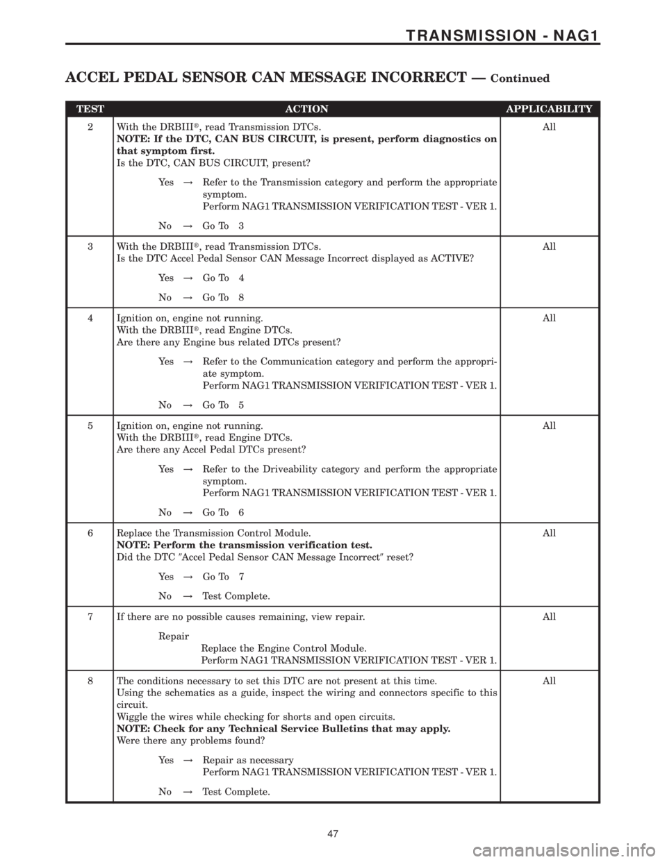
TEST ACTION APPLICABILITY
2 With the DRBIIIt, read Transmission DTCs.
NOTE: If the DTC, CAN BUS CIRCUIT, is present, perform diagnostics on
that symptom first.
Is the DTC, CAN BUS CIRCUIT, present?All
Ye s!Refer to the Transmission category and perform the appropriate
symptom.
Perform NAG1 TRANSMISSION VERIFICATION TEST - VER 1.
No!Go To 3
3 With the DRBIIIt, read Transmission DTCs.
Is the DTC Accel Pedal Sensor CAN Message Incorrect displayed as ACTIVE?All
Ye s!Go To 4
No!Go To 8
4 Ignition on, engine not running.
With the DRBIIIt, read Engine DTCs.
Are there any Engine bus related DTCs present?All
Ye s!Refer to the Communication category and perform the appropri-
ate symptom.
Perform NAG1 TRANSMISSION VERIFICATION TEST - VER 1.
No!Go To 5
5 Ignition on, engine not running.
With the DRBIIIt, read Engine DTCs.
Are there any Accel Pedal DTCs present?All
Ye s!Refer to the Driveability category and perform the appropriate
symptom.
Perform NAG1 TRANSMISSION VERIFICATION TEST - VER 1.
No!Go To 6
6 Replace the Transmission Control Module.
NOTE: Perform the transmission verification test.
Did the DTC9Accel Pedal Sensor CAN Message Incorrect9reset?All
Ye s!Go To 7
No!Test Complete.
7 If there are no possible causes remaining, view repair. All
Repair
Replace the Engine Control Module.
Perform NAG1 TRANSMISSION VERIFICATION TEST - VER 1.
8 The conditions necessary to set this DTC are not present at this time.
Using the schematics as a guide, inspect the wiring and connectors specific to this
circuit.
Wiggle the wires while checking for shorts and open circuits.
NOTE: Check for any Technical Service Bulletins that may apply.
Were there any problems found?All
Ye s!Repair as necessary
Perform NAG1 TRANSMISSION VERIFICATION TEST - VER 1.
No!Test Complete.
47
TRANSMISSION - NAG1
ACCEL PEDAL SENSOR CAN MESSAGE INCORRECT ÐContinued
Page 2244 of 2305
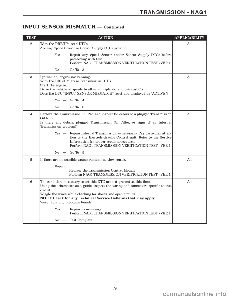
TEST ACTION APPLICABILITY
2 With the DRBIIIt, read DTCs.
Are any Speed Sensor or Sensor Supply DTCs present?All
Ye s!Repair any Speed Sensor and/or Sensor Supply DTCs before
proceeding with test.
Perform NAG1 TRANSMISSION VERIFICATION TEST - VER 1.
No!Go To 3
3 Ignition on, engine not running.
With the DRBIIIt, erase Transmission DTCs.
Start the engine.
Drive the vehicle to speeds to allow multiple 2-3 and 3-4 upshifts.
Does the DTC9INPUT SENSOR MISMATCH9reset and displayed as9ACTIVE9?All
Ye s!Go To 4
No!Go To 6
4 Remove the Transmission Oil Pan and inspect for debris or a plugged Transmission
Oil Filter.
Is there any debris, plugged Transmission Oil Filter, or signs of an Internal
Transmission problem?All
Ye s!Repair Internal Transmission as necessary. Pay particular atten-
tion to the Electrohydraulic Control unit. Refer to the Service
Information for proper repair procedures.
Perform NAG1 TRANSMISSION VERIFICATION TEST - VER 1.
No!Go To 5
5 If there are no possible causes remaining, view repair. All
Repair
Replace the Transmission Control Module.
Perform NAG1 TRANSMISSION VERIFICATION TEST - VER 1.
6 The conditions necessary to set this DTC are not present at this time.
Using the schematics as a guide, inspect the wiring and connectors specific to this
circuit.
Wiggle the wires while checking for shorts and open circuits.
NOTE: Check for any Technical Service Bulletins that may apply.
Were there any problems found?All
Ye s!Repair as necessary
Perform NAG1 TRANSMISSION VERIFICATION TEST - VER 1.
No!Test Complete.
79
TRANSMISSION - NAG1
INPUT SENSOR MISMATCH ÐContinued
Page 2246 of 2305
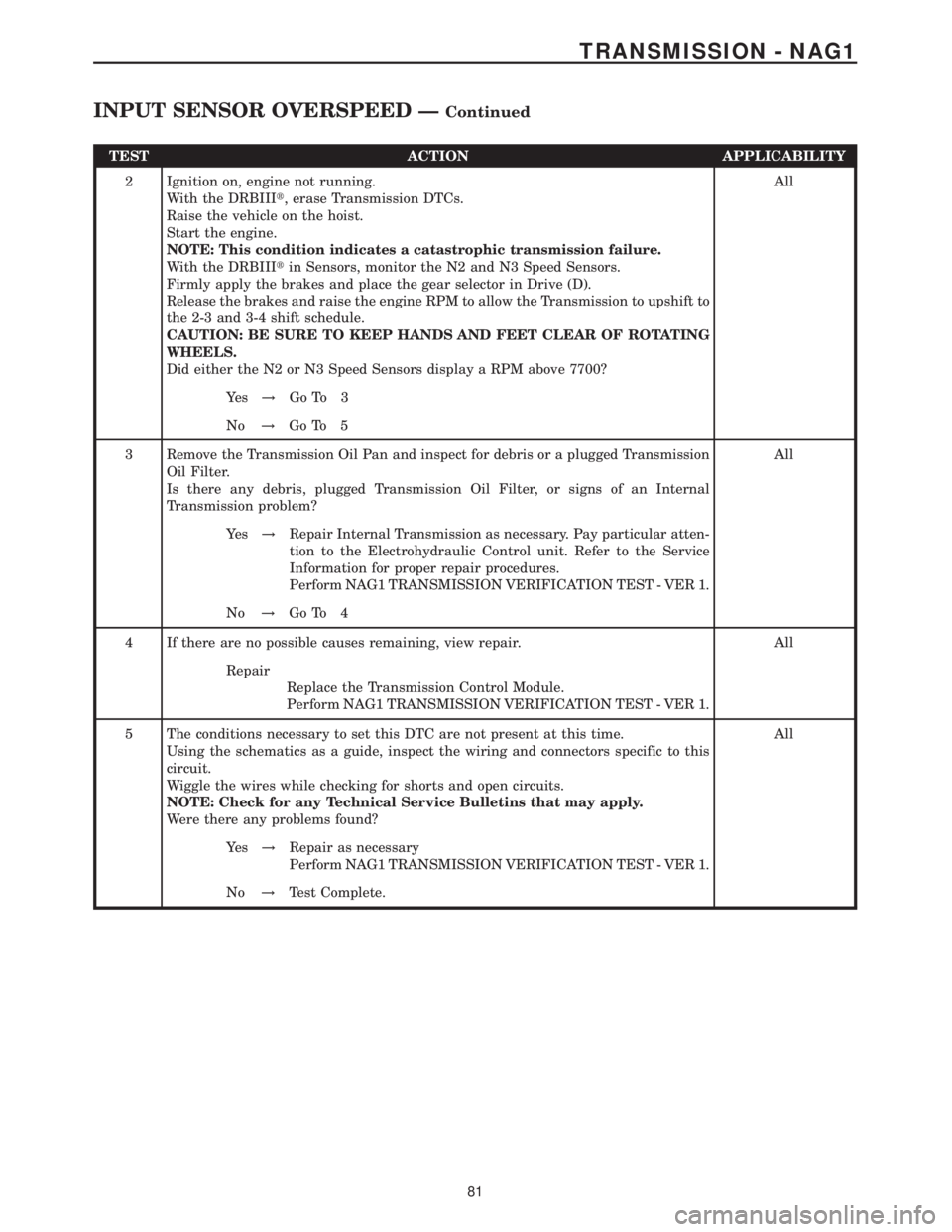
TEST ACTION APPLICABILITY
2 Ignition on, engine not running.
With the DRBIIIt, erase Transmission DTCs.
Raise the vehicle on the hoist.
Start the engine.
NOTE: This condition indicates a catastrophic transmission failure.
With the DRBIIItin Sensors, monitor the N2 and N3 Speed Sensors.
Firmly apply the brakes and place the gear selector in Drive (D).
Release the brakes and raise the engine RPM to allow the Transmission to upshift to
the 2-3 and 3-4 shift schedule.
CAUTION: BE SURE TO KEEP HANDS AND FEET CLEAR OF ROTATING
WHEELS.
Did either the N2 or N3 Speed Sensors display a RPM above 7700?All
Ye s!Go To 3
No!Go To 5
3 Remove the Transmission Oil Pan and inspect for debris or a plugged Transmission
Oil Filter.
Is there any debris, plugged Transmission Oil Filter, or signs of an Internal
Transmission problem?All
Ye s!Repair Internal Transmission as necessary. Pay particular atten-
tion to the Electrohydraulic Control unit. Refer to the Service
Information for proper repair procedures.
Perform NAG1 TRANSMISSION VERIFICATION TEST - VER 1.
No!Go To 4
4 If there are no possible causes remaining, view repair. All
Repair
Replace the Transmission Control Module.
Perform NAG1 TRANSMISSION VERIFICATION TEST - VER 1.
5 The conditions necessary to set this DTC are not present at this time.
Using the schematics as a guide, inspect the wiring and connectors specific to this
circuit.
Wiggle the wires while checking for shorts and open circuits.
NOTE: Check for any Technical Service Bulletins that may apply.
Were there any problems found?All
Ye s!Repair as necessary
Perform NAG1 TRANSMISSION VERIFICATION TEST - VER 1.
No!Test Complete.
81
TRANSMISSION - NAG1
INPUT SENSOR OVERSPEED ÐContinued