2006 MERCEDES-BENZ SPRINTER display
[x] Cancel search: displayPage 2253 of 2305
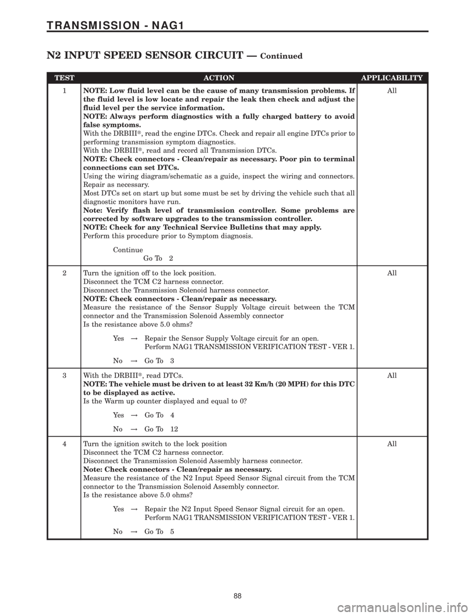
TEST ACTION APPLICABILITY
1NOTE: Low fluid level can be the cause of many transmission problems. If
the fluid level is low locate and repair the leak then check and adjust the
fluid level per the service information.
NOTE: Always perform diagnostics with a fully charged battery to avoid
false symptoms.
With the DRBIIIt, read the engine DTCs. Check and repair all engine DTCs prior to
performing transmission symptom diagnostics.
With the DRBIIIt, read and record all Transmission DTCs.
NOTE: Check connectors - Clean/repair as necessary. Poor pin to terminal
connections can set DTCs.
Using the wiring diagram/schematic as a guide, inspect the wiring and connectors.
Repair as necessary.
Most DTCs set on start up but some must be set by driving the vehicle such that all
diagnostic monitors have run.
Note: Verify flash level of transmission controller. Some problems are
corrected by software upgrades to the transmission controller.
NOTE: Check for any Technical Service Bulletins that may apply.
Perform this procedure prior to Symptom diagnosis.All
Continue
Go To 2
2 Turn the ignition off to the lock position.
Disconnect the TCM C2 harness connector.
Disconnect the Transmission Solenoid harness connector.
NOTE: Check connectors - Clean/repair as necessary.
Measure the resistance of the Sensor Supply Voltage circuit between the TCM
connector and the Transmission Solenoid Assembly connector
Is the resistance above 5.0 ohms?All
Ye s!Repair the Sensor Supply Voltage circuit for an open.
Perform NAG1 TRANSMISSION VERIFICATION TEST - VER 1.
No!Go To 3
3 With the DRBIIIt, read DTCs.
NOTE: The vehicle must be driven to at least 32 Km/h (20 MPH) for this DTC
to be displayed as active.
Is the Warm up counter displayed and equal to 0?All
Ye s!Go To 4
No!Go To 12
4 Turn the ignition switch to the lock position
Disconnect the TCM C2 harness connector.
Disconnect the Transmission Solenoid Assembly harness connector.
Note: Check connectors - Clean/repair as necessary.
Measure the resistance of the N2 Input Speed Sensor Signal circuit from the TCM
connector to the Transmission Solenoid Assembly connector.
Is the resistance above 5.0 ohms?All
Ye s!Repair the N2 Input Speed Sensor Signal circuit for an open.
Perform NAG1 TRANSMISSION VERIFICATION TEST - VER 1.
No!Go To 5
88
TRANSMISSION - NAG1
N2 INPUT SPEED SENSOR CIRCUIT ÐContinued
Page 2257 of 2305
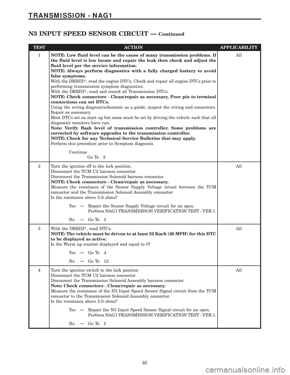
TEST ACTION APPLICABILITY
1NOTE: Low fluid level can be the cause of many transmission problems. If
the fluid level is low locate and repair the leak then check and adjust the
fluid level per the service information.
NOTE: Always perform diagnostics with a fully charged battery to avoid
false symptoms.
With the DRBIIIt, read the engine DTCs. Check and repair all engine DTCs prior to
performing transmission symptom diagnostics.
With the DRBIIIt, read and record all Transmission DTCs.
NOTE: Check connectors - Clean/repair as necessary. Poor pin to terminal
connections can set DTCs.
Using the wiring diagram/schematic as a guide, inspect the wiring and connectors.
Repair as necessary.
Most DTCs set on start up but some must be set by driving the vehicle such that all
diagnostic monitors have run.
Note: Verify flash level of transmission controller. Some problems are
corrected by software upgrades to the transmission controller.
NOTE: Check for any Technical Service Bulletins that may apply.
Perform this procedure prior to Symptom diagnosis.All
Continue
Go To 2
2 Turn the ignition off to the lock position.
Disconnect the TCM C2 harness connector.
Disconnect the Transmission Solenoid harness connector.
NOTE: Check connectors - Clean/repair as necessary.
Measure the resistance of the Sensor Supply Voltage circuit between the TCM
connector and the Transmission Solenoid Assembly connector
Is the resistance above 5.0 ohms?All
Ye s!Repair the Sensor Supply Voltage circuit for an open.
Perform NAG1 TRANSMISSION VERIFICATION TEST - VER 1.
No!Go To 3
3 With the DRBIIIt, read DTCs.
NOTE: The vehicle must be driven to at least 32 Km/h (20 MPH) for this DTC
to be displayed as active.
Is the Warm up counter displayed and equal to 0?All
Ye s!Go To 4
No!Go To 12
4 Turn the ignition switch to the lock position
Disconnect the TCM C2 harness connector.
Disconnect the Transmission Solenoid Assembly harness connector.
Note: Check connectors - Clean/repair as necessary.
Measure the resistance of the N3 Input Speed Sensor Signal circuit from the TCM
connector to the Transmission Solenoid Assembly connector.
Is the resistance above 5.0 ohms?All
Ye s!Repair the N3 Input Speed Sensor Signal circuit for an open.
Perform NAG1 TRANSMISSION VERIFICATION TEST - VER 1.
No!Go To 5
92
TRANSMISSION - NAG1
N3 INPUT SPEED SENSOR CIRCUIT ÐContinued
Page 2260 of 2305
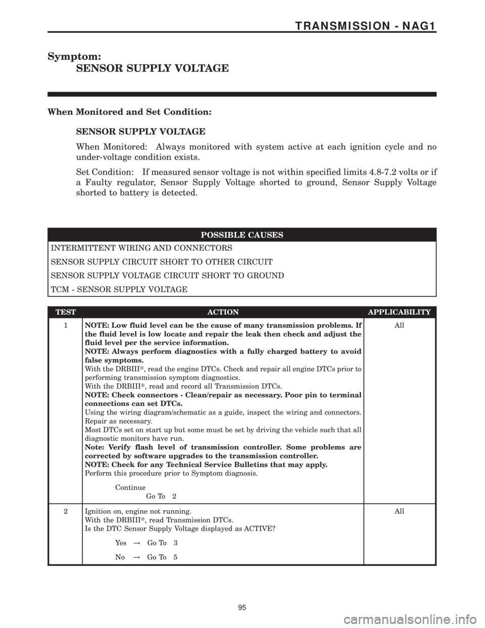
Symptom:
SENSOR SUPPLY VOLTAGE
When Monitored and Set Condition:
SENSOR SUPPLY VOLTAGE
When Monitored: Always monitored with system active at each ignition cycle and no
under-voltage condition exists.
Set Condition: If measured sensor voltage is not within specified limits 4.8-7.2 volts or if
a Faulty regulator, Sensor Supply Voltage shorted to ground, Sensor Supply Voltage
shorted to battery is detected.
POSSIBLE CAUSES
INTERMITTENT WIRING AND CONNECTORS
SENSOR SUPPLY CIRCUIT SHORT TO OTHER CIRCUIT
SENSOR SUPPLY VOLTAGE CIRCUIT SHORT TO GROUND
TCM - SENSOR SUPPLY VOLTAGE
TEST ACTION APPLICABILITY
1NOTE: Low fluid level can be the cause of many transmission problems. If
the fluid level is low locate and repair the leak then check and adjust the
fluid level per the service information.
NOTE: Always perform diagnostics with a fully charged battery to avoid
false symptoms.
With the DRBIIIt, read the engine DTCs. Check and repair all engine DTCs prior to
performing transmission symptom diagnostics.
With the DRBIIIt, read and record all Transmission DTCs.
NOTE: Check connectors - Clean/repair as necessary. Poor pin to terminal
connections can set DTCs.
Using the wiring diagram/schematic as a guide, inspect the wiring and connectors.
Repair as necessary.
Most DTCs set on start up but some must be set by driving the vehicle such that all
diagnostic monitors have run.
Note: Verify flash level of transmission controller. Some problems are
corrected by software upgrades to the transmission controller.
NOTE: Check for any Technical Service Bulletins that may apply.
Perform this procedure prior to Symptom diagnosis.All
Continue
Go To 2
2 Ignition on, engine not running.
With the DRBIIIt, read Transmission DTCs.
Is the DTC Sensor Supply Voltage displayed as ACTIVE?All
Ye s!Go To 3
No!Go To 5
95
TRANSMISSION - NAG1
Page 2268 of 2305
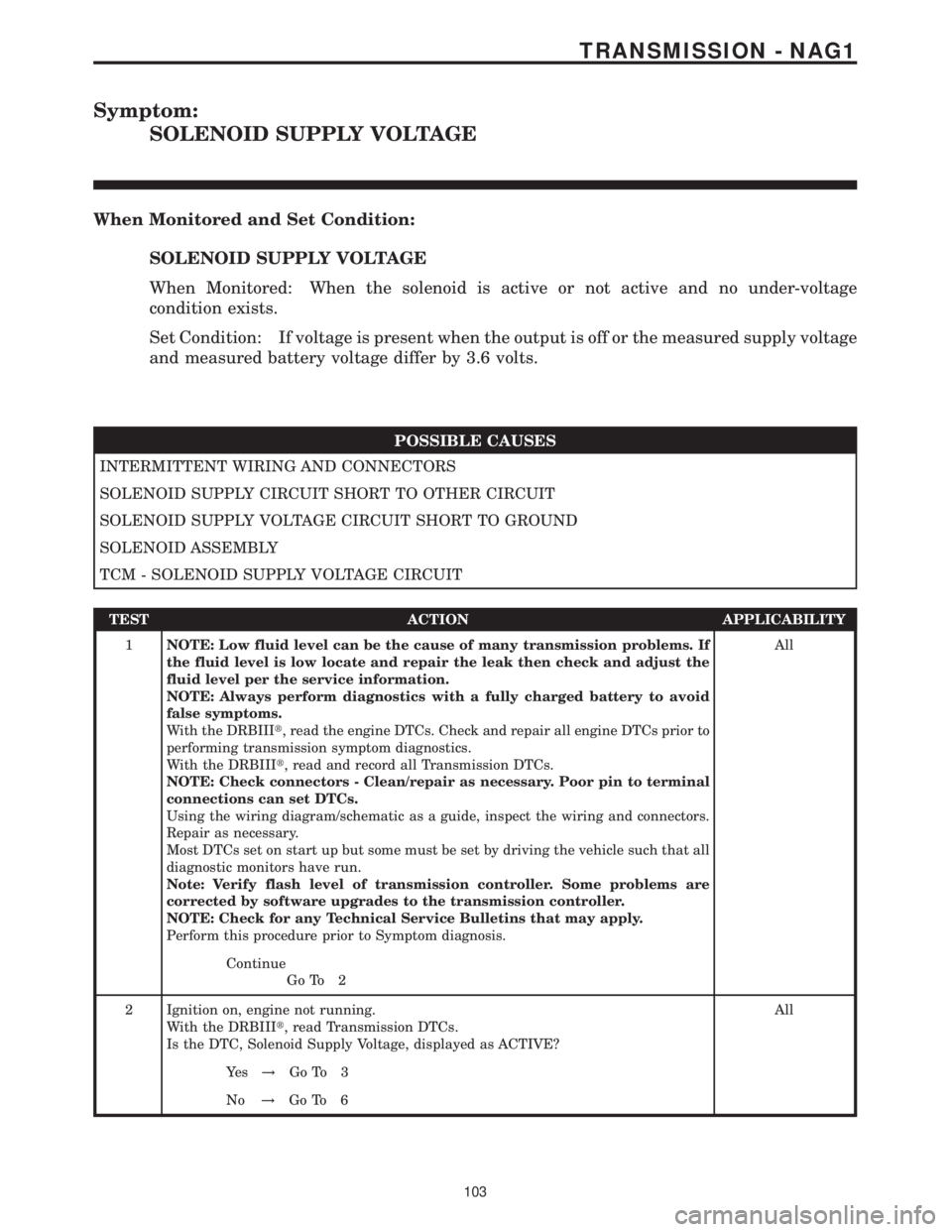
Symptom:
SOLENOID SUPPLY VOLTAGE
When Monitored and Set Condition:
SOLENOID SUPPLY VOLTAGE
When Monitored: When the solenoid is active or not active and no under-voltage
condition exists.
Set Condition: If voltage is present when the output is off or the measured supply voltage
and measured battery voltage differ by 3.6 volts.
POSSIBLE CAUSES
INTERMITTENT WIRING AND CONNECTORS
SOLENOID SUPPLY CIRCUIT SHORT TO OTHER CIRCUIT
SOLENOID SUPPLY VOLTAGE CIRCUIT SHORT TO GROUND
SOLENOID ASSEMBLY
TCM - SOLENOID SUPPLY VOLTAGE CIRCUIT
TEST ACTION APPLICABILITY
1NOTE: Low fluid level can be the cause of many transmission problems. If
the fluid level is low locate and repair the leak then check and adjust the
fluid level per the service information.
NOTE: Always perform diagnostics with a fully charged battery to avoid
false symptoms.
With the DRBIIIt, read the engine DTCs. Check and repair all engine DTCs prior to
performing transmission symptom diagnostics.
With the DRBIIIt, read and record all Transmission DTCs.
NOTE: Check connectors - Clean/repair as necessary. Poor pin to terminal
connections can set DTCs.
Using the wiring diagram/schematic as a guide, inspect the wiring and connectors.
Repair as necessary.
Most DTCs set on start up but some must be set by driving the vehicle such that all
diagnostic monitors have run.
Note: Verify flash level of transmission controller. Some problems are
corrected by software upgrades to the transmission controller.
NOTE: Check for any Technical Service Bulletins that may apply.
Perform this procedure prior to Symptom diagnosis.All
Continue
Go To 2
2 Ignition on, engine not running.
With the DRBIIIt, read Transmission DTCs.
Is the DTC, Solenoid Supply Voltage, displayed as ACTIVE?All
Ye s!Go To 3
No!Go To 6
103
TRANSMISSION - NAG1
Page 2292 of 2305
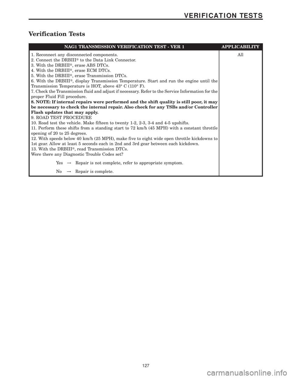
Verification Tests
NAG1 TRANSMISSION VERIFICATION TEST - VER 1 APPLICABILITY
1. Reconnect any disconnected components.
2. Connect the DRBIIItto the Data Link Connector.
3. With the DRBIIIt, erase ABS DTCs.
4. With the DRBIIIt, erase ECM DTCs.
5. With the DRBIIIt, erase Transmission DTCs.
6. With the DRBIIIt, display Transmission Temperature. Start and run the engine until the
Transmission Temperature is HOT, above 43É C (110É F).
7. Check the Transmission fluid and adjust if necessary. Refer to the Service Information for the
proper Fluid Fill procedure.
8. NOTE: If internal repairs were performed and the shift quality is still poor, it may
be necessary to check the internal repair. Also check for any TSBs and/or Controller
Flash updates that may apply.
9. ROAD TEST PROCEDURE
10. Road test the vehicle. Make fifteen to twenty 1-2, 2-3, 3-4 and 4-5 upshifts.
11. Perform these shifts from a standing start to 72 km/h (45 MPH) with a constant throttle
opening of 20 to 25 degrees.
12. With speeds below 40 km/h (25 MPH), make five to eight wide open throttle kickdowns to
1st gear. Allow at least 5 seconds each in 2nd and 3rd gear between each kickdown.
13. With the DRBIIIt, read Transmission DTCs.
Were there any Diagnostic Trouble Codes set?All
Ye s!Repair is not complete, refer to appropriate symptom.
No!Repair is complete.
127
VERIFICATION TESTS