2006 MERCEDES-BENZ SPRINTER engine oil
[x] Cancel search: engine oilPage 2117 of 2305
The receiver/drier cannot be repaired. If the receiv-
er/drier is faulty or damaged, or if an internal failure
of the A/C compressor has occurred, the receiver/drier
must be replaced.
REMOVAL
WARNING: Refer to the applicable warnings and
cautions for this system before performing the fol-
lowing operation (Refer to 24 - HEATING & AIR
CONDITIONING/PLUMBING - WARNINGS) and (Refer
to 24 - HEATING & AIR CONDITIONING/PLUMBING -
CAUTIONS). Failure to follow the warnings and cau-
tions could result in possible personal injury or
death.
(1) Recover the refrigerant from the refrigerant
system (Refer to 24 - HEATING & AIR CONDITION-
ING/PLUMBING - STANDARD PROCEDURE -
REFRIGERANT SYSTEM RECOVERY).
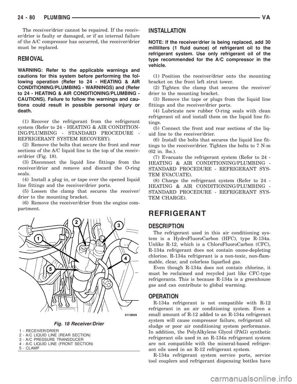
(2) Remove the bolts that secure the front and rear
sections of the A/C liquid line to the top of the receiv-
er/drier (Fig. 18).
(3) Disconnect the liquid line fittings from the
receiver/drier and remove and discard the O-ring
seals.
(4) Install a plug in, or tape over the opened liquid
line fittings and the receiver/drier ports.
(5) Loosen the clamp that secures the receiver/
drier to the mounting bracket.
(6) Remove the receiver/drier from the engine com-
partment.
INSTALLATION
NOTE: If the receiver/drier is being replaced, add 30
milliliters (1 fluid ounce) of refrigerant oil to the
refrigerant system. Use only refrigerant oil of the
type recommended for the A/C compressor in the
vehicle.
(1) Position the receiver/drier onto the mounting
bracket on the front left strut tower.
(2) Tighten the clamp that secures the receiver/
drier to the mounting bracket.
(3) Remove the tape or plugs from the liquid line
fittings and the receiver/drier ports.
(4) Lubricate new rubber O-ring seals with clean
refrigerant oil and install them on the liquid line fit-
tings.
(5) Connect the front and rear sections of the liq-
uid line to the receiver/drier.
(6) Install the bolts that secures the liquid line fit-
tings to the receiver/drier. Tighten the bolts to 7 N´m
(62 in. lbs.).
(7) Evacuate the refrigerant system (Refer to 24 -
HEATING & AIR CONDITIONING/PLUMBING -
STANDARD PROCEDURE - REFRIGERANT SYS-
TEM EVACUATE).
(8) Charge the refrigerant system (Refer to 24 -
HEATING & AIR CONDITIONING/PLUMBING -
STANDARD PROCEDURE - REFRIGERANT SYS-
TEM CHARGE).
REFRIGERANT
DESCRIPTION
The refrigerant used in this air conditioning sys-
tem is a HydroFluoroCarbon (HFC), type R-134a.
Unlike R-12, which is a ChloroFluoroCarbon (CFC),
R-134a refrigerant does not contain ozone-depleting
chlorine. R-134a refrigerant is a non-toxic, non-flam-
mable, clear, and colorless liquefied gas.
Even though R-134a does not contain chlorine, it
must be reclaimed and recycled just like CFC-type
refrigerants. This is because R-134a is a greenhouse
gas and can contribute to global warming.
OPERATION
R-134a refrigerant is not compatible with R-12
refrigerant in an air conditioning system. Even a
small amount of R-12 added to an R-134a refrigerant
system will cause compressor failure, refrigerant oil
sludge or poor air conditioning system performance.
In addition, the PolyAlkylene Glycol (PAG) synthetic
refrigerant oils used in an R-134a refrigerant system
are not compatible with the mineral-based refriger-
ant oils used in an R-12 refrigerant system.
R-134a refrigerant system service ports, service
tool couplers and refrigerant dispensing bottles have
Fig. 18 Receiver/Drier
1 - RECEIVER/DRIER
2 - A/C LIQUID LINE (REAR SECTION)
3 - A/C PRESSURE TRANSDUCER
4 - A/C LIQUID LINE (FRONT SECTION)
5 - CLAMP
24 - 80 PLUMBINGVA
Page 2118 of 2305
all been designed with unique fittings to ensure that
an R-134a system is not accidentally contaminated
with the wrong refrigerant (R-12). There are also
labels posted in the engine compartment of the vehi-
cle and on the compressor identifying to service tech-
nicians that the air conditioning system is equipped
with R-134a.
REFRIGERANT OIL
DESCRIPTION
The refrigerant oil used in R-134a refrigerant sys-
tems is a synthetic-based, PolyAlkylene Glycol (PAG),
wax-free lubricant. Mineral-based R-12 refrigerant
oils are not compatible with PAG oils, and should
never be introduced to an R-134a refrigerant system.
There are different PAG oils available, and each
contains a different additive package. The A/C com-
pressors for this vehicle are designed to use an ND-8
PAG refrigerant oil. Use only the refrigerant oil of
this type to service the refrigerant system.
OPERATION
After performing any refrigerant recovery or recy-
cling operation, always replenish the refrigerant sys-
tem with the same amount of the recommended
refrigerant oil as was removed. Too little refrigerant
oil can cause compressor damage, and too much can
reduce air conditioning system performance.
PAG refrigerant oil is much more hygroscopic than
mineral oil, and will absorb any moisture it comes
into contact with, even moisture in the air. The PAG
oil container should always be kept tightly capped
until it is ready to be used. After use, recap the oil
container immediately to prevent moisture contami-
nation.
STANDARD PROCEDURE
REFRIGERANT OIL LEVEL
When an A/C system is assembled at the factory,
all components except the compressor are refrigerant
oil free. After the refrigerant system has been
charged and operated, the refrigerant oil in the com-
pressor is dispersed throughout the refrigerant sys-
tem. The receiver-drier, evaporator, condenser, and
compressor will each retain a significant amount of
the needed refrigerant oil.
It is important to have the correct amount of oil in
the refrigerant system. This ensures proper lubrica-
tion of the A/C compressor. Too little oil will result in
damage to the A/C compressor. Too much oil will
reduce the cooling capacity of the A/C system.
It will not be necessary to check the oil level in the
A/C compressor or to add oil, unless there has been
an oil loss. An oil loss may occur due to a rupture orleak from a refrigerant line, a connector fitting, a
component, or a component seal. If a leak occurs, add
30 milliliters (1 fluid ounce) of refrigerant oil to the
refrigerant system after the repair has been made.
Refrigerant oil loss will be evident at the leak point
by the presence of a wet, shiny surface around the
leak.
Refrigerant oil must be added when a receiver/
drier, A/C evaporator, or A/C condenser are replaced.
See the Refrigerant Oil Capacities chart. When an
A/C compressor is replaced, the refrigerant oil must
be drained from the old compressor and measured.
Drain all of the refrigerant oil from the new compres-
sor, then fill the new compressor with the same
amount of refrigerant oil that was drained out of the
old compressor.
REFRIGERANT OIL CAPACITIES
Component ml fl oz
Total A/C System Fill 410 13.9
Receiver/Drier 30 1.0
A/C Condenser 30 1.0
A/C Evaporator 60 2.0
A/C CompressorDrain and measure the oil
from the old compressor -
see text.
SUCTION LINE
REMOVAL
WARNING: Refer to the applicable warnings and
cautions for this system before performing the fol-
lowing operation (Refer to 24 - HEATING & AIR
CONDITIONING/PLUMBING - WARNINGS) and (Refer
to 24 - HEATING & AIR CONDITIONING/PLUMBING -
CAUTIONS). Failure to follow the warnings and cau-
tions could result in possible personal injury or
death.
(1) Recover the refrigerant system. (Refer to 24 -
HEATING & AIR CONDITIONING/PLUMBING -
STANDARD PROCEDURE - REFRIGERANT SYS-
TEM RECOVERY)
(2) Disconnect and isolate the negative battery
cable.
(3) Remove the routing clip retaining nut and dis-
engage the metal routing clip from the A/C suction
line.
(4) Disengage the plastic routing clip located near
the A/C expansion valve from the A/C suction line.
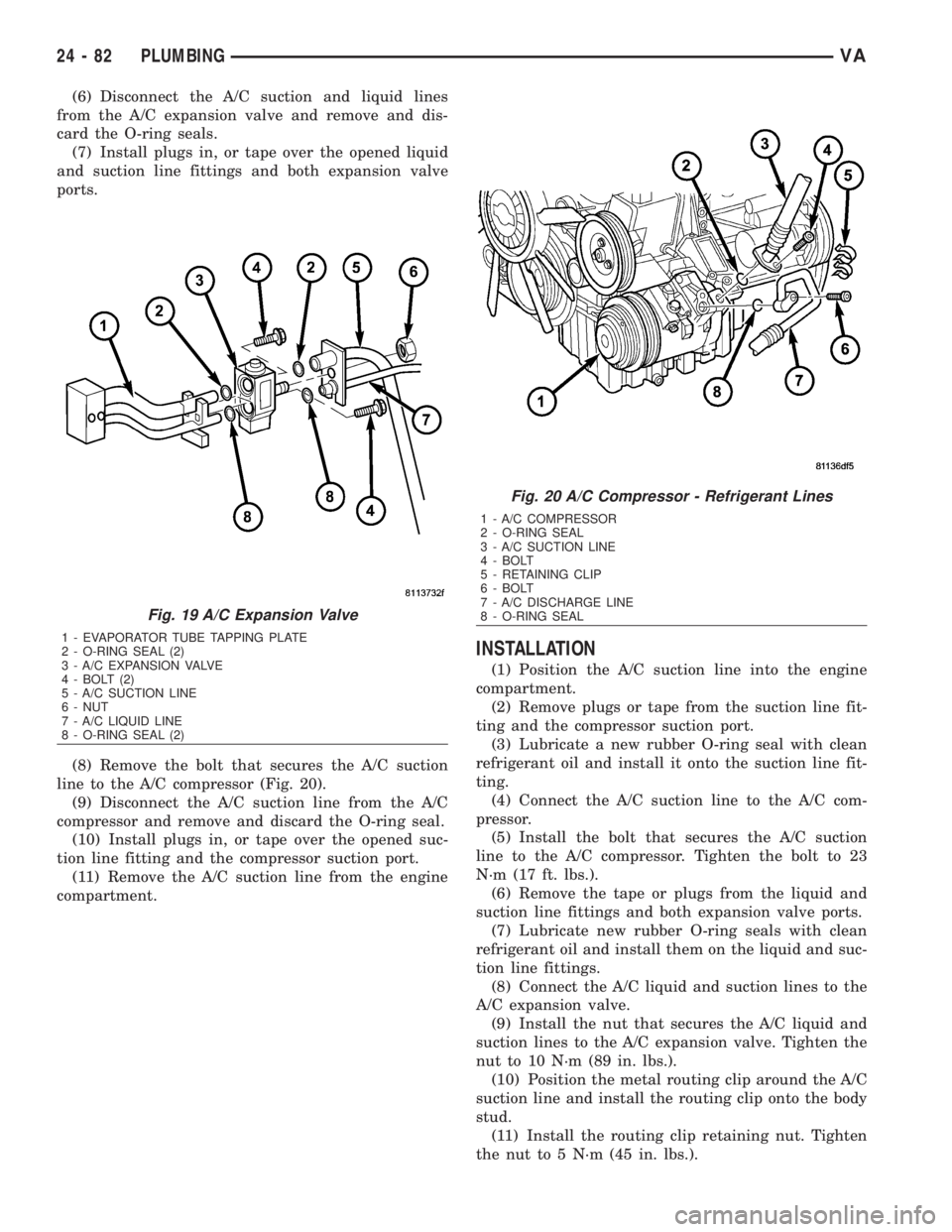
(5) Remove the nut that secures the A/C suction
and liquid lines to the stud on the A/C expansion
valve (Fig. 19).
VAPLUMBING 24 - 81
Page 2119 of 2305
(6) Disconnect the A/C suction and liquid lines
from the A/C expansion valve and remove and dis-
card the O-ring seals.
(7) Install plugs in, or tape over the opened liquid
and suction line fittings and both expansion valve
ports.
(8) Remove the bolt that secures the A/C suction
line to the A/C compressor (Fig. 20).
(9) Disconnect the A/C suction line from the A/C
compressor and remove and discard the O-ring seal.
(10) Install plugs in, or tape over the opened suc-
tion line fitting and the compressor suction port.
(11) Remove the A/C suction line from the engine
compartment.
INSTALLATION
(1) Position the A/C suction line into the engine
compartment.
(2) Remove plugs or tape from the suction line fit-
ting and the compressor suction port.
(3) Lubricate a new rubber O-ring seal with clean
refrigerant oil and install it onto the suction line fit-
ting.
(4) Connect the A/C suction line to the A/C com-
pressor.
(5) Install the bolt that secures the A/C suction
line to the A/C compressor. Tighten the bolt to 23
N´m (17 ft. lbs.).
(6) Remove the tape or plugs from the liquid and
suction line fittings and both expansion valve ports.
(7) Lubricate new rubber O-ring seals with clean
refrigerant oil and install them on the liquid and suc-
tion line fittings.
(8) Connect the A/C liquid and suction lines to the
A/C expansion valve.
(9) Install the nut that secures the A/C liquid and
suction lines to the A/C expansion valve. Tighten the
nut to 10 N´m (89 in. lbs.).
(10) Position the metal routing clip around the A/C
suction line and install the routing clip onto the body
stud.
(11) Install the routing clip retaining nut. Tighten
the nut to 5 N´m (45 in. lbs.).
Fig. 19 A/C Expansion Valve
1 - EVAPORATOR TUBE TAPPING PLATE
2 - O-RING SEAL (2)
3 - A/C EXPANSION VALVE
4 - BOLT (2)
5 - A/C SUCTION LINE
6 - NUT
7 - A/C LIQUID LINE
8 - O-RING SEAL (2)
Fig. 20 A/C Compressor - Refrigerant Lines
1 - A/C COMPRESSOR
2 - O-RING SEAL
3 - A/C SUCTION LINE
4 - BOLT
5 - RETAINING CLIP
6 - BOLT
7 - A/C DISCHARGE LINE
8 - O-RING SEAL
24 - 82 PLUMBINGVA
Page 2141 of 2305
CABIN HEATER
TABLE OF CONTENTS
page page
CABIN HEATER
DESCRIPTION........................104
OPERATION..........................104
DIAGNOSIS AND TESTING
SUPPLEMENTAL CABIN HEATER........104
EXHAUST TUBE
REMOVAL............................105
INSTALLATION........................106
FUEL DOSING PUMP
DESCRIPTION........................106
OPERATION..........................106
REMOVAL............................106
INSTALLATION........................107
FUEL LINE
STANDARD PROCEDURE
CLEANING.........................107REMOVAL............................108
INSTALLATION........................109
HEATER UNIT
REMOVAL
HEATER UNIT.......................110
WIRE HARNESS.....................110
INSTALLATION
HEATER UNIT.......................110
WIRE HARNESS.....................111
INLET HOSE
REMOVAL............................111
INSTALLATION........................112
CABIN HEATER
DESCRIPTION
Vehicles equipped with the diesel engine are also
equipped with a supplemental cabin heater. This
cabin heater is mounted under the vehicle and oper-
ates similar to an oil fired furnace. The heater burns
small amounts of fuel to provide additional heat to
the coolant. Coolant is routed from the engine, to the
supplemental cabin heater and then to the front
heater core. This provides additional heat to the pas-
senger compartment. The supplemental cabin heater
system is interfaced to the vehicles on-board com-
puter systems and DRBIIItdiagnostics.
The supplemental cabin heater has an electronic
control module that monitors the heat output of the
heater. The cabin heater operates at full load (5 kW),
half load or idle mode (no additional heat) depending
on engine coolant temperature.
OPERATION
The supplemental cabin heater is activated by
using the temperature control on the A/C-heater con-
trol. The supplemental cabin heater is activated
when the temperature control is set to/or above the
upper set point. The supplemental cabin heater can
operate in a full or partial load range as well as an
idle mode, all dependent on the engine coolant tem-
perature. The heater unit will also turn off if the
temperature control is set to less than the lower set
point. The supplemental cabin heater can take up to
three minutes to completely shut down when eitherthe heater temperature is set below the lower set
point or the vehicle ignition is turned off.
The supplemental cabin heater only operates when
the engine is running, the mileage exceeds 8 kilome-
ter (5 mph) and the fuel tank volume exceeds 1/8 of a
tank. The heater should start if the coolant temper-
ature is below 40É C (104É F).
NOTE: Do not apply a strong vacuum directly on
the supplemental cabin heater exhaust line. Place
the vacuum within 75 mm (3 inches) of the exhaust
port. Too strong of a vacuum can prevent the heater
from starting. The heater control module monitors
the blower speed and combustion during its start-
up.
DIAGNOSIS AND TESTING
SUPPLEMENTAL CABIN HEATER
Refer to the Symptoms Diagnosis table for basic
checks of the diesel fueled supplemental cabin heater.
24 - 104 CABIN HEATERVA
Page 2151 of 2305
(4) Connect the wiring harness connector to the
CCV heater (Fig. 1).
(5) Install the turbocharger heat shield.
(6) Connect the negative battery cable.
CRANKCASE VENTILATION
BREATHER
DESCRIPTION
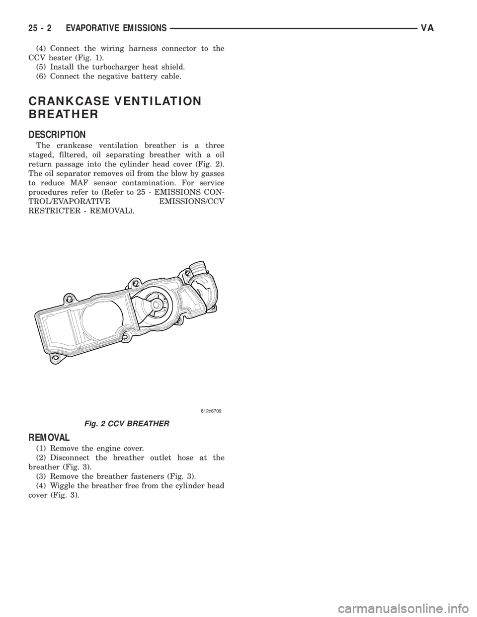
The crankcase ventilation breather is a three
staged, filtered, oil separating breather with a oil
return passage into the cylinder head cover (Fig. 2).
The oil separator removes oil from the blow by gasses
to reduce MAF sensor contamination. For service
procedures refer to (Refer to 25 - EMISSIONS CON-
TROL/EVAPORATIVE EMISSIONS/CCV
RESTRICTER - REMOVAL).
REMOVAL
(1) Remove the engine cover.
(2) Disconnect the breather outlet hose at the
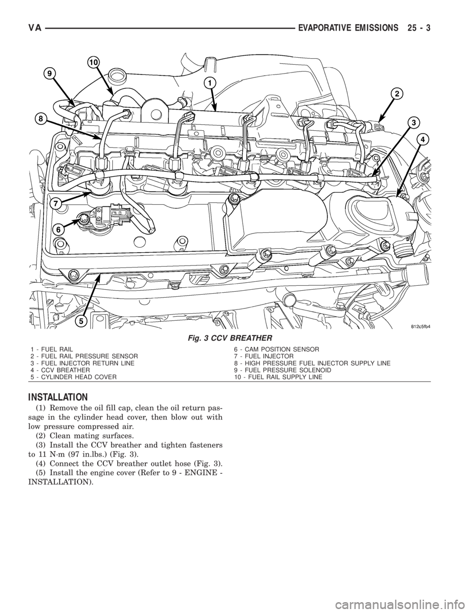
breather (Fig. 3).
(3) Remove the breather fasteners (Fig. 3).
(4) Wiggle the breather free from the cylinder head
cover (Fig. 3).
Fig. 2 CCV BREATHER
25 - 2 EVAPORATIVE EMISSIONSVA
Page 2152 of 2305
INSTALLATION
(1) Remove the oil fill cap, clean the oil return pas-
sage in the cylinder head cover, then blow out with
low pressure compressed air.
(2) Clean mating surfaces.
(3) Install the CCV breather and tighten fasteners
to 11 N´m (97 in.lbs.) (Fig. 3).
(4) Connect the CCV breather outlet hose (Fig. 3).
(5) Install the engine cover (Refer to 9 - ENGINE -
INSTALLATION).
Fig. 3 CCV BREATHER
1 - FUEL RAIL 6 - CAM POSITION SENSOR
2 - FUEL RAIL PRESSURE SENSOR 7 - FUEL INJECTOR
3 - FUEL INJECTOR RETURN LINE 8 - HIGH PRESSURE FUEL INJECTOR SUPPLY LINE
4 - CCV BREATHER 9 - FUEL PRESSURE SOLENOID
5 - CYLINDER HEAD COVER 10 - FUEL RAIL SUPPLY LINE
VAEVAPORATIVE EMISSIONS 25 - 3
Page 2158 of 2305
INDEX
ABS INDICATOR.......................8J-9ACCELERATOR PEDAL POSITION SENSOR. . . 14-32
ACCESSORY SWITCH BEZEL............23-56
ADR INDICATOR.....................8J-10
AIR CLEANER ELEMENT................9-21
AIR CLEANER HOUSING................9-21
AIR FILTER ....................24-45, 24-58
AIR OUTLET TEMPERATURE SENSOR....24-16
AIR OUTLETS.......................24-45
AIRBAG CONTROL MODULE.............8O-8
AIRBAG INDICATOR...................8J-11
ALB CONTROLLER....................5-16
ALB LEVER..........................5-16
AMBIENT TEMPERATURE INDICATOR.....8J-11
AMBIENT TEMPERATURE SENSOR.......24-17
ANTENNA BODY & CABLE..............8A-1
ARMREST..........................23-79
ASH RECEIVER......................23-57
ASH RECEIVER / CIGAR LIGHTER LAMP
UNIT..............................8L-30
ASSIST HANDLE.....................23-71
AUDIO..............................8A-1
AUTOMATIC TRANSMISSION NAG1 -
SERVICE INFORMATION................21-3
A - PILLAR TRIM.....................23-70
A / C CLUTCH RELAY.................24-24
A / C COMPRESSOR CLUTCH COIL.......24-12
A / C COMPRESSOR CLUTCH............24-8
A / C COMPRESSOR..................24-66
A / C CONDENSER COVER.............24-52
A / C CONDENSER FAN RELAY..........24-26
A / C CONDENSER HOUSING...........24-52
A / C CONDENSER....................24-69
A / C CONTROL MODULE..............24-28
A / C DISCHARGE LINE................24-71
A / C EVAPORATOR COVER.............24-55
A / C EVAPORATOR HOUSING...........24-55
A / C EVAPORATOR...................24-72
A / C EXPANSION VALVE...............24-73
A / C HEATER CONTROL...............24-12
A / C HIGH PRESSURE SWITCH.........24-30
A / C LOW PRESSURE SWITCH.........24-32
A / C PRESSURE TRANSDUCER.........24-14
BACKLITE - BULKHEAD TRIM PANEL.....23-84
BACKUP LAMP BULB..................8L-5
BASECOAT / CLEARCOAT FINISH........23-77
BATTERY CABLES....................8F-14
BATTERY HOLDDOWN.................8F-13
BATTERY SYSTEM.....................8F-1
BATTERY TRAY......................8F-16
BATTERY............................8F-6
BEARINGS - DIFFERENTIAL CASE.........3-38
BEARING / SEAL - AXLE HUB............3-28
BEARING / SEAL - AXLE................3-24
BELT TENSIONERS.....................7-5
BLOWER MOTOR RELAY...............24-33
BLOWER MOTOR RESISTOR............24-17
BLOWER MOTOR SWITCH........24-19, 24-35
BLOWER MOTOR...............24-47, 24-58
BODY...............................23-1
BOOST PRESSURE SENSOR............14-33
BRAKE INDICATOR...................8J-12
BRAKE LAMP SWITCH.................8L-6
BRAKE LINES.........................5-8
BRAKE PADS / SHOES...................5-8
BRAKE WEAR INDICATOR..............8J-13
BRAKES - ABS........................5-30
BRAKES - BASE........................5-2
BRAKE / PARK LAMP BULB.............8L-7
BULKHEAD TRIM PANEL...............23-72
BUMPERS...........................13-1
BUSHINGS............................2-3
B - PILLAR TRIM.....................23-71
CABIN HEATER.....................24-104
CABLE TENSIONER....................5-24
CABLE..............................8P-2
CABLES.............................5-24
CAMSHAFT POSITION SENSOR..........14-33
CAMSHAFT(S)........................9-28
CARGO LAMP SWITCH................8L-31
CARGO / DOME LAMP BULB............8L-30
CARGO / DOME LAMP UNIT............8L-31
CARPETS AND FLOOR MATS...........23-72
CATALYTIC CONVERTER
................11-3
CENTER BEARING
......................3-9
CENTER HIGH MOUNTED STOP LAMP BULB. . . 8L-8CENTER HIGH MOUNTED STOP LAMP UN.....8L-8
CENTER ROLLER ARM
................23-36CENTER TRACK......................23-37
CENTRAL TIMER MODULE..............8E-1
CHARGE AIR COOLER AND PLUMBING....11-4
CHARGING INDICATOR................8J-14
CHARGING SYSTEM..................8F-17
CHECK VALVE.......................8R-11
CHECK.......................23-13, 23-23
CHIME / BUZZER......................8B-1
CIGAR LIGHTER OUTLET............8W-97-1
CIRCUIT BREAKER.................8W-97-2
CLEARANCE LAMP BULB...............8L-9
CLEARANCE LAMP UNIT................8L-9
CLOCK.............................8J-14
CLOCKSPRING......................8O-12
CLUSTER BEZEL.....................23-55
COLUMN............................19-4
CONNECTOR.......................Intro.-9
CONNECTOR/GROUND/SPLICE
LOCATION........................8W-91-1
CONTROLLER ANTILOCK BRAKE.........8E-3
COOLANT LEVEL SENSOR...............7-13
COOLANT LOW INDICATOR.............8J-15
COOLANT............................7-9
COOLING.............................7-1
COWL TRIM........................23-73
CRANKCASE VENTILATION BREATHER......25-2
CRANKCASE VENTILATION HEATER.......25-1
CRANKSHAFT OIL SEAL - FRONT.........9-42
CRANKSHAFT OIL SEAL - REAR..........9-41
CRANKSHAFT POSITION SENSOR........14-35
CRANKSHAFT........................9-39
CUP HOLDER........................23-57
CYLINDER HEAD COVER(S).............9-33
CYLINDER HEAD......................9-22
DAYTIME RUNNING LAMP RELAY.......8L-10
DEFROSTER DUCTS..................24-47
DIFFERENTIAL........................3-31
DIODE............................Intro.-9
DISC BRAKE CALIPER ADAPTER.........5-14
DISC BRAKE CALIPERS.................5-11
DOME LAMP / INTRUSION SENSOR
BULB..............................8L-33
DOME LAMP / INTRUSION SENSOR......8L-33
DOME / READING LAMP BULB..........8L-32
DOME / READING LAMP UNIT..........8L-32
DOOR GLASS............23-15, 23-30, 23-46
DOOR JAMB SWITCH.................8L-34
DOOR LOCK MOTOR...................8N-1
DOOR OPENING SEALS................23-90
DOOR........................23-14, 23-23
DRIVE BELTS..........................7-5
DRIVER AIRBAG.....................8O-16
DRIVER HEATED SEAT SWITCH.........8G-11
D - PILLAR TRIM.....................23-73
ELECTRIC COOLANT PUMP.............24-75
ELECTRICAL.........................5-30
ELECTROHYDRAULIC UNIT............21-105
ENGINE BLOCK HEATER................7-14
ENGINE BLOCK.......................9-37
ENGINE CONTROL MODULE.............8E-3
ENGINE COOLANT TEMP SENSOR........7-15
ENGINE COOLANT THERMOSTAT.........7-16
ENGINE CRADLE CROSSMEMBER........13-8
ENGINE TEMPERATURE GAUGE.........8J-15
ENGINE..............................9-2
ENTRY / EXIT LAMP BULB.............8L-34
ENTRY / EXIT LAMP UNIT..............8L-35
ESP INDICATOR......................8J-16
EVAPORATOR TEMPERATURE
SENSOR......................24-19, 24-37
EXHAUST GAS RECIRCULATION..........25-4
EXHAUST MANIFOLD..................9-68
EXHAUST PIPE.......................11-3
EXHAUST SYSTEM....................11-1
EXHAUST TUBE.....................24-105
EXTERIOR HANDLE.......23-16, 23-31, 23-35
FAN DRIVE VISCOUS CLUTCH...........7-17
FASTENER IDENTIFICATION...........Intro.-3
FASTENER USAGE...................Intro.-6
FINESSE SANDING / BUFFING & POLISH . . 23-78
FLOOR DISTRIBUTION DUCTS..........24-47
FLUID AND FILTER..................21-131
FLUID CAPACITIES.....................0-5
FLUID COOLER TUBE
.................19-13
FLUID FILL / CHECK LOCATIONS
..........0-5
FLUID RESERVOIR
....................5-15
FLUID TYPES
..........................0-1
FLYWHEEL
...........................9-43FOG LAMP BULB.....................8L-10
FOG LAMP RELAY....................8L-11
FOG LAMP SWITCH...................8L-12
FRAME..............................13-3
FREEWHEELING CLUTCH.............21-135
FRONT BUMPER - STEPS...............13-2
FRONT DOOR INNER BELT
WEATHERSTRIP.....................23-90
FRONT DOOR OUTER BELT
WEATHERSTRIP.....................23-90
FRONT FASCIA.......................13-2
FRONT LAMP UNIT...................8L-13
FRONT POSITION LAMP BULB..........8L-14
FRONT SEAT BELT & RETRACTOR.......8O-20
FRONT SEAT BELT BUCKLE............8O-23
FRONT TURN / PARK / SIDE MARKER
LAMP BULB.........................8L-15
FRONT WHEEL SPEED SENSOR..........5-31
FRONT...............................2-1
FUEL DELIVERY.......................14-6
FUEL DOSING PUMP.................24-106
FUEL DRAIN TUBES..................14-10
FUEL FILL DOOR.....................23-48
FUEL FILTER CLOGGED INDICATOR......8J-17
FUEL FILTER........................14-10
FUEL GAUGE........................8J-17
FUEL INJECTOR.......................14-35
FUEL LEVEL SENDING UNIT / SENSOR....14-28
FUEL LINE.........................24-107
FUEL LINES.........................14-11
FUEL PRESSURE SENSOR.............14-39
FUEL PRESSURE SOLENOID............14-40
FUEL PUMP MODULE.................14-18
FUEL PUMP.........................14-13
FUEL QUANTITY CONTROL VALVE.......14-21
FUEL RAIL PRESSURE SENSOR.........14-12
FUEL RAIL..........................14-22
FUEL SYSTEM........................14-1
FUEL TANK.........................14-23
FUEL TEMPERATURE SENSOR..........14-42
FUSE BLOCK #1...................8W-97-2
FUSE BLOCK #2...................8W-97-3
GAP AND FLUSH.....................23-91
GEAR SELECTOR INDICATOR...........8J-18
GEAR...............................19-7
GEARSHIFT CABLE..................21-138
GEAR - PINION / RING.................3-41
GENERATOR DECOUPLER PULLEY.......8F-19
GENERATOR........................8F-18
GLOVE BOX.........................23-58
GLOW PLUG RELAY....................8I-1
GLOW PLUG..........................8I-1
GRILLE............................23-48
HCU (HYDRAULIC CONTROL UNIT).......5-36
HEADLAMP LEVELING MOTOR..........8L-16
HEADLAMP LEVELING SWITCH.........8L-17
HEADLINER.........................23-73
HEADREST..........................23-79
HEATED GLASS.......................8G-1
HEATED MIRRORS....................8G-9
HEATED SEAT ELEMENT...............8G-12
HEATED SEAT RELAY.................8G-12
HEATED SEAT SENSOR................8G-13
HEATED SEATS ......................8G-10
HEATER CORE.......................24-76
HEATER UNIT......................24-110
HEATING & AIR CONDITIONING..........24-1
HIGH BEAM HEADLAMP BULB..........8L-18
HIGH BEAM INDICATOR...............8J-19
HINGE..................23-17, 23-32, 23-51
HOISTING............................0-5
HOLDING CLUTCH B1................21-143
HOLDING CLUTCH B2................21-148
HOLDING CLUTCHES.................21-141
HOOD.............................23-51
HORN SWITCH.......................8H-1
HORN..............................8H-1
HOSES.............................19-14
HUB / BEARING........................2-4
HVAC HOUSING......................24-48
HYDRAULIC / MECHANICAL..............5-5
IGNITION CONTROL....................8I-1
INLET HOSE........................24-111
INPUT CLUTCH K1
...................21-92
INPUT CLUTCH K2
...................21-97
INPUT CLUTCH K3
..................21-102
INPUT CLUTCHES
....................21-90
INPUT SPEED SENSORS
..............21-153
VAINDEX 1
Description Group-Page Description Group-Page Description Group-Page
Page 2169 of 2305
3.2.5 TRANSMISSION OPERATION AND
SHIFT SCHEDULING
The transmission covered in this manual has
unique shift schedules depending on the tempera-
ture of the transmission oil. The transmission oil
temperature has a decisive effect on the shift qual-
ity of the transmission. The shift schedule is modi-
fied to extend the life of the transmission while
operating under extreme conditions and to improve
driver comfort by modifying shift schedules.
The transmission oil temperature is measured
with a Temperature Sensor on the NAG1 transmis-
sion. The Temperature Sensor is an integral com-
ponent of the Transmission Solenoid assembly. If
the Temperature Sensor is causing a problem, a
DTC will be set in the TCM.
The Transmission Temperature Sensor is wired in
series with the Park /Neutral (P/N) switch. The P/N
switch is also located in the transmission. The trans-
mission temperature is only read by the TCM when
the P/N switch closes while in the R, D position.
When the shifter lever is in the park or neutral
position, the P/N switch opens and the temperature
being displayed is Engine temperature.
AutoStick Feature (If equipped)
This feature allows the driver to manually shift the
transaxle when the shift lever is moved sideways to
the (+ / -) in position D to adjust the shift range.
3.2.6 TRANSMISSION ADAPTIVES -
INITIALIZE AND STORE
Initialize Adaptive -This TCM function should be
used when a new transmission has been placed in
the vehicle. This command will reset the TCM
adaptive to the factory setting.
Store Adaptive -This command should be used
after the vehicle has been test driven by the tech-
nician to store any learned adaptive changes that
occurred during the test drive. During normal op-
eration adaptive are updated every 10 minutes.
Using this command the latest adaptive will be
written to the TCM immediately.
3.3 DIAGNOSTIC TROUBLE CODES
Diagnostic trouble codes (DTC's) are codes stored
by the Transmission Control Module (TCM) and the
Shift Lever Assembly Module (SLA) to help diag-
nose Transmission and Shifter problems. They are
viewed using the DRBIIItscan tool.
Always begin by performing a visual inspection of
the wiring, connectors, cooler lines and the trans-
mission. Any obvious wiring problems or leaks
should be repaired prior to performing any diagnos-
tic test procedures. Some engine driveability prob-lems can be misinterpreted as a transmission prob-
lem. Ensure that the engine is running properly
and that no ECM DTC's are present that could
cause a transmission complaint.
If there is a communication K-ABS,Shifter or
K-TCM circuit problem, trouble codes will not be
accessible until the problem is fixed. The DRBIIIt
will display an appropriate message. The following
is a possible list of causes for a bus problem:
± open or short to ground/battery in K line
circuit.
± internal failure of any module or component
connected to the K line circuit
Each diagnostic trouble code is diagnosed by
following a specific testing sequence. The diagnostic
test procedures contain step-by-step instructions
for determining the cause of a transmission diag-
nostic trouble code. Possible sources of the code are
checked and eliminated one by one. It is not neces-
sary to perform all of the tests in this book to
diagnose an individual code. These tests are based
on the problem being present at the time that the
test is run.
If the TCM records a DTC that will adversely
affect the vehicles transmission, it will request (via
the communication bus) that the ECM illuminate
the Malfunction Indicator Lamp (MIL). All trans-
mission DTC's will be stored in the TCM.
3.3.1 ACTIVE (HARD) CODE
Any Diagnostic Trouble Code (DTC) that is set
whenever the system or component is monitored is
an Active code. This means that the problem is
there every time the TCM checks that system or
component. Some codes will set immediately at
start up and others will require a road test under
specific conditions to set the DTC. It must be
determined if a code is Active (repeatable) or Stored
(Intermittent) before attempting diagnosis.
3.3.2 STORED (INTERMITTENT) CODE
A diagnostic trouble code that is not there every
time the TCM checks the circuit or function is a
Stored (Intermittent) code. Problems that come and
go like this are the most difficult to diagnose, they
must be looked for under the specific conditions
that cause them. If the DTC is reset (after an
ignition cycle) the DTC will be set to Stored (Inter-
mittent) status. A DTC status can be9Active9or
9Stored9(Intermittent). Active is when the DTC is
present in the controller and the transmission is in
the particular mode of operation for that DTC.
Stored means that the DTC occurred at some point,
but is not currently present, or the conditions have
not been right to check for the presence of the
problem, when a DTC is classified as Stored (Inter-
mittent), no TCM reaction is required.
4
GENERAL INFORMATION