2006 MERCEDES-BENZ SPRINTER high beam
[x] Cancel search: high beamPage 922 of 2305

Located between the rear cover and the cluster
hood is the cluster housing. The molded plastic clus-
ter housing serves as the carrier for the cluster elec-
tronic circuit board and circuitry, the cluster
connector receptacles, the gauges, a Light Emitting
Diode (LED) for each cluster indicator and general
illumination lamp, the multi-function indicator LCD
unit, electronic tone generators, the cluster overlay,
the gauge pointers, the multi-function indicator
switches and the four switch push buttons.
The cluster overlay is a laminated plastic unit. The
dark, visible, outer surface of the overlay is marked
with all of the gauge dial faces and graduations, but
this layer is also translucent. The darkness of this
outer layer prevents the cluster from appearing clut-
tered or busy by concealing the cluster indicators
that are not illuminated, while the translucence of
this layer allows those indicators and icons that are
illuminated to be readily visible. The underlying
layer of the overlay is opaque and allows light from
the LED for each of the various indicators and illu-
mination lamps behind it to be visible through the
outer layer of the overlay only through predeter-
mined cutouts. A rectangular opening in the overlay
at the base of the speedometer provides a window
through which the illuminated multi-function indica-
tor LCD unit can be viewed.
Several versions of the EMIC module are offered
on this model. These versions accommodate all of the
variations of optional equipment and regulatory
requirements for the various markets in which the
vehicle will be offered. The microprocessor-based
EMIC utilizes integrated circuitry, Electrically Eras-
able Programmable Read Only Memory (EEPROM)
type memory storage, information carried on the
Controller Area Network (CAN) data bus, along with
several hard wired analog and multiplexed inputs to
monitor systems, sensors and switches throughout
the vehicle.
In response to those inputs, the hardware and soft-
ware of the EMIC allow it to control and integrate
many electronic functions and features of the vehicle
through both hard wired outputs and the transmis-
sion of electronic message outputs to other electronic
modules in the vehicle over the CAN data bus. (Refer
to 8 - ELECTRICAL/ELECTRONIC CONTROL
MODULES/COMMUNICATION - DESCRIPTION -
CAN BUS).
Besides typical instrument cluster gauge and indi-
cator support, the electronic functions and features
that the EMIC supports or controls include the fol-
lowing:
²Active Service System- In vehicles equipped
with the Active Service SYSTem (ASSYST) engine oil
maintenance indicator option, the EMIC electronic
circuit board includes a second dedicated micropro-
cessor. This second microprocessor evaluates various
data including time, mileage, and driving conditionsto calculate the required engine oil service intervals,
and provides both visual and audible alerts to the
vehicle operator when certain engine oil maintenance
services are required.
²Audible Warnings- The EMIC electronic cir-
cuit board is equipped with an audible tone generator
and programming that allows it to provide various
audible alerts to the vehicle operator, including buzz-
ing and chime tones. An audible contactless elec-
tronic relay is also soldered onto the circuit board to
produce audible clicks that is synchronized with turn
signal indicator flashing to emulate the sounds of a
conventional turn signal or hazard warning flasher.
These audible clicks can occur at one of two rates to
emulate both normal and bulb-out turn or hazard
flasher operation. (Refer to 8 - ELECTRICAL/
CHIME/BUZZER - DESCRIPTION).
²Panel Lamps Dimming Control- The EMIC
provides a hard wired 12-volt Pulse-Width Modulated
(PWM) output that synchronizes the dimming level
of all panel lamps dimmer controlled lamps with that
of the cluster general illumination lamps and multi-
function indicator.
The EMIC houses four analog gauges and has pro-
visions for up to nineteen indicators (Fig. 3). The
EMIC includes the following analog gauges:
²Coolant Temperature Gauge
²Fuel Gauge
²Speedometer
²Tachometer
The EMIC includes provisions for the following
indicators (Fig. 3):
²Airbag (SRS) Indicator
²Antilock Brake System (ABS) Indicator
²Brake Indicator
²Brake Wear Indicator
²Charging Indicator
²Clogged Fuel Filter Indicator
²Constant Engine Speed (ADR) Indicator
²Coolant Low Indicator
²Electronic Stability Program (ESP) Indica-
tor
²High Beam Indicator
²Low Fuel Indicator
²Malfunction Indicator Lamp (MIL)
²Multi-Function Indicator (LCD)
²Park Brake Indicator
²Seatbelt Indicator
²Traction Control (ASR) Indicator
²Traction Control (ASR) Malfunction Indica-
tor
²Turn Signal (Right and Left) Indicators
²Washer Fluid Indicator
²Wait-To-Start Indicator
²Water-In-Fuel Indicator
VAINSTRUMENT CLUSTER 8J - 3
Page 923 of 2305
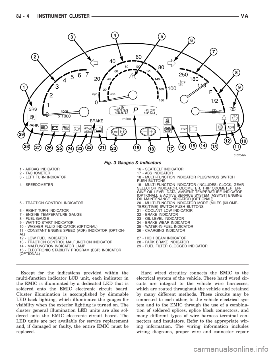
Except for the indications provided within the
multi-function indicator LCD unit, each indicator in
the EMIC is illuminated by a dedicated LED that is
soldered onto the EMIC electronic circuit board.
Cluster illumination is accomplished by dimmable
LED back lighting, which illuminates the gauges for
visibility when the exterior lighting is turned on. The
cluster general illumination LED units are also sol-
dered onto the EMIC electronic circuit board. The
LED units are not available for service replacement
and, if damaged or faulty, the entire EMIC must be
replaced.Hard wired circuitry connects the EMIC to the
electrical system of the vehicle. These hard wired cir-
cuits are integral to the vehicle wire harnesses,
which are routed throughout the vehicle and retained
by many different methods. These circuits may be
connected to each other, to the vehicle electrical sys-
tem and to the EMIC through the use of a combina-
tion of soldered splices, splice block connectors, and
many different types of wire harness terminal con-
nectors and insulators. Refer to the appropriate wir-
ing information. The wiring information includes
wiring diagrams, proper wire and connector repair
Fig. 3 Gauges & Indicators
1 - AIRBAG INDICATOR 16 - SEATBELT INDICATOR
2 - TACHOMETER 17 - ABS INDICATOR
3 - LEFT TURN INDICATOR 18 - MULTI-FUNCTION INDICATOR PLUS/MINUS SWITCH
PUSH BUTTONS
4 - SPEEDOMETER 19 - MULTI-FUNCTION INDICATOR (INCLUDES: CLOCK, GEAR
SELECTOR INDICATOR, ODOMETER, TRIP ODOMETER, EN-
GINE OIL LEVEL DATA, AMBIENT TEMPERATURE INDICATOR
[OPTIONAL], & ACTIVE SERVICE SYSTEM [ASSYST] ENGINE
OIL MAINTENANCE INDICATOR [OPTIONAL])
5 - TRACTION CONTROL INDICATOR 20 - MULTI-FUNCTION INDICATOR MODE (MILES [KILOME-
TERS]/TIME) SWITCH PUSH BUTTONS
6 - RIGHT TURN INDICATOR 21 - COOLANT LOW INDICATOR
7 - ENGINE TEMPERATURE GAUGE 22 - BRAKE INDICATOR
8 - FUEL GAUGE 23 - OIL LEVEL INDICATOR
9 - WAIT-TO-START INDICATOR 24 - BRAKE WEAR INDICATOR
10 - WASHER FLUID INDICATOR (OPTIONAL) 25 - WATER-IN-FUEL INDICATOR
11 - CONSTANT ENGINE SPEED (ADR) INDICATOR (OPTION-
AL)26 - CHARGING INDICATOR
12 - LOW FUEL INDICATOR 27 - HIGH BEAM INDICATOR
13 - TRACTION CONTROL MALFUNCTION INDICATOR 28 - PARK BRAKE INDICATOR
14 - MALFUNCTION INDICATOR LAMP 29 - FUEL FILTER CLOGGED INDICATOR
15 - ELECTRONIC STABILITY PROGRAM (ESP) INDICATOR
(OPTIONAL)
8J - 4 INSTRUMENT CLUSTERVA
Page 925 of 2305

INDICATORS
Indicators are located in various positions within
the EMIC and are all connected to the EMIC elec-
tronic circuit board. The ambient temperature indica-
tor (optional), brake indicator, brake wear indicator,
charging indicator, coolant low indicator, high beam
indicator, low fuel indicator, park brake indicator,
seatbelt indicator, turn signal indicators, and washer
fluid indicator operate based upon hard wired inputs
to the EMIC. The airbag (SRS) indicator is normally
controlled by a hard wired input from the Airbag
Control Module (ACM); however, if the EMIC sees an
abnormal or no input from the ACM, it will automat-
ically turn the airbag indicator On until the hard
wired input from the ACM has been restored. The
Malfunction Indicator Lamp (MIL) is normally con-
trolled by CAN data bus messages from the Engine
Control Module (ECM); however, if the EMIC loses
CAN data bus communication, the EMIC circuitry
will automatically turn the MIL on until CAN data
bus communication is restored. The EMIC uses CAN
data bus messages from the ECM, the ACM, and the
Controller Antilock Brake to control all of the
remaining indicators.
The various EMIC indicators are controlled by dif-
ferent strategies; some receive battery feed from the
EMIC circuitry and have a switched ground, while
others are grounded through the EMIC circuitry and
have a switched battery feed. However, all indicators
are completely controlled by the EMIC microproces-
sor based upon various hard wired and electronic
message inputs. Except for the indications provided
by the multi-function indicator Liquid Crystal Dis-
play (LCD) unit, all indicators are illuminated at a
fixed intensity, which is not affected by the selected
illumination intensity of the EMIC general illumina-
tion lamps.
The hard wired indicator inputs may be diagnosed
using conventional diagnostic methods. However,
proper testing of the EMIC circuitry and the CAN
bus message controlled indicators requires the use of
a diagnostic scan tool. Refer to the appropriate diag-
nostic information. Specific details of the operation
for each indicator may be found elsewhere in this
service information.
CLUSTER ILLUMINATION
The EMIC has several general illumination lamps
that are illuminated when the exterior lighting is
turned on with the multi-function switch. The illumi-
nation intensity of these lamps is adjusted by a dim-
ming level input received from the multi-function
indicator ª+º (plus) and ª±º (minus) switch push but-
tons that extend through the lower edge of the clus-
ter lens below the right end of the multi-function
indicator. When the exterior lighting is turned Off,
the display is illuminated at maximum brightness.
When the exterior lighting is turned On and thetransmission gear selector is in the Park position,
depressing the plus switch push button brightens the
display lighting, and depressing the minus switch
push button dims the display lighting. The EMIC
also provides a Pulse-Width Modulated (PWM) panel
lamps dimmer output that can be used to synchro-
nize the illumination lighting levels of external illu-
mination lamps (up to about 23 to 30 watts) with
that of the EMIC.
The hard wired multi-function switch input and
the EMIC panel lamps dimmer output may be diag-
nosed using conventional diagnostic methods. How-
ever, proper testing of the PWM control of the EMIC
and the electronic dimming level inputs from the
multi-function indicator push buttons requires the
use of a diagnostic scan tool. Refer to the appropriate
diagnostic information.
INPUT AND OUTPUT CIRCUITS
HARD WIRED INPUTS
The hard wired inputs to the EMIC include the fol-
lowing:
NOTE: Final approved circuit names were not yet
available at the time this information was compiled.
²Airbag Indicator Driver
²Ambient Temperature Sensor Signal
(Optional)
²Brake Wear Indicator Sense
²Charging Indicator Driver
²Coolant Level Switch Sense
²Front Door Jamb Switch Sense
²Fuel Level Sensor Signal
²Fused B(+)
²Fused Ignition Switch Output
²High Beam Indicator Driver
²Key-In Ignition Switch Sense
²Left Turn Signal
²Park Brake Switch Sense
²Right Turn Signal
²Seat Belt Switch Sense
²Washer Fluid Switch Sense (Optional)
Refer to the appropriate wiring information for
additional details.
HARD WIRED OUTPUTS
The hard wired outputs of the EMIC include the
following:
²Engine Running Relay Control
²Panel Lamps Driver
Refer to the appropriate wiring information for
additional details.
8J - 6 INSTRUMENT CLUSTERVA
Page 938 of 2305

required. Refer to the appropriate diagnostic infor-
mation.
HIGH BEAM INDICATOR
DESCRIPTION
A high beam indicator is standard equipment on
all instrument clusters. The high beam indicator is
located near the lower edge of the instrument cluster,
to the left of the multi-function indicator display. The
high beam indicator consists of the International
Control and Display Symbol icon for ªHigh Beamº
imprinted within a rectangular cutout in the opaque
layer of the instrument cluster overlay. The dark
outer layer of the overlay prevents the indicator from
being clearly visible when it is not illuminated. A
blue Light Emitting Diode (LED) behind the cutout
in the opaque layer of the overlay causes the icon to
appear silhouetted against a blue field through the
translucent outer layer of the overlay when the indi-
cator is illuminated from behind by the LED, which
is soldered onto the instrument cluster electronic cir-
cuit board. The high beam indicator is serviced as a
unit with the instrument cluster.
OPERATION
The high beam indicator gives an indication to the
vehicle operator whenever the headlamp high beams
are illuminated. This indicator is controlled by a
transistor on the instrument cluster circuit board
based upon cluster programming and a hard wired
input from the multi-function switch. The high beam
indicator Light Emitting Diode (LED) is completely
controlled by the instrument cluster logic circuit, and
that logic will allow this indicator to operate when-
ever the instrument cluster receives battery current
on the fused B(+) circuit. Therefore, the LED can be
illuminated regardless of the ignition switch position.
The LED only illuminates when it is provided a path
to ground by the instrument cluster transistor. The
instrument cluster will turn on the high beam indi-
cator for the following reasons:
²Bulb Test- Each time the ignition switch is
turned to the On position the high beam indicator is
illuminated by the cluster for about two seconds as a
bulb test.
²High Beams On Input- Each time the cluster
receives a high beam headlamps-on input from the
multi-function switch, the high beam indicator will
be illuminated. The indicator remains illuminated
until the cluster receives a high beam headlamps-off
input from the multi-function switch.
The instrument cluster continually monitors the
multi-function switch input to determine whether the
high beam indicator should be illuminated or extin-
guished. The multi-function switch and the multi-
function switch input circuit to the instrumentcluster can be diagnosed using conventional diagnos-
tic tools and methods. For proper diagnosis of the
instrument cluster circuitry that controls the high
beam indicator, a diagnostic scan tool is required.
Refer to the appropriate diagnostic information.
LOW FUEL INDICATOR
DESCRIPTION
A low fuel indicator is standard equipment on all
instrument clusters. The low fuel indicator is located
directly below the low end of the fuel gauge scale.
The low fuel indicator consists of a small triangular
cutout in the opaque layer of the instrument cluster
overlay. The dark outer layer of the overlay prevents
the indicator from being clearly visible when it is not
illuminated. An amber Light Emitting Diode (LED)
behind the cutout in the opaque layer of the overlay
causes the triangle to appear in amber through the
translucent outer layer of the overlay when the indi-
cator is illuminated from behind by the LED, which
is soldered onto the instrument cluster electronic cir-
cuit board. The low fuel indicator is serviced as a
unit with the instrument cluster.
OPERATION
The low fuel indicator gives an indication to the
vehicle operator when the level of fuel in the fuel
tank becomes low. This indicator is controlled by a
transistor on the instrument cluster circuit board
based upon cluster programming and a hard wired
input received by the cluster from the fuel level sen-
sor in the fuel tank. The low fuel indicator Light
Emitting Diode (LED) is completely controlled by the
instrument cluster logic circuit, and that logic will
only allow this indicator to operate when the instru-
ment cluster detects that the ignition switch is in the
On position. Therefore, the LED will always be off
when the ignition switch is in any position except
On. The LED only illuminates when it is provided a
path to ground by the instrument cluster transistor.
The instrument cluster will turn on the low fuel indi-
cator for the following reasons:
²Bulb Test- Each time the ignition switch is
turned to the On position the low fuel indicator is
illuminated for about two seconds as a bulb test.
²Fuel Level Sensor Input- Each time the clus-
ter receives an input from the fuel level sensor indi-
cating that the fuel level has reached about 12 liters
(3 gallons) or less, the low fuel indicator is illumi-
nated. The indicator remains illuminated until the
cluster receives an input from the fuel level sensor
indicating that the fuel level is above 12 liters (3 gal-
lons), or until the ignition switch is turned to the Off
position, whichever occurs first.
The fuel level sensor in the fuel tank provides a
hard wired input to the instrument cluster circuitry
VAINSTRUMENT CLUSTER 8J - 19
Page 950 of 2305
LAMPS
TABLE OF CONTENTS
page page
LAMPS/LIGHTING - EXTERIOR............... 1LAMPS/LIGHTING - INTERIOR............... 28
LAMPS / LIGHTING - EXTERIOR
TABLE OF CONTENTS
page page
LAMPS/LIGHTING - EXTERIOR
DESCRIPTION..........................2
OPERATION............................3
SPECIFICATIONS - LAMPS/LIGHTING -
EXTERIOR...........................5
BACKUP LAMP BULB
REMOVAL.............................5
INSTALLATION..........................6
BRAKE LAMP SWITCH
REMOVAL.............................6
INSTALLATION..........................7
ADJUSTMENTS
ADJUSTMENT.........................7
BRAKE/PARK LAMP BULB
REMOVAL.............................7
INSTALLATION..........................8
CENTER HIGH MOUNTED STOP LAMP BULB
REMOVAL.............................8
INSTALLATION..........................8
CENTER HIGH MOUNTED STOP LAMP UN
REMOVAL.............................8
INSTALLATION..........................9
CLEARANCE LAMP BULB
REMOVAL.............................9
INSTALLATION..........................9
CLEARANCE LAMP UNIT
REMOVAL.............................9
INSTALLATION..........................9
DAYTIME RUNNING LAMP RELAY
REMOVAL.............................10
INSTALLATION.........................10
FOG LAMP BULB
REMOVAL.............................10
INSTALLATION.........................11
FOG LAMP RELAY
REMOVAL.............................11
INSTALLATION.........................12
FOG LAMP SWITCH
REMOVAL.............................12
INSTALLATION.........................13FRONT LAMP UNIT
REMOVAL.............................13
INSTALLATION.........................13
ADJUSTMENTS
ADJUSTMENT - FRONT LAMP UNIT.......14
FRONT POSITION LAMP BULB
REMOVAL.............................14
INSTALLATION.........................15
FRONT TURN/PARK/SIDE MARKER LAMP
BULB
REMOVAL.............................15
INSTALLATION.........................16
HEADLAMP LEVELING MOTOR
REMOVAL.............................16
INSTALLATION.........................17
HEADLAMP LEVELING SWITCH
REMOVAL.............................17
INSTALLATION.........................18
HIGH BEAM HEADLAMP BULB
REMOVAL.............................18
INSTALLATION.........................19
LICENSE PLATE LAMP BULB
REMOVAL.............................19
INSTALLATION.........................19
LICENSE PLATE LAMP UNIT
REMOVAL.............................19
INSTALLATION.........................19
LOW BEAM HEADLAMP BULB
REMOVAL.............................20
INSTALLATION.........................20
MULTI-FUNCTION SWITCH
REMOVAL.............................21
INSTALLATION.........................21
PARK BRAKE SWITCH
REMOVAL.............................21
INSTALLATION.........................22
REAR SIDE MARKER LAMP BULB
REMOVAL.............................22
INSTALLATION.........................22
VALAMPS 8L - 1
Page 951 of 2305
REAR TURN LAMP BULB
REMOVAL.............................23
INSTALLATION.........................23
REPEATER LAMP BULB
REMOVAL.............................23
INSTALLATION.........................24
REPEATER LAMP UNIT
REMOVAL.............................24INSTALLATION.........................25
TAIL LAMP UNIT
REMOVAL.............................25
INSTALLATION.........................26
TURN SIGNAL RELAY
REMOVAL.............................26
INSTALLATION.........................26
LAMPS / LIGHTING - EXTE-
RIOR
DESCRIPTION
The exterior lighting system for this model
includes the following exterior lamps:
²Backup Lamps- The backup (or reverse) lamps
are integral to the tail lamp units mounted to the
back of the quarter panel on each side of the tailgate
at the rear of the vehicle.
²Brake Lamps- The brake (or stop) lamps
include a bulb and reflector that are integral to the
tail lamp units mounted to the back of the quarter
panel on each side of the tailgate opening, and the
Center High Mounted Stop Lamp (CHMSL) that is
centered on the rear edge of the roof panel above the
tailgate opening.
²Daytime Running Lamps- Vehicles manufac-
tured for sale in Canada have a Daytime Running
Lamps (DRL) relay that illuminates the low beam
headlamp bulbs whenever the engine is running.
²Fog Lamps- Fog lamp bulbs and reflectors are
included in both front lamp units of vehicles
equipped with this option.
²Hazard Warning Lamps- The hazard warning
lamps include all of the right and left turn signal and
repeater lamps.
²Headlamps- Separate low beam and high
beam headlamp bulbs are installed in the front lamp
unit on each side of the front grille opening. A head-
lamp leveling actuator motor is also integral to each
front lamp unit.
²Park Lamps- The park lamps include the front
park/side marker lamps and front position lamps
that are integral to the front lamp units mounted on
either side of the front grille opening, as well as the
rear park lamps and rear side marker lamps that are
integral to the tail lamp units mounted to the back of
the quarter panel on each side of the tailgate open-
ing. Included in the park lamps circuit are two rear
license plate lamp units mounted on the left rear
tailgate door. The park lamps may also include
optional clearance lamps, which are located on each
side of a vehicle that is so equipped.
²Turn Signal Lamps- The turn signal lamps
include the front turn lamps that are integral to the
front lamp units, the rear turn lamps that are inte-
gral to the tail lamp units, and a repeater lampmounted to each front fender just above the front
wheel opening.
Other components of the exterior lighting system
for this model include:
²Brake Lamp Switch- A plunger-type brake
lamp switch is located on the steering column sup-
port bracket under the instrument panel and actu-
ated by the brake pedal arm.
²Daytime Running Lamp Relays- Vehicles
manufactured for sale in Canada have two Daytime
Running Lamps (DRL) relays. Dedicated right and
left side relays illuminate the low beam headlamp
bulb installed in each front lamp unit whenever the
engine is running. These relays are located in dedi-
cated vehicle wire harness connectors within the
driver side front seat riser.
²Fog Lamp Relay- Vehicles equipped with the
optional fog lamps have a fog lamp relay located in a
dedicated vehicle wire harness connector within the
driver side front seat riser.
²Fog Lamp Switch- A fog lamp switch is
mounted in the instrument cluster bezel, below the
cluster and outboard of the steering column on vehi-
cles equipped with this option.
²Headlamp Leveling Motor- A headlamp lev-
eling actuator motor is located on the back of each
headlamp housing and adjusts both the low beam
headlamp, high beam headlamp, and fog lamp (if
equipped) reflector frames in unison.
²Headlamp Leveling Switch- A thumbwheel
actuated headlamp leveling switch is mounted in the
instrument cluster bezel, below the cluster and out-
board of the steering column.
²Multi-Function Switch- The multi-function
switch is located on the top of the steering column,
just below the steering wheel. The multi-function
switch is connected directly to the fuse block located
below the steering column through an integral inter-
face connector. Only the left (lighting), right (wiper)
control stalks and the hazard warning switch button
for the multi-function switch are visible, the remain-
der of the switch is concealed beneath the steering
column shrouds. The multi-function switch includes a
left (lighting) control stalk and a right (wiper) control
stalk. The left control stalk is dedicated to providing
almost all of the driver controls for the exterior light-
ing system.
²Trailer Tow Connector- Vehicles equipped
with a factory-approved, field-installed trailer towing
8L - 2 LAMPS/LIGHTING - EXTERIORVA
Page 952 of 2305

electrical package have a heavy duty 7-way trailer
tow connector installed in a bracket on the trailer
hitch receiver. This package includes a 7-way to
4-way connector adapter unit.
²Trailer Tow Control Module- Vehicles
equipped with a factory-approved, field-installed
trailer towing electrical package have a trailer tow
brake/turn control module located within the driver
side front seat riser that controls the brake lamp and
turn signal lamp outputs to the trailer lighting cir-
cuits.
²Turn Signal Relay- A turn signal relay is
installed in the fuse block located on the underside of
the steering column behind a fuse access panel in the
steering column opening cover on the instrument
panel. The electronic circuitry of the wipers, turn sig-
nals and engine start control module within the fuse
block controls the turn signal relay.
²Wipers, Turn Signals, Engine Start Control
Module- The wipers, turn signals and engine start
control module is integral to the fuse block located on
the underside of the steering column behind a fuse
access panel in the steering column opening cover on
the instrument panel. This module includes active
electronic elements that control the operation of the
turn signal relay based upon inputs from the multi-
function switch and feedback from the turn signal
circuits. (Refer to 8 - ELECTRICAL/POWER DISTRI-
BUTION/FUSE BLOCK - DESCRIPTION).
Hard wired circuitry connects the exterior lighting
system components to the electrical system of the
vehicle. These hard wired circuits are integral to sev-
eral wire harnesses, which are routed throughout the
vehicle and retained by many different methods.
These circuits may be connected to each other, to the
vehicle electrical system and to the exterior lighting
system components through the use of a combination
of soldered splices, splice block connectors, and many
different types of wire harness terminal connectors
and insulators. Refer to the appropriate wiring infor-
mation. The wiring information includes wiring dia-
grams, proper wire and connector repair procedures,
further details on wire harness routing and reten-
tion, as well as pin-out and location views for the
various wire harness connectors, splices and grounds.
OPERATION
Following are paragraphs that briefly describe the
operation of each of the major exterior lighting sys-
tems. The hard wired circuits and components of the
exterior lighting systems may be diagnosed and
tested using conventional diagnostic tools and proce-
dures. However, conventional diagnostic methods
may not prove conclusive in the diagnosis of the wip-
ers, turn signals and engine start control module
located within the fuse block underneath the steering
column, the ElectroMechanical Instrument Cluster
(EMIC), the Engine Control Module (ECM), or theController Area Network (CAN) data bus network.
The most reliable, efficient, and accurate means to
diagnose the electronic module within the fuse block,
the EMIC, the ECM, and the CAN data bus network
inputs and outputs related to the various exterior
lighting systems requires the use of a diagnostic scan
tool. Refer to the appropriate diagnostic information.
BACKUP LAMPS
The backup (or reverse) lamps have a path to
ground received at all times through the vehicle wire
harness from a ground point located on the frame
near the left end of the tailgate sill. The backup
lamps receive battery current on the backup lamp
supply circuit only when the backup lamp switch cir-
cuit of the Transmission Range Sensor (TRS) integral
to the gear shifter assembly is closed by the gear
shifter mechanism.
BRAKE LAMPS
The brake (or stop) lamps have a path to ground at
all times through the vehicle wire harness from a
ground point located on the frame near the left end
of the tailgate sill. The Center High Mounted Stop
Lamp (CHMSL) has a path to ground at all times
through the vehicle wire harness from a ground point
on the left side of the dash panel. The brake lamps
and CHMSL receive battery current on the brake
lamp switch output circuit when the brake lamp
switch is closed by the brake pedal arm.
DAYTIME RUNNING LAMPS
Vehicles manufactured for sale in Canada illumi-
nate the low beam headlamp bulb when the engine is
running and the exterior lamps are turned off. This
feature is enabled by the right and left Daytime Run-
ning Lamps (DRL) relays. When the DRL relays are
de-energized, they provide fused battery current from
the circuit K26 relay to the headlamp low beams.
When the headlamps are turned On using the left
(lighting) control stalk of the multi-function switch
the DRL relays are energized, which returns control
of the headlamps to the headlamp switch circuitry of
the multi-function switch. The circuit K26 relay is
energized by the ElectroMechanical Instrument Clus-
ter (EMIC) whenever it receives an electronic mes-
sage from the Engine Control Module (ECM) over the
Controller Area Network (CAN) data bus indicating
that the engine is running. The DRL and circuit K26
relays are installed in a relay bracket located below
the forward edge of the driver side front seat cushion
within the driver side front seat riser.
FRONT FOG LAMPS
Vehicles equipped with optional front fog lamps
have a front fog lamp relay installed in a relay
bracket located below the forward edge of the driver
side front seat cushion within the driver side front
VALAMPS/LIGHTING - EXTERIOR 8L - 3
Page 953 of 2305
seat riser, a fog lamp switch installed in the cluster
bezel on the instrument panel outboard of the steer-
ing column, and a fog lamp bulb installed in each of
the two front lamp units. The front fog lamps have a
path to ground at all times through their connection
to the vehicle wire harness. The headlamp switch cir-
cuitry of the left (lighting) control stalk of the multi-
function switch controls front fog lamp operation by
providing battery current to the front fog lamp relay
only when the low beam headlamps are selected. The
fog lamp switch controls front fog lamp operation by
energizing or de-energizing the front fog lamp relay
control coil.
HAZARD WARNING LAMPS
With the hazard switch in the On position, the
hazard switch button illuminates and the right and
left turn signal indicators as well as the right and
left turn signal lamps begin to flash on and off. When
the hazard warning system is activated, the hazard
switch circuitry within the multi-function switch and
the wipers, turn signals and engine start control
module electronic circuitry within the fuse block will
repeatedly energize and de-energize the turn signal
relay located in the fuse block. The turn signal relay
switches battery current from a fused B(+) fuse in
the fuse block to the turn signal indicators and the
turn signal lamps. The flashing of the hazard switch
button illumination lamp is also controlled by the
output from the turn signal relay.
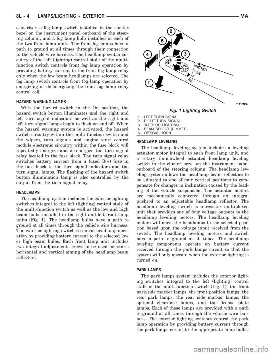
HEADLAMPS
The headlamp system includes the exterior lighting
switches integral to the left (lighting) control stalk of
the multi-function switch as well as the low and high
beam bulbs installed in the right and left front lamp
units (Fig. 1). The headlamp bulbs have a path to
ground at all times through the vehicle wire harness.
The exterior lighting switches control headlamp oper-
ation by providing battery current to the selected low
or high beam bulbs. Each front lamp unit includes
two integral adjustment screws to be used for static
horizontal and vertical aiming of the headlamp beam
reflectors.HEADLAMP LEVELING
The headlamp leveling system includes a leveling
actuator motor integral to each front lamp unit, and
a rotary thumbwheel actuated headlamp leveling
switch in the cluster bezel on the instrument panel
outboard of the steering column. The headlamp lev-
eling system allows the headlamp beam reflectors to
be adjusted to one of four vertical positions to com-
pensate for changes in inclination caused by the load-
ing of the vehicle suspension. The actuator motors
are mechanically connected through an integral
pushrod to an adjustable headlamp reflector. The
headlamp leveling switch is a resistor multiplexed
unit that provides one of four voltage outputs to the
headlamp leveling motors. The headlamp leveling
motors will move the headlamps to the selected posi-
tion based upon the voltage input received from the
switch. The headlamp leveling motors and switch
have a path to ground at all times. The headlamp
leveling components operate on battery current
received through the park lamps circuit so that the
system will only operate when the exterior lighting is
turned on.
PARK LAMPS
The park lamps system includes the exterior light-
ing switches integral to the left (lighting) control
stalk of the multi-function switch (Fig. 1), the front
park/side marker lamps, the front position lamps, the
rear park lamps, the rear side marker lamps, the
optional clearance lamps, and the license plate
lamps. Each of these lamps are provided with a path
to ground at all times through the vehicle wire har-
ness. The exterior lighting switches control the park
lamp operation by providing battery current through
the park lamps circuit to the appropriate lamp bulbs.
Fig. 1 Lighting Switch
1 - LEFT TURN SIGNAL
2 - RIGHT TURN SIGNAL
3 -EXTERIOR LIGHTING
4 - BEAM SELECT (DIMMER)
5 - OPTICAL HORN
8L - 4 LAMPS/LIGHTING - EXTERIORVA