Page 1672 of 2305
Fig. 5 05 FRAME DIMENSIONS 1
VAFRAME & BUMPERS 13 - 5
Page 1673 of 2305
Fig. 6 05 FRAME DIMENSIONS 2
13 - 6 FRAME & BUMPERSVA
Page 1674 of 2305
Fig. 7 FRAME DIMENSIONS
VAFRAME & BUMPERS 13 - 7
Page 2034 of 2305
BODY STRUCTURE
TABLE OF CONTENTS
page page
GAP AND FLUSH
SPECIFICATIONS.......................91OPENING DIMENSIONS
SPECIFICATIONS.......................93
GAP AND FLUSH
SPECIFICATIONS
GAP & FLUSH DIMENSIONS INDEX
DESCRIPTION FIGURE
FRONT DOORS 1
SLIDING DOORS 2
REAR DOORS 3
NOTE:
All measurements are in mm.
LOCATION GAP FLUSH
1 Door at top. 7
0.5FLUSH
2 Door at upper b-pil-
lar.7
0.5Up to max 1
mm recessed,
at rear with 1
mm overlap
(wind noise)
3 Door at bottom. 8
0.5FLUSH
4 Door at wheelhouse. 7
0.5FLUSH
5 Door ridge at wheel-
house and b-pillar.Ð FLUSH
6 Door at a-pillar. 8
0.5FLUSH
Fig. 1 FRONT DOOR
VABODY STRUCTURE 23 - 91
Page 2036 of 2305
OPENING DIMENSIONS
SPECIFICATIONS
BODY OPENING DIMENSIONS INDEX
DESCRIPTION FIGURE
WINDSHIELD OPENING 4
Fig. 4 WINDSHIELD OPENING
VABODY STRUCTURE 23 - 93
Page 2061 of 2305

CONTROLS - REAR
TABLE OF CONTENTS
page page
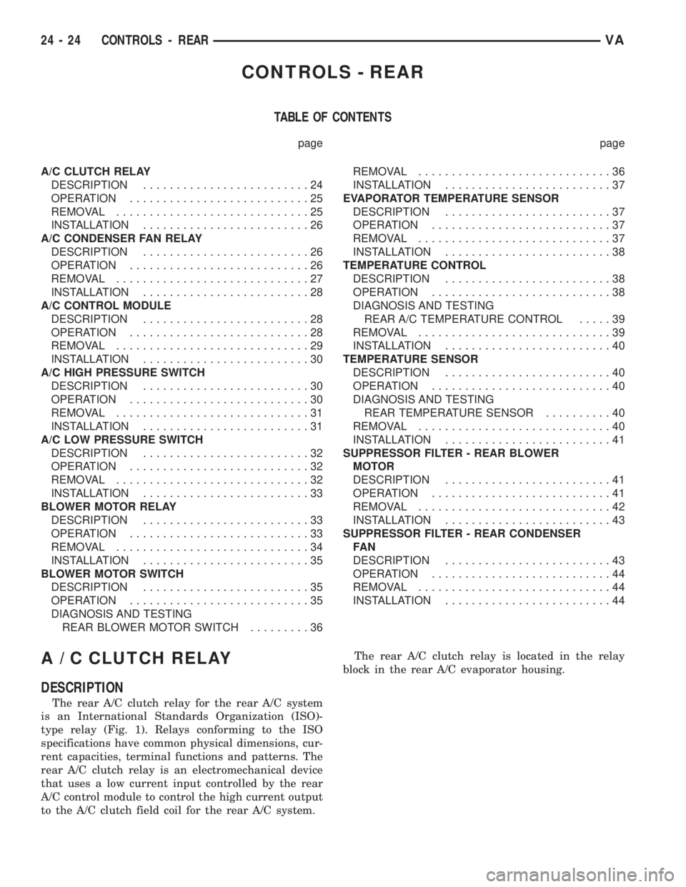
A/C CLUTCH RELAY
DESCRIPTION.........................24
OPERATION...........................25
REMOVAL.............................25
INSTALLATION.........................26
A/C CONDENSER FAN RELAY
DESCRIPTION.........................26
OPERATION...........................26
REMOVAL.............................27
INSTALLATION.........................28
A/C CONTROL MODULE
DESCRIPTION.........................28
OPERATION...........................28
REMOVAL.............................29
INSTALLATION.........................30
A/C HIGH PRESSURE SWITCH
DESCRIPTION.........................30
OPERATION...........................30
REMOVAL.............................31
INSTALLATION.........................31
A/C LOW PRESSURE SWITCH
DESCRIPTION.........................32
OPERATION...........................32
REMOVAL.............................32
INSTALLATION.........................33
BLOWER MOTOR RELAY
DESCRIPTION.........................33
OPERATION...........................33
REMOVAL.............................34
INSTALLATION.........................35
BLOWER MOTOR SWITCH
DESCRIPTION.........................35
OPERATION...........................35
DIAGNOSIS AND TESTING
REAR BLOWER MOTOR SWITCH.........36REMOVAL.............................36
INSTALLATION.........................37
EVAPORATOR TEMPERATURE SENSOR
DESCRIPTION.........................37
OPERATION...........................37
REMOVAL.............................37
INSTALLATION.........................38
TEMPERATURE CONTROL
DESCRIPTION.........................38
OPERATION...........................38
DIAGNOSIS AND TESTING
REAR A/C TEMPERATURE CONTROL.....39
REMOVAL.............................39
INSTALLATION.........................40
TEMPERATURE SENSOR
DESCRIPTION.........................40
OPERATION...........................40
DIAGNOSIS AND TESTING
REAR TEMPERATURE SENSOR..........40
REMOVAL.............................40
INSTALLATION.........................41
SUPPRESSOR FILTER - REAR BLOWER
MOTOR
DESCRIPTION.........................41
OPERATION...........................41
REMOVAL.............................42
INSTALLATION.........................43
SUPPRESSOR FILTER - REAR CONDENSER
FA N
DESCRIPTION.........................43
OPERATION...........................44
REMOVAL.............................44
INSTALLATION.........................44
A / C CLUTCH RELAY
DESCRIPTION
The rear A/C clutch relay for the rear A/C system
is an International Standards Organization (ISO)-
type relay (Fig. 1). Relays conforming to the ISO
specifications have common physical dimensions, cur-
rent capacities, terminal functions and patterns. The
rear A/C clutch relay is an electromechanical device
that uses a low current input controlled by the rear
A/C control module to control the high current output
to the A/C clutch field coil for the rear A/C system.The rear A/C clutch relay is located in the relay
block in the rear A/C evaporator housing.
24 - 24 CONTROLS - REARVA
Page 2063 of 2305

INSTALLATION
(1) Position the rear A/C clutch relay into the
proper receptacle of the relay block located in the
rear A/C evaporator housing.
(2) Align the A/C clutch relay terminals with the
terminal cavities in the relay block receptacle and
push down firmly on the relay until the terminals
are fully seated.
(3) Install the rear air filter (Refer to 24 - HEAT-
ING & AIR CONDITIONING/DISTRIBUTION -
REAR/AIR FILTER - INSTALLATION).
(4) Reconnect the negative battery cable.
A / C CONDENSER FAN RELAY
DESCRIPTION
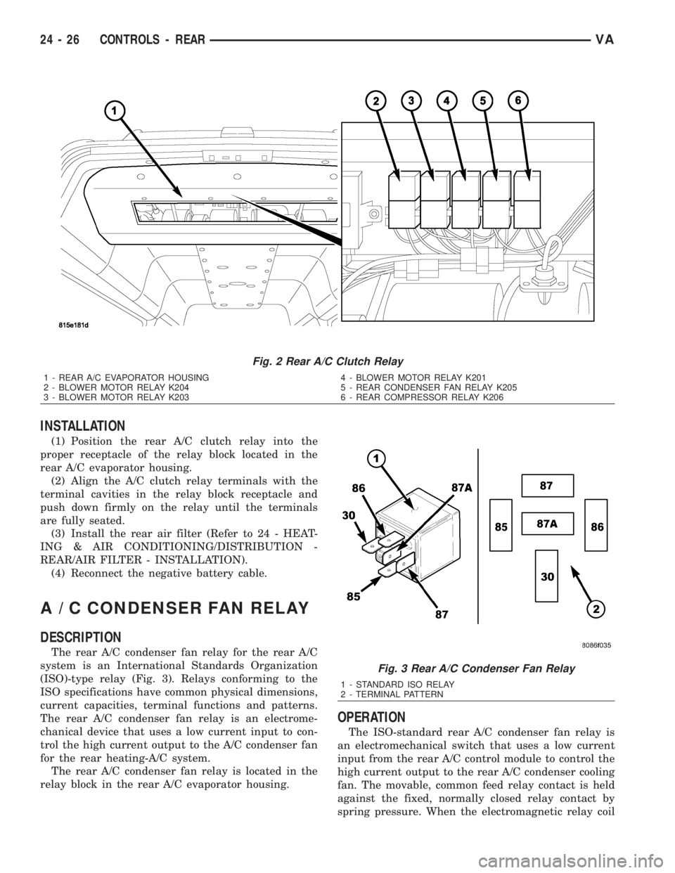
The rear A/C condenser fan relay for the rear A/C
system is an International Standards Organization
(ISO)-type relay (Fig. 3). Relays conforming to the
ISO specifications have common physical dimensions,
current capacities, terminal functions and patterns.
The rear A/C condenser fan relay is an electrome-
chanical device that uses a low current input to con-
trol the high current output to the A/C condenser fan
for the rear heating-A/C system.
The rear A/C condenser fan relay is located in the
relay block in the rear A/C evaporator housing.
OPERATION
The ISO-standard rear A/C condenser fan relay is
an electromechanical switch that uses a low current
input from the rear A/C control module to control the
high current output to the rear A/C condenser cooling
fan. The movable, common feed relay contact is held
against the fixed, normally closed relay contact by
spring pressure. When the electromagnetic relay coil
Fig. 2 Rear A/C Clutch Relay
1 - REAR A/C EVAPORATOR HOUSING
2 - BLOWER MOTOR RELAY K204
3 - BLOWER MOTOR RELAY K2034 - BLOWER MOTOR RELAY K201
5 - REAR CONDENSER FAN RELAY K205
6 - REAR COMPRESSOR RELAY K206
Fig. 3 Rear A/C Condenser Fan Relay
1 - STANDARD ISO RELAY
2 - TERMINAL PATTERN
24 - 26 CONTROLS - REARVA
Page 2070 of 2305

INSTALLATION
NOTE: Replacement of the PTFE thread sealing
tape is required anytime the rear A/C low pressure
switch is removed from the rear suction line line.
Failure to replace the sealing tape could result in a
rear refrigerant system leak.
(1) Remove the tape or plug from the rear suction
line fitting.
(2) Install PTFE thread sealing tape onto the rear
A/C low pressure switch and install the switch onto
the rear suction line. Tightened the A/C low pressure
switch to 10 N´m (88 in. lbs.).
(3) Connect the wiring harness connector to the
rear A/C low pressure switch.
(4) Install new insulating tape around the rear A/C
low pressure switch area.
(5) Reconnect the negative battery cable.
(6) Evacuate the rear refrigerant system (Refer to
24 - HEATING & AIR CONDITIONING/PLUMBING
- STANDARD PROCEDURE - REFRIGERANT SYS-
TEM EVACUATE).
(7) Charge the rear refrigerant system (Refer to 24
- HEATING & AIR CONDITIONING/PLUMBING -
STANDARD PROCEDURE - REFRIGERANT SYS-
TEM CHARGE).
(8) Install the cover onto the rear A/C evaporator
housing (Refer to 24 - HEATING & AIR CONDI-
TIONING/DISTRIBUTION - REAR/A/C EVAPORA-
TOR COVER-REAR - INSTALLATION).
BLOWER MOTOR RELAY
DESCRIPTION
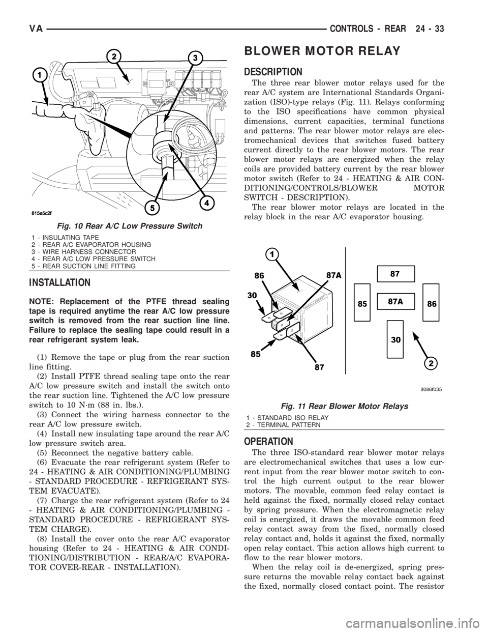
The three rear blower motor relays used for the
rear A/C system are International Standards Organi-
zation (ISO)-type relays (Fig. 11). Relays conforming
to the ISO specifications have common physical
dimensions, current capacities, terminal functions
and patterns. The rear blower motor relays are elec-
tromechanical devices that switches fused battery
current directly to the rear blower motors. The rear
blower motor relays are energized when the relay
coils are provided battery current by the rear blower
motor switch (Refer to 24 - HEATING & AIR CON-
DITIONING/CONTROLS/BLOWER MOTOR
SWITCH - DESCRIPTION).
The rear blower motor relays are located in the
relay block in the rear A/C evaporator housing.
OPERATION
The three ISO-standard rear blower motor relays
are electromechanical switches that uses a low cur-
rent input from the rear blower motor switch to con-
trol the high current output to the rear blower
motors. The movable, common feed relay contact is
held against the fixed, normally closed relay contact
by spring pressure. When the electromagnetic relay
coil is energized, it draws the movable common feed
relay contact away from the fixed, normally closed
relay contact and, holds it against the fixed, normally
open relay contact. This action allows high current to
flow to the rear blower motors.
When the relay coil is de-energized, spring pres-
sure returns the movable relay contact back against
the fixed, normally closed contact point. The resistor
Fig. 10 Rear A/C Low Pressure Switch
1 - INSULATING TAPE
2 - REAR A/C EVAPORATOR HOUSING
3 - WIRE HARNESS CONNECTOR
4 - REAR A/C LOW PRESSURE SWITCH
5 - REAR SUCTION LINE FITTING
Fig. 11 Rear Blower Motor Relays
1 - STANDARD ISO RELAY
2 - TERMINAL PATTERN
VACONTROLS - REAR 24 - 33