2006 MERCEDES-BENZ SPRINTER check transmission fluid
[x] Cancel search: check transmission fluidPage 838 of 2305

Operate tester pump to apply 103.4 kPa (15 psi)
pressure to system. If hoses enlarge excessively or
bulges while testing, replace as necessary. Observe
gauge pointer and determine condition of cooling sys-
tem according to following criteria:
Holds Steady:If pointer remains steady for two
minutes, serious coolant leaks are not present in sys-
tem. However, there could be an internal leak that
does not appear with normal system test pressure. If
it is certain that coolant is being lost and leaks can-
not be detected, inspect for interior leakage or per-
form Internal Leakage Test.
Drops Slowly:Indicates a small leak or seepage
is occurring. Examine all connections for seepage or
slight leakage with a flashlight. Inspect radiator,
hoses, gasket edges and heater. Seal small leak holes
with a Sealer Lubricant (or equivalent). Repair leak
holes and inspect system again with pressure
applied.
Drops Quickly:Indicates that serious leakage is
occurring. Examine system for external leakage. If
leaks are not visible, inspect for internal leakage.
Large radiator leak holes should be repaired by a
reputable radiator repair shop.
INTERNAL LEAKAGE INSPECTION
Remove engine oil pan drain plug and drain a
small amount of engine oil. If coolant is present in
the pan, it will drain first because it is heavier than
oil. An alternative method is to operate engine for a
short period to churn the oil. After this is done,
remove engine dipstick and inspect for water glob-ules. Also inspect transmission dipstick for water
globules and transmission fluid cooler for leakage.
WARNING: WITH RADIATOR PRESSURE TESTER
TOOL INSTALLED ON RADIATOR, DO NOT ALLOW
PRESSURE TO EXCEED 110 KPA (20 PSI). PRES-
SURE WILL BUILD UP QUICKLY IF A COMBUSTION
LEAK IS PRESENT. TO RELEASE PRESSURE,
ROCK TESTER FROM SIDE TO SIDE. WHEN
REMOVING TESTER, DO NOT TURN TESTER MORE
THAN 1/2 TURN IF SYSTEM IS UNDER PRESSURE.
Operate engine without pressure cap on coolant
container until thermostat opens. Attach a Pressure
Tester to container. If pressure builds up quickly it
indicates a combustion leak exists. This is usually
the result of a cylinder head gasket leak or crack in
engine. Repair as necessary.
If there is not an immediate pressure increase,
pump the Pressure Tester. Do this until indicated
pressure is within system range of 110 kPa (16 psi).
Fluctuation of gauge pointer indicates compression or
combustion leakage into cooling system.
Because the vehicle is equipped with a catalytic
converter,do notremove spark plug cables or short
out cylinders to isolate compression leak.
If the needle on dial of pressure tester does not
fluctuate, race engine a few times to check for an
abnormal amount of coolant or steam. This would be
emitting from exhaust pipe. Coolant or steam from
exhaust pipe may indicate a faulty cylinder head gas-
ket, cracked engine cylinder block or cylinder head.
A convenient check for exhaust gas leakage into
cooling system is provided by a commercially avail-
able Block Leak Check tool. Follow manufacturers
instructions when using this product.
COMBUSTION LEAKAGE TEST - WITHOUT PRES-
SURE TESTER
DO NOT WASTE reusable coolant. If solution is
clean, drain coolant into a clean and suitably marked
container for reuse.
WARNING: Do not remove cylinder block drain
plugs or loosen radiator drain with system hot and
under pressure. serious burns from coolant can
occur.
Drain sufficient coolant to allow thermostat
removal.
Remove accessory drive belt.
Add coolant to pressure container to bring level to
within 6.3 mm (1/4 in) of top of thermostat housing.
CAUTION: Avoid overheating. Do not operate
engine for an excessive period of time. Open drain-
cock immediately after test to eliminate boil over.
Fig. 2 PRESSURE TESTING
1 - PRESSURE RESERVOIR CAP
2 - PRESSURE RESERVOIR
3 - PRESSURE TESTER
VAENGINE 7 - 11
Page 862 of 2305

²Position of selector lever.
²Selected shift range.
²CAN signals.
²Engine Status.
Engine speed limits may be reached in all gears
with full throttle or in kick-down operation. In for-
ward driving, the shift range of the forward gears
can be adjusted by the operator by tipping the selec-
tor lever to the left or right (AutoStick). However, the
TCM features a downshift inhibitor to prevent the
engine from overspeeding.
OPERATION
The transmission control module (TCM) deter-
mines the current operating conditions of the vehicle
and controls the shifting process for shift comfort and
driving situations. It receives this operating data
from sensors and broadcast messages from other
modules.
The TCM uses inputs from several sensors that are
directly hardwired to the controller and it uses sev-
eral indirect inputs that are used to control shifts.
This information is used to actuate the proper sole-
noids in the valve body to achieve the desired gear.
The shift lever assembly (SLA) has several items
that are monitored by the TCM to calculate shift
lever position. The reverse light switch, an integral
part of the SLA, controls the reverse light relay con-
trol circuit. The Brake/Transmission Shift Interlock
(BTSI) solenoid and the park lockout solenoid (also
part of the SLA) are controlled by the TCM.
The ECM and ABS broadcast messages over the
controller area network (CAN C) bus for use by the
TCM. The TCM uses this information, with other
inputs, to determine the transmission operating con-
ditions.
The TCM:
²determines the momentary operating conditions
of the vehicle.
²controls all shift processes.
²considers shift comfort and the driving situation.
The TCM controls the solenoid valves for modulat-
ing shift pressures and gear changes. Relative to the
torque being transmitted, the required pressures are
calculated from load conditions, engine rpm, vehicle
speed, and ATF temperature.
The following functions are contained in the TCM:
²Shift Program
²Downshift Safety
²Torque Converter Lock-Up Clutch.
²Adaptation.
This transmission does not have a TCM relay.
Power is supplied to the SLA and the TCM directly
from the ignition.
The TCM continuously checks for electrical prob-
lems, mechanical problems, and some hydraulic prob-
lems. When a problem is sensed, the TCM stores a
diagnostic trouble code (DTC). Some of these codescause the transmission to go into ªLimp-Inº or
ªdefaultº mode. Some DTCs cause permanent
Limp-In and others cause temporary Limp-In. The
NAG1 defaults in the current gear position if a DTC
is detected, then after a key cycle the transmission
will go into Limp-in, which is mechanical 2nd gear.
Some DTCs may allow the transmission to resume
normal operation (recover) if the detected problem
goes away. A permanent Limp-In DTC will recover
when the key is cycled, but if the same DTC is
detected for three key cycles the system will not
recover and the DTC must be cleared from the TCM
with the DRBIIItscan tool.
TCM SIGNALS
The TCM registers one part of the input signals by
direct inputs, the other part by CAN C bus. In addi-
tion to the direct control of the actuators, the TCM
sends various output signals by CAN C bus to other
control modules.
Selector Lever Position
The TCM monitors the SLA for all shift lever posi-
tions via the CAN bus.
ATF Temperature Sensor
The ATF temperature sensor is a positive temper-
ature co-efficient (PTC) thermistor. It measures the
temperature of the transmission fluid and is a direct
input signal for the TCM. The temperature of the
ATF has an influence on the shifttime and resulting
shift quality. As the temperature rises, resistance
rises, and therefore, the probing voltage is decreas-
ing. Because of its registration, the shifting process
can be optimized in all temperature ranges.
The ATF temperature sensor is wired in series
with the park/neutral contact. The temperature sig-
nal is transmitted to the TCM only when the reed
contact of the park/neutral contact is closed because
the TCM only reads ATF temperature while in any
forward gear, or REVERSE. When the transmission
is in PARK or NEUTRAL, the TCM will substitute
the engine temperature for the ATF temperature.
Starter Interlock
The TCM monitors a contact switch wired in series
with the transmission temperature sensor to deter-
mine PARK and NEUTRAL positions. The contact
switch is open in PARK and NEUTRAL. The TCM
senses transmission temperature as high (switch
supply voltage), confirming switch status as open.
The TCM then broadcasts a message over CAN bus
to confirm switch status. The PCM receives this
information and allows operation of the starter cir-
cuit.
VAELECTRONIC CONTROL MODULES 8E - 7
Page 1585 of 2305
(11) Install the torque converter access plate. Refer
to (Refer to 21 - TRANSMISSION/TRANSAXLE/AU-
TOMATIC - NAG1 - INSTALLATION) for correct
sequence and torque specification.
(12) Install the transmission cooler lines to trans-
mission. (Refer to 21 - TRANSMISSION/TRANS-
AXLE/AUTOMATIC - NAG1 - INSTALLATION) for
correct sequence and torque specification.
(13) Connect the engine valley drain hose to the
transmission (Fig. 5).
(14) Install transmission electrical connector and
shifter hardware. Refer to (Refer to 21 - TRANSMIS-
SION/TRANSAXLE/AUTOMATIC - NAG1 - INSTAL-
LATION) for correct sequence and torque
specification.
(15) Install the steering gear and tighten in two
stages. 25 N´m (18.5 lbs. ft.), then 45 N´m (33 lbs. ft.)
plus 90É.
(16) Install the starter.
(17) Connect the ground strap (left side).
(18) Align and install the exhaust and bracket
(Refer to 11 - EXHAUST SYSTEM/EXHAUST PIPE -
INSTALLATION).
(19) Lower the vehicle.
(20) Install the lower heater housing and filter.
(21) Install the air inlet hose, CCV breather and
CCV heater at the turbocharger (Fig. 4).
(22) Connect the coolant supply and return hoses.
(23) Connect the brake booster vacuum hose at the
vacuum pump.(24) Connect the fuel lines at the filter assembly
(Fig. 9).
(25) Connect the power steering hoses.
(26) Install the radiator/charge air cooler and
hose(s) assemblies (Refer to 7 - COOLING/ENGINE/
RADIATOR - INSTALLATION).
(27) Install A/C condenser and fan assemblies Con-
nect the fan harness connector.
(28) Connect the refrigerant lines.
(29) Install a air conditioning receiver/drier (Refer
to 24 - HEATING & AIR CONDITIONING/PLUMB-
ING/RECEIVER / DRIER - INSTALLATION).
(30) Connect the upper and lower radiator hoses.
(31) Connect the transmission lines at the radia-
tor.
(32) Install air cleaner housing and connect the air
inlet duct and air flow sensor.
(33) Connect the charge air cooler hose at intake
manifold. (Refer to 9 - ENGINE/AIR INTAKE SYS-
TEM/AIR CLEANER HOUSING - INSTALLATION).
(34) Route the engine wiring harness inside the
vehicle and connect.
(35) Install the turbocharger heat shield.
(36) Install the front grille and fascia assembly.
(37) Connect the negative battery cable.
(38) Check and fill engine oil (Refer to LUBRICA-
TION & MAINTENANCE/FLUID TYPES - SPECIFI-
CATIONS).
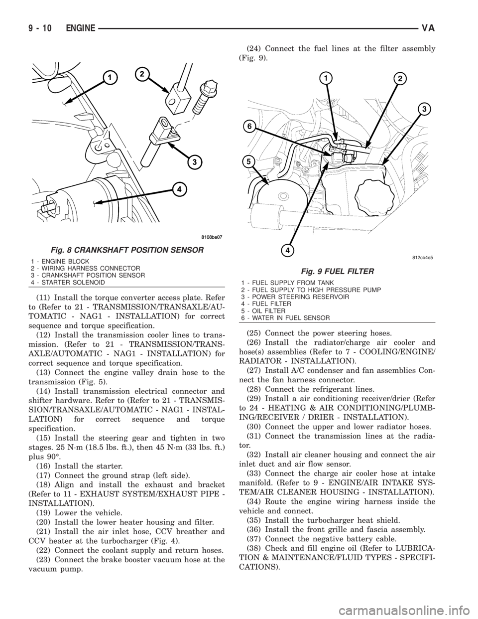
Fig. 8 CRANKSHAFT POSITION SENSOR
1 - ENGINE BLOCK
2 - WIRING HARNESS CONNECTOR
3 - CRANKSHAFT POSITION SENSOR
4 - STARTER SOLENOID
Fig. 9 FUEL FILTER
1 - FUEL SUPPLY FROM TANK
2 - FUEL SUPPLY TO HIGH PRESSURE PUMP
3 - POWER STEERING RESERVOIR
4 - FUEL FILTER
5 - OIL FILTER
6 - WATER IN FUEL SENSOR
9 - 10 ENGINEVA
Page 1740 of 2305
PUMP
TABLE OF CONTENTS
page page
PUMP
DESCRIPTION.........................11
OPERATION...........................11
DIAGNOSIS AND TESTING - PUMP LEAKAGE . 11
STANDARD PROCEDURE
STANDARD PROCEDURE - POWER
STEERING PUMP - INITIAL OPERATION....11
STANDARD PROCEDURE - FLUSHING
POWER STEERING SYSTEM............12
REMOVAL.............................12
INSTALLATION.........................12
SPECIFICATIONS - TORQUE CHART........13
FLUID
STANDARD PROCEDURE
POWER STEERING PUMP FILL AND BLEED
PROCEDURE........................13FLUID COOLER TUBE
REMOVAL.............................13
INSTALLATION.........................13
HOSES
REMOVAL
REMOVAL - PRESSURE HOSE...........14
REMOVAL - RETURN LINE FROM PUMP TO
COOLER TUBE.......................14
REMOVAL - RETURN HOSE FROM GEAR
TO COOLER TUBE....................14
INSTALLATION
INSTALLATION - PRESSURE HOSE.......14
INSTALLATION - RETURN LINE FROM
PUMP TO COOLER TUBE...............14
INSTALLATION - RETURN HOSE FROM
GEAR TO COOLER TUBE...............14
PUMP
DESCRIPTION
CAUTION: Use approved fluid only in the power
steering system (Refer to LUBRICATION & MAINTE-
NANCE/FLUID TYPES - DESCRIPTION). No other
power steering or automatic transmission fluid is to
be used in the system. Damage may result to the
power steering pump and system if any other fluid
is used, and do not overfill.
The pump is connected to the steering gear via the
pressure hose and the return hose. The pump shaft
has a pressed-on pulley that is belt driven by the
crankshaft pulley.
All vehicles are equipped with a power steering
fluid cooler.
NOTE: Power steering pumps are not interchange-
able with pumps installed on other vehicles.
OPERATION
Hydraulic pressure is provided for the power steer-
ing gear by the belt driven power steering pump. The
power steering pumps are constant flow rate and dis-
placement, vane-type pumps.
DIAGNOSIS AND TESTING - PUMP LEAKAGE
The pump is serviced as an assembly and should
not be disassembled. The plastic pump reservoir and
the reservoir o-rings can be replaced.Check for leaks in the following areas:
²Pump shaft seal behind the pulley
²Pump to reservoir O-ring
²Reservoir cap
²Pressure and return lines
²Flow control valve fitting
STANDARD PROCEDURE
STANDARD PROCEDURE - POWER STEERING
PUMP - INITIAL OPERATION
WARNING: THE FLUID LEVEL SHOULD BE
CHECKED WITH ENGINE OFF TO PREVENT INJURY
FROM MOVING COMPONENTS.
CAUTION: Use approved fluid only in the power
steering system (Refer to LUBRICATION & MAINTE-
NANCE/FLUID TYPES - DESCRIPTION). No other
power steering or automatic transmission fluid is to
be used in the system. Damage may result to the
power steering pump and system if any other fluid
is used, and do not overfill.
Wipe filler cap clean, then check the fluid level.
The dipstick should indicateCOLDwhen the fluid is
at normal temperature.
(1) Turn steering wheel all the way to the left
(2) Fill the pump fluid reservoir to the proper level
and let the fluid settle for at least two (2) minutes.
(3) Raise the front wheels off the ground.
VAPUMP 19 - 11
Page 1744 of 2305
TRANSMISSION
TABLE OF CONTENTS
page
AUTOMATIC TRANSMISSION NAG1 - SERVICE
INFORMATION............................1
AUTOMATIC TRANSMISSION NAG1 - SERVICE
INFORMATION
TABLE OF CONTENTS
page page
AUTOMATIC TRANSMISSION NAG1 - SERVICE
INFORMATION
DESCRIPTION..........................3
OPERATION............................4
DIAGNOSIS AND TESTING
AUTOMATIC TRANSMISSION............39
PRELIMINARY........................39
ROAD TESTING......................39
AUTOMATIC TRANSMISSION............40
STANDARD PROCEDURE - ALUMINUM
THREAD REPAIR......................42
REMOVAL.............................42
DISASSEMBLY.........................46
ASSEMBLY............................52
INSTALLATION.........................60
SCHEMATICS AND DIAGRAMS............65
SPECIFICATIONS - NAG1 AUTOMATIC
TRANSMISSION......................86
SPECIAL TOOLS - AUTOMATIC
TRANSMISSION - NAG1................87
INPUT CLUTCHES
DESCRIPTION.........................90
OPERATION...........................91
INPUT CLUTCH K1
DISASSEMBLY.........................92
ASSEMBLY............................94
INPUT CLUTCH K2
DISASSEMBLY.........................97
ASSEMBLY............................99
INPUT CLUTCH K3
DISASSEMBLY........................102
ASSEMBLY...........................103
ELECTROHYDRAULIC UNIT
DESCRIPTION........................105
OPERATION..........................112
REMOVAL............................120
DISASSEMBLY........................121
ASSEMBLY...........................125INSTALLATION........................129
FLUID AND FILTER
DESCRIPTION........................131
OPERATION..........................131
DIAGNOSIS AND TESTING
EFFECTS OF INCORRECT FLUID LEVEL . . 131
CAUSES OF BURNT FLUID.............132
FLUID CONTAMINATION...............132
STANDARD PROCEDURE
CHECK OIL LEVEL...................132
TRANSMISSION FILL.................133
FLUID/FILTER SERVICE...............134
FREEWHEELING CLUTCH
DESCRIPTION........................135
OPERATION..........................135
DISASSEMBLY........................136
ASSEMBLY...........................138
GEARSHIFT CABLE
DIAGNOSIS AND TESTING
GEARSHIFT CABLE..................138
REMOVAL............................139
INSTALLATION........................140
HOLDING CLUTCHES
DESCRIPTION........................141
OPERATION..........................142
HOLDING CLUTCH B1
DISASSEMBLY........................143
ASSEMBLY...........................145
HOLDING CLUTCH B2
DISASSEMBLY........................148
ASSEMBLY...........................150
INPUT SPEED SENSORS
DESCRIPTION........................153
OPERATION..........................154
OIL PUMP
DESCRIPTION........................154
OPERATION..........................154
DISASSEMBLY........................155
VATRANSMISSION 21 - 1
Page 1782 of 2305
DIAGNOSIS AND TESTING
AUTOMATIC TRANSMISSION
CAUTION: Before attempting any repair on a NAG1
automatic transmission, check for Diagnostic Trou-
ble Codes with the appropriate scan tool.
Transmission malfunctions may be caused by these
general conditions:
²Poor engine performance.
²Improper adjustments.
²Hydraulic malfunctions.
²Mechanical malfunctions.
²Electronic malfunctions.
²Transfer case performance (if equipped).
Diagnosis of these problems should always begin
by checking the easily accessible variables: fluid level
and condition, gearshift cable adjustment. Then per-
form a road test to determine if the problem has been
corrected or if more diagnosis is necessary.
PRELIMINARY
Two basic procedures are required. One procedure
for vehicles that are drivable and an alternate proce-
dure for disabled vehicles (will not back up or move
forward).
VEHICLE IS DRIVABLE
(1) Check for transmission fault codes using the
appropriate scan tool.
(2) Check fluid level and condition.
(3) Adjust gearshift cable if complaint was based
on delayed, erratic, or harsh shifts.
(4) Road test and note how transmission upshifts,
downshifts, and engages.
VEHICLE IS DISABLED
(1) Check fluid level and condition.(2) Check for broken or disconnected gearshift
cable.
(3) Check for cracked, leaking cooler lines, or loose
or missing pressure-port plugs.
(4) Raise and support vehicle on safety stands,
start engine, shift transmission into gear, and note
following:
(a) If propeller shaft turns but wheels do not,
problem is with differential or axle shafts.
(b) If propeller shaft does not turn and transmis-
sion is noisy, stop engine. Remove oil pan, and
check for debris. If pan is clear, remove transmis-
sion and check for damaged driveplate, converter,
oil pump, or input shaft.
(c) If propeller shaft does not turn and transmis-
sion is not noisy, perform hydraulic-pressure test to
determine if problem is hydraulic or mechanical.
ROAD TESTING
Before road testing, be sure the fluid level and con-
trol cable adjustments have been checked and
adjusted if necessary. Verify that all diagnostic trou-
ble codes have been resolved.
Observe engine performance during the road test.
A poorly tuned engine will not allow accurate analy-
sis of transmission operation.
Operate the transmission in all gear ranges. Check
for shift variations and engine flare which indicates
slippage. Note if shifts are harsh, spongy, delayed,
early, or if part throttle downshifts are sensitive.
Slippage indicated by engine flare, usually means
clutch, overrunning clutch, or line pressure problems.
A slipping clutch can often be determined by com-
paring which internal units are applied in the vari-
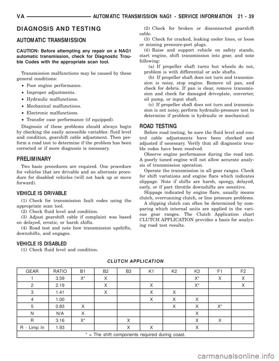
ous gear ranges. The Clutch Application chart
CLUTCH APPLICATION provides a basis for analyz-
ing road test results.
CLUTCH APPLICATION
GEAR RATIO B1 B2 B3 K1 K2 K3 F1 F2
1 3.59 X* X X* X X
2 2.19 X X X* X
3 1.41 X X X
4 1.00 X X X
5 0.83 X X X X*
N N/A X X
R 3.16 X* X X X
R - Limp In 1.93 X X X
* = The shift components required during coast.
VAAUTOMATIC TRANSMISSION NAG1 - SERVICE INFORMATION 21 - 39
Page 1796 of 2305
NOTE: During the measurement the snap ring (7)
(Fig. 49) must contact the upper bearing surface of
the groove in the outer multiple-disc carrier (8).
NOTE: Pay attention to sequence of discs. If the
original clutch discs are reused, be sure to return
the disc identified on disassembly as belonging on
top of the spring washer (4) to its original location.
Place new friction multiple-discs in ATF fluid for
one hour before installing.
(4) Insert and measure spring washer (4) (Fig. 49)
and multiple-disc pack B3 (2, 6).
(a) Put multiple-discs for multiple-disc holding
clutch B3 together in the sequence shown in the
illustration and insert individually.
(b)
CAUTION: Apply only light pressure (less than 10 N
(3 lbs.) of force) to the clutch pack when measuring
the clutch clearance with the feeler gauge. Applying
excessive force to the clutch will give an incorrect
reading and lead to a transmission failure.Using a
feeler gauge, determine the play ªLº at three points
between the snap ring (7) and outer multiple-disc
(1). B3 clutch clearance should be 1.0-1.4 mm
(0.039-0.055 in.). Adjust the clearance as necessary.
(c) Adjust with snap-ring (7), if necessary. Snap-
rings are available in thicknesses of 3.2 mm (0.126
in.), 3.5 mm (0.138 in.), 3.8 mm (0.150 in.), 4.1 mm
(0.162 in.), 4.4 mm (0.173 in.), and 4.7 mm (0.185
in.).
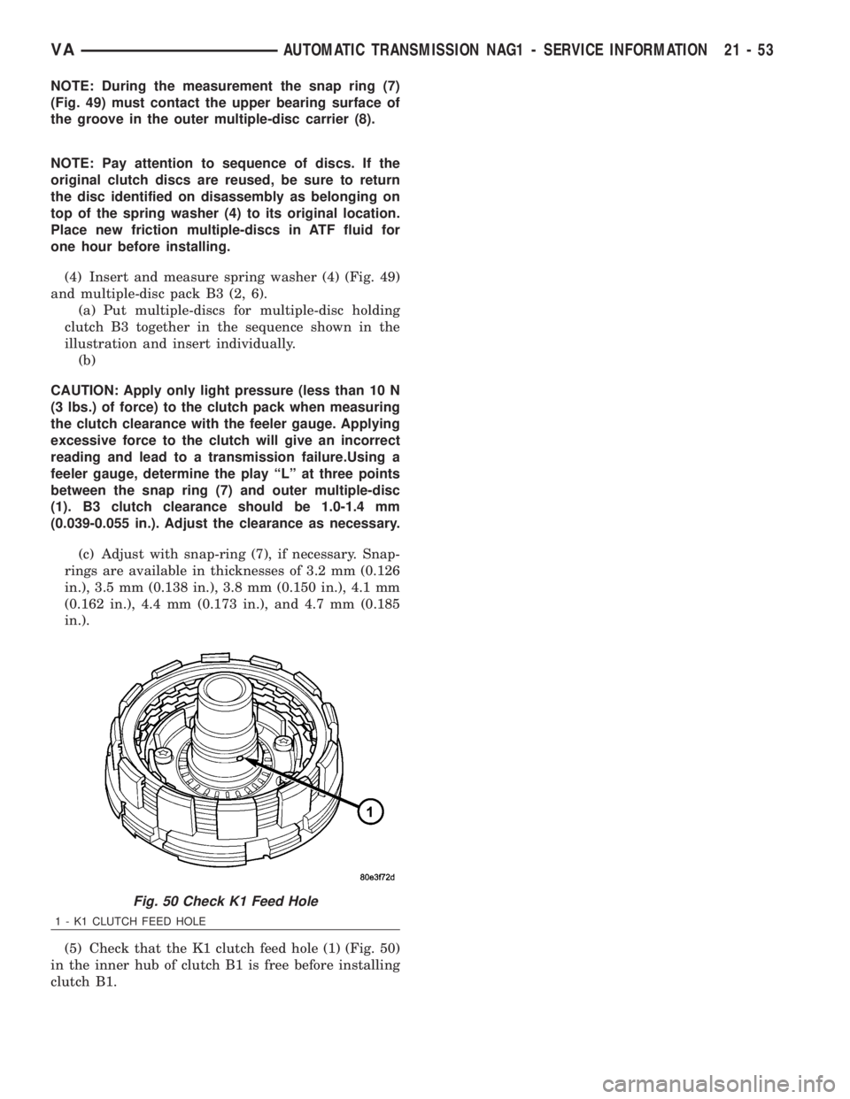
(5) Check that the K1 clutch feed hole (1) (Fig. 50)
in the inner hub of clutch B1 is free before installing
clutch B1.
Fig. 50 Check K1 Feed Hole
1 - K1 CLUTCH FEED HOLE
VAAUTOMATIC TRANSMISSION NAG1 - SERVICE INFORMATION 21 - 53
Page 1838 of 2305
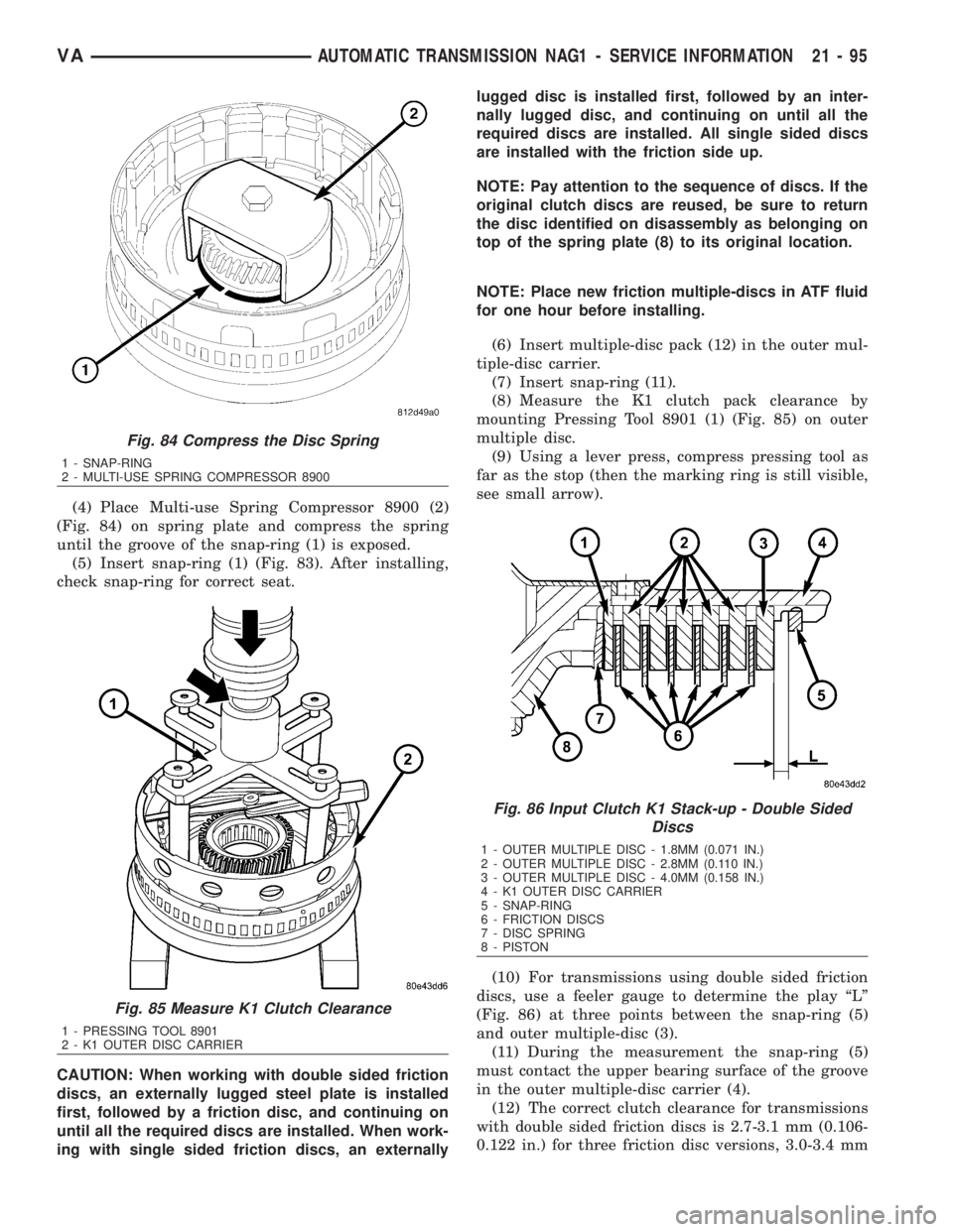
(4) Place Multi-use Spring Compressor 8900 (2)
(Fig. 84) on spring plate and compress the spring
until the groove of the snap-ring (1) is exposed.
(5) Insert snap-ring (1) (Fig. 83). After installing,
check snap-ring for correct seat.
CAUTION: When working with double sided friction
discs, an externally lugged steel plate is installed
first, followed by a friction disc, and continuing on
until all the required discs are installed. When work-
ing with single sided friction discs, an externallylugged disc is installed first, followed by an inter-
nally lugged disc, and continuing on until all the
required discs are installed. All single sided discs
are installed with the friction side up.
NOTE: Pay attention to the sequence of discs. If the
original clutch discs are reused, be sure to return
the disc identified on disassembly as belonging on
top of the spring plate (8) to its original location.
NOTE: Place new friction multiple-discs in ATF fluid
for one hour before installing.
(6) Insert multiple-disc pack (12) in the outer mul-
tiple-disc carrier.
(7) Insert snap-ring (11).
(8) Measure the K1 clutch pack clearance by
mounting Pressing Tool 8901 (1) (Fig. 85) on outer
multiple disc.
(9) Using a lever press, compress pressing tool as
far as the stop (then the marking ring is still visible,
see small arrow).
(10) For transmissions using double sided friction
discs, use a feeler gauge to determine the play ªLº
(Fig. 86) at three points between the snap-ring (5)
and outer multiple-disc (3).
(11) During the measurement the snap-ring (5)
must contact the upper bearing surface of the groove
in the outer multiple-disc carrier (4).
(12) The correct clutch clearance for transmissions
with double sided friction discs is 2.7-3.1 mm (0.106-
0.122 in.) for three friction disc versions, 3.0-3.4 mm
Fig. 84 Compress the Disc Spring
1 - SNAP-RING
2 - MULTI-USE SPRING COMPRESSOR 8900
Fig. 85 Measure K1 Clutch Clearance
1 - PRESSING TOOL 8901
2 - K1 OUTER DISC CARRIER
Fig. 86 Input Clutch K1 Stack-up - Double Sided
Discs
1 - OUTER MULTIPLE DISC - 1.8MM (0.071 IN.)
2 - OUTER MULTIPLE DISC - 2.8MM (0.110 IN.)
3 - OUTER MULTIPLE DISC - 4.0MM (0.158 IN.)
4 - K1 OUTER DISC CARRIER
5 - SNAP-RING
6 - FRICTION DISCS
7 - DISC SPRING
8 - PISTON
VAAUTOMATIC TRANSMISSION NAG1 - SERVICE INFORMATION 21 - 95