Page 2285 of 3383
![INFINITI QX56 2006 Factory Service Manual LAN-16
[CAN]
TROUBLE DIAGNOSES WORK FLOW
Revision: November 20092006 QX56
CAN Diagnostic Support MonitorUKS004SU
DESCRIPTION OF “CAN DIAG SUPPORT MNTR” SCREEN FOR ECM
Display Results (Present)
�OK](/manual-img/42/57028/w960_57028-2284.png "INFINITI QX56 2006 Factory Service Manual LAN-16
[CAN]
TROUBLE DIAGNOSES WORK FLOW
Revision: November 20092006 QX56
CAN Diagnostic Support MonitorUKS004SU
DESCRIPTION OF “CAN DIAG SUPPORT MNTR” SCREEN FOR ECM
Display Results (Present)
�OK")
LAN-16
[CAN]
TROUBLE DIAGNOSES WORK FLOW
Revision: November 20092006 QX56
CAN Diagnostic Support MonitorUKS004SU
DESCRIPTION OF “CAN DIAG SUPPORT MNTR” SCREEN FOR ECM
Display Results (Present)
�OK: Normal
�UNKWN: The diagnosed unit does not transmit or receive the applicable data normally.
�–: There is no received unit or the unit is not in the condition that reception diagnosis is performed.
Display Results (Past)
�OK: Normal
�0: There is malfunction now.
�1 ~ 39: Displays when it is normal at present and finds malfunction in the past. It increases like 0 →1→ 2...38→ 39 after returning to the
normal condition whenever IGN OFF →ON. If it is over 39, it is fixed to 39 until the self-diagnostic results are erased. It returns to 0
when malfunction is detected again in the process.
�– : Undiagnosed
PKIC3562E
“SELECT SYSTEM ”
screen “
CAN DIAG SUPPORT
MNTR ” screen Description
PresentPast
ENGINE TRANSMIT DIAG Make sure of normal transmission.
OK/UNKWN/–
OK/0/1~39/–
VDC/TCS/ABS
Make sure of normal reception from ABS
actuator and electric unit (control unit). OK/UNKWN/
–
METER/M&A Make sure of normal reception from combina-
tion meter. OK/UNKWN/
–
BCM/SEC Make sure of normal reception from BCM. OK/UNKWN/ –
ICC Make sure of normal reception from ICC unit. OK/UNKWN/ –
HVAC HVAC is not diagnosed. –
TCM Make sure of normal reception from TCM. OK/UNKWN/ –
EPS EPS is not diagnosed. –
IPDM E/R Make sure of normal reception from IPDM E/
R. OK/UNKWN/
–
e4WD e4WD is not diagnosed. –
AWD/4WD Make sure of normal reception from transfer
control unit. OK/UNKWN/
–
Page 2300 of 3383
CAN COMMUNICATIONLAN-31
[CAN]
C
DE
F
G H
I
J
L
M A
B
LAN
Revision: November 2009 2006 QX56
CAN Communication UnitUKS000NV
Go to CAN system, when selecting your CAN system type from the following table.
×: Applicable
NOTE:
Vehicles equipped with ICC can be identified by the presence of a ICC switch.
TYPE1/TYPE2
System diagram
�Ty pe 1
Body type Wagon
Axle 2WD 4WD
Engine VK56DE
Transmission A/T
Brake control VDC
ICC system ××
CAN system type 1234
CAN system trouble diagnosis LAN-39
LAN-57LAN-79LAN-98
BKIA0191E
PKIC2711E
Page 2301 of 3383
LAN-32
[CAN]
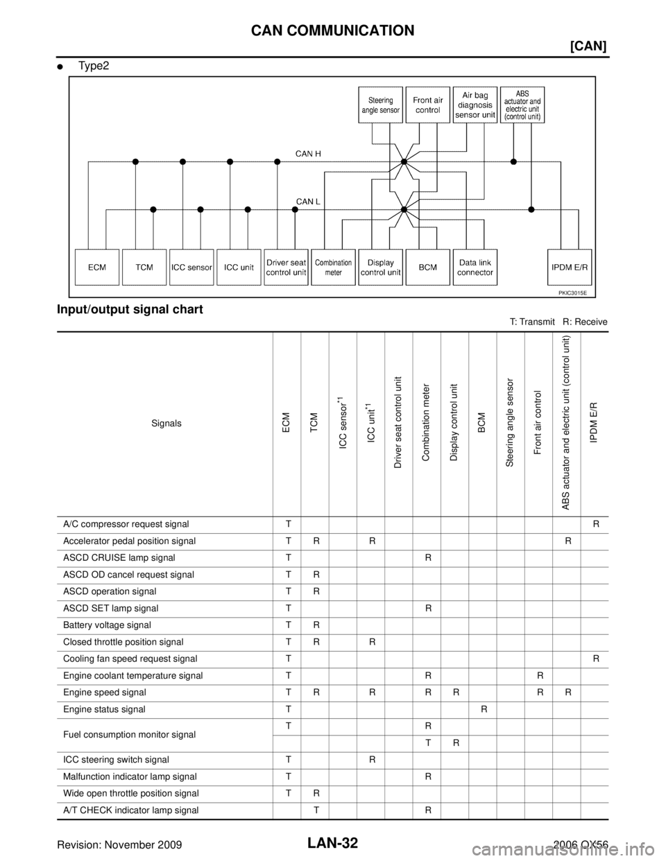
CAN COMMUNICATION
Revision: November 20092006 QX56
�Ty p e 2
Input/output signal chart
T: Transmit R: Receive
PKIC3015E
SignalsECM
TCM
ICC sensor
*1
ICC unit
*1
Driver seat control unit Combination meter
Display control unit BCM
Steering angle sensor Front air control
ABS actuator and electric unit (control unit) IPDM E/R
A/C compressor request signal T R
Accelerator pedal position signal T RR R
ASCD CRUISE lamp signal TR
ASCD OD cancel request signal T R
ASCD operation signal T R
ASCD SET lamp signal TR
Battery voltage signal T R
Closed throttle position signal T R R
Cooling fan speed request signal T R
Engine coolant temperature signal TRR
Engine speed signal T RRR R R R
Engine status signal TR
Fuel consumption monitor signal TR
TR
ICC steering switch signal TR
Malfunction indicator lamp signal TR
Wide open throttle position signal T R
A/T CHECK indicator lamp signal TR
Page 2305 of 3383
![INFINITI QX56 2006 Factory Service Manual LAN-36
[CAN]
CAN COMMUNICATION
Revision: November 20092006 QX56
ASCD CRUISE lamp signalTR
ASCD OD cancel request signal T R
ASCD operation signal T R
ASCD SET lamp signal TR
Battery voltage signal T R](/manual-img/42/57028/w960_57028-2304.png "INFINITI QX56 2006 Factory Service Manual LAN-36
[CAN]
CAN COMMUNICATION
Revision: November 20092006 QX56
ASCD CRUISE lamp signalTR
ASCD OD cancel request signal T R
ASCD operation signal T R
ASCD SET lamp signal TR
Battery voltage signal T R")
LAN-36
[CAN]
CAN COMMUNICATION
Revision: November 20092006 QX56
ASCD CRUISE lamp signalTR
ASCD OD cancel request signal T R
ASCD operation signal T R
ASCD SET lamp signal TR
Battery voltage signal T R
Closed throttle position signal T R R
Cooling fan speed request signal T R
Engine coolant temperature signal TRR
Engine speed signal T RRR R R R R
Engine status signal TR
Fuel consumption monitor signal TR
TR
ICC steering switch signal TR
Malfunction indicator lamp signal TR
Wide open throttle position signal T R
A/T CHECK indicator lamp signal TR
A/T fluid temperature sensor signal TR
A/T position indicator lamp signal TR R R
A/T self-diagnosis signal R T
Current gear position signal TR R
Output shaft revolution signal R TR R
P range signal TR R R
Turbine revolution signal R TR
ICC sensor signal T R
Buzzer output signal TR
RT
ICC OD cancel request signal R RT
ICC operation signal R RT
ICC system display signal TR
System setting signal TR
RT
1st position switch signal RT
4th position switch signal RT
Distance to empty signal T R
Signals
ECM
TCM
ICC sensor
*1
ICC unit
*1
Driver seat control unit Combination meter
Display control unit BCM
Steering angle sensor Front air control
Transfer control unit
ABS actuator and electric unit (control unit) IPDM E/R
Page 2412 of 3383
LT-5
C
DE
F
G H
I
J
L
M A
B
LT
Revision: November 2009 2006 QX56
HEADLAMP (FOR USA)PFP:26010
Component Parts and Harness Connector LocationEKS00B7S
System DescriptionEKS00B7T
Control")
HEADLAMP (FOR USA)LT-5
C
DE
F
G H
I
J
L
M A
B
LT
Revision: November 2009 2006 QX56
HEADLAMP (FOR USA)PFP:26010
Component Parts and Harness Connector LocationEKS00B7S
System DescriptionEKS00B7T
Control of the headlamp system operation is dependent upon the position of the combination switch (lighting
switch). When the lighting switch is placed in the 2ND position, the BCM (body control module) receives input
requesting the headlamps (and tail lamps) illuminate. This input is communicated to the IPDM E/R (intelligent
power distribution module engine room) across the CAN communication lines. The CPU (central processing
unit) of the IPDM E/R controls the headlamp high and headlamp low relay coils. When energized, these relays
direct power to the respective headlamps, which then illuminate.
OUTLINE
Power is supplied at all times
�to ignition relay, located in the IPDM E/R, and
�to headlamp high relay, located in the IPDM E/R, and
�to headlamp low relay, located in the IPDM E/R, and
�through 20A fuse (No. 53, located in the IPDM E/R)
�to CPU of the IPDM E/R, and
�through 50A fusible link (letter f , located in the fuse and fusible link box)
WKIA3463E
Page 2436 of 3383
HEADLAMP (FOR USA)LT-29
C
DE
F
G H
I
J
L
M A
B
LT
Revision: November 2009 2006 QX56
Aiming AdjustmentEKS00B89
For details, refer to the regulations in your area.
NOTE:
If vehicle front body has been repaired and /or the headlamp assembly has been replaced, check headlamp
aiming.
HEADLAMP AIMING
NOTE:
�Before performing aiming adjustment, check the following:
–Confirm headlamp aiming switch is set to "0" (zero) position.
–Ensure all tires are inflated to correct pressure.
–Place vehicle and screen on level surface.
–Ensure there is no load in vehicle other than the driver (or equivalent weight placed in driver's position).
Coolant and engine oil filled to correct level, and fuel tank full.
–Confirm spare tire, jack and tools are properly stowed.
–Aim each headlamp individually and ensure other headlamp beam pattern is blocked from screen.
–Use adjusting screw to perform aiming adjustment
WKIA1859E
Page 2441 of 3383
 - DAYTIME LIGHT SYSTEM -
Revision: November 20092006 QX56
System DescriptionEKS00B8E
Daytime light system turns on daytime light lamps while driving. Daytime light lamps ar")
LT-34
HEADLAMP (FOR CANADA) - DAYTIME LIGHT SYSTEM -
Revision: November 20092006 QX56
System DescriptionEKS00B8E
Daytime light system turns on daytime light lamps while driving. Daytime light lamps are not turned on if
engine is activated with parking brake applied. Release parking brake to turn on daytime light lamps. The
lamps turn off when lighting switch is in the 2ND position or AUTO position (Headlamp is "ON") and when light-
ing switch is in the PASSING position. (Daytime light lamps are not turned off only by parking brake itself.)
A parking brake signal and engine run or stop signal are sent to BCM (body control module) by CAN commu-
nication line.
OUTLINE
Power is supplied at all times
�to ignition relay, located in the IPDM E/R (intelligent power distribution module engine room), and
�through 50A fusible link (letter f , located in the fuse and fusible link box)
�to BCM terminal 70, and
�through 20A fuse (No. 53, located in the IPDM E/R)
�to CPU (central processing unit) of the IPDM E/R, and
�through 10A fuse [No. 19, located in the fuse block (J/B)]
�to combination meter terminal 8, and
�through 10A fuse (No. 45, located in the IPDM E/R)
�to daytime light relay terminals 2 and 5.
When the ignition switch is in ON or START position, power is supplied
�to ignition relay, located in the IPDM E/R, and
�through 10A fuse (No. 59, located in the fuse and relay box)
�to BCM terminal 38, and
�through 10A fuse [No. 14, located in the fuse block (J/B)]
�to combination meter terminal 24.
Ground is supplied
�to BCM terminal 67 and
�to combination meter terminal 17
�through grounds M57, M61 and M79.
DAYTIME LIGHT OPERATION
With the engine running, the lighting switch in the OFF or 1ST position and parking brake released, the IPDM
E/R receives input requesting the daytime lights illuminate. This input is communicated across the CAN com-
munication lines. The CPU of the IPDM E/R controls the daytime light relay coil. When energized, this relay
directs power
�through daytime light relay terminal 3
�to front combination lamp LH terminal 2
�through front combination lamp LH terminal 6
�to IPDM E/R terminal 55
�through 10A fuse (No. 35, located in the IPDM E/R)
�through 10A fuse (No. 34, located in the IPDM E/R)
�through IPDM E/R terminal 56
�to front combination lamp RH terminal 6.
Ground is supplied
�to front combination lamp RH terminal 2
�through grounds E9, E15 and E24.
With power and ground supplied, the daytime lights illuminate. The high beam headlamps are now wired in
series and illuminate at a reduced intensity.
COMBINATION SWITCH READING FUNCTION
Refer to BCS-3, "COMBINATION SWITCH READING FUNCTION" .
Page 2452 of 3383
 - DAYTIME LIGHT SYSTEM -LT-45
C
DE
F
G H
I
J
L
M A
B
LT
Revision: November 2009 2006 QX56
2. CHECK DAYTIME LIGHT RELAY
1. Apply battery voltage to daytime light relay terminal 2")
HEADLAMP (FOR CANADA) - DAYTIME LIGHT SYSTEM -LT-45
C
DE
F
G H
I
J
L
M A
B
LT
Revision: November 2009 2006 QX56
2. CHECK DAYTIME LIGHT RELAY
1. Apply battery voltage to daytime light relay terminal 2 and ground terminal 1.
2. Check continuity between terminals 3 and 5.
OK or NG
OK >> GO TO 3.
NG >> Replace daytime light relay.
3. CHECK DAYTIME LIGHT RELAY CIRCUIT
1. Disconnect IPDM E/R connector E122.
2. Check continuity between daytime light relay connector E103 (B) terminal 1 and front combination lamp LH connector E122
(A) terminal 44.
OK or NG
OK >> GO TO 4.
NG >> Repair harness or connector.
4. CHECK INPUT SIGNAL
1. Connect daytime light relay and IPDM E/R connector.
2. Start engine and release parking brake. Headlamp switch OFF.
3. Select "IPDM E/R" on CONSULT-II. With data monitor, make sure "DTRL REQ" turns ON-OFF linked with operation of park-
ing brake switch.
OK or NG
OK >> Replace IPDM E/R. Refer to PG-30, "Removal and
Installation of IPDM E/R" .
NG >> GO TO 5.
5. CHECKING CAN COMMUNICATIONS
Select "BCM" on CONSULT-II and perform self-diagnosis for BCM.
Displayed self-diagnosis results
NO DTC>> Replace BCM. Refer to BCS-20, "BCM" .
CAN COMM CIRCUIT>> Check BCM CAN communication system.
Refer to BCS-13, "
CAN Communication Inspection
Using CONSULT-II (Self-Diagnosis)" .
3 - 5 : Continuity should exist.
SKIB4671E
44 - 1
: Continuity should exist.
WKIA4612E
Parking brake ON : DTRL REQ ON
Parking brake OFF : DTRL REQ OFF
WKIA1449E
SKIA1039E
![INFINITI QX56 2006 Factory Service Manual CAN COMMUNICATIONLAN-31
[CAN]
C
DE
F
G H
I
J
L
M A
B
LAN
Revision: November 2009 2006 QX56
CAN Communication UnitUKS000NV
Go to CAN system, when selecting your CAN system type from the following table](/manual-img/42/57028/w960_57028-2299.png "INFINITI QX56 2006 Factory Service Manual CAN COMMUNICATIONLAN-31
[CAN]
C
DE
F
G H
I
J
L
M A
B
LAN
Revision: November 2009 2006 QX56
CAN Communication UnitUKS000NV
Go to CAN system, when selecting your CAN system type from the following table")
LT-29
C
DE
F
G H
I
J
L
M A
B
LT
Revision: November 2009 2006 QX56
Aiming AdjustmentEKS00B89
For details, refer to the regulations in your area.
NOTE:
If vehicle front body has been r")