Page 2624 of 3383

CHASSIS AND BODY MAINTENANCEMA-25
C
DE
F
G H
I
J
K
M A
B
MA
Revision: November 2009 2006 QX56
2. Remove the drain plug and gasket to drain the transfer fluid as
shown.
3. Install the new gasket on the drain plug and install the drain plug in the transfer. Tighten the drain plug to specification.
CAUTION:
Do not reuse the gasket.
FILLING
1. Remove the filler plug and gasket.
2. Fill with new specified fluid until the fluid level reaches the spec-ified limit near the filler plug mounting hole as shown.
CAUTION:
Carefully fill the transfer with fluid. Filling should take
approximately three minutes.
3. Leave the vehicle for three minutes and then check the fluid level again as shown.
4. Install the new gasket on the filler plug and install the filler plug in the transfer. Tighten the filler plug to specification.
CAUTION:
Do not reuse the gasket.
Checking Transfer FluidELS001H1
FLUID LEAKAGE AND FLUID LEVEL
1. Check for any fluid leaks from the transfer assembly or around it and correct as necessary.
2. Remove the filler plug to check the fluid level at the filler plugmounting hole as shown.
CAUTION:
Do not start the engine while checking the fluid level.
3. Install the new gasket on the filler plug and install the filler plug in the transfer. Tighten the filler plug to specification.
CAUTION:
Do not reuse the gasket.
Checking Propeller ShaftELS001C5
Check the front and rear propeller shafts for damage, dents, and cracks. Check the joints for looseness and
any damage. Repair or replace as necessary.
Checking Final Drive OilELS001H3
1. Remove the filler plug. Drain plug : Refer to
TF-146, "
COMPONENTS" .
SMA444B
Fluid capacity and grade : Refer to MA-11, "Fluids
and Lubricants" .
Filler plug : Refer to TF-146, "
COMPONENTS" .
SMA439B
Filler plug : Refer to TF-146, "COMPONENTS" .
SMA439B
Page 2625 of 3383

MA-26
CHASSIS AND BODY MAINTENANCE
Revision: November 20092006 QX56
2. Check the oil level as shown. Add the specified oil as necessary.
NOTE:
Rear final drive shown, front final drive similar
3. Install the filler plug and tighten to specification.
Changing Final Drive OilELS001C7
1. Remove the filler plug.
2. Remove the drain plug and drain the final drive oil.
3. Apply sealant to the drain plug threads.
�Use High Performance Thread Sealant or equivalent. Refer to GI-46, "Recommended Chemical Prod-
ucts and Sealants" .
4. Install the drain plug and tighten to specification.
5. Refill the final drive with new specified oil.
6. Check the oil level.
NOTE:
Rear final drive shown, front final drive similar
7. Install the filler plug and tighten to specification.
Balancing WheelsELS001H4
REMOVAL
1. Using releasing agent, remove double-faced adhesive tape from the wheel. CAUTION:
�Be careful not to scratch the wheel during removal.
�After removing double-faced adhesive tape, wipe clean traces of releasing agent from the
wheel.
WHEEL BALANCE ADJUSTMENT
�If a tire balance machine has adhesion balance weight mode settings and drive-in weight mode setting,
select and adjust a drive-in weight mode suitable for wheels.
1. Set wheel on wheel balancer using the center hole as a guide. Start the tire balance machine.
2. When inner and outer imbalance values are shown on the wheel balancer indicator, multiply outer imbal- ance value by 1.6 to determine balance weight that should be used. Select the outer balance weight withOil grade and viscosity : Refer to
MA-11, "
Fluids and
Lubricants" .
LLIA0068E
Filler plug : Refer to FFD-14, "COMPONENTS" (FFD), RFD-15, "COMPONENTS" (RFD).
Drain plug : Refer to FFD-14, "
COMPONENTS" (FFD), RFD-15, "COMPONENTS"
(RFD).
Oil grade and capacity : Refer to MA-11, "
Fluids and Lubricants" .
LLIA0068E
Filler plug : Refer to FFD-14, "COMPONENTS" (FFD), RFD-15, "COMPONENTS" (RFD).
Page 2626 of 3383

CHASSIS AND BODY MAINTENANCEMA-27
C
DE
F
G H
I
J
K
M A
B
MA
Revision: November 2009 2006 QX56
a value closest to the calculated value and install it to the designated outer position of, or at the desig-
nated angle in relation to the road wheel.
CAUTION:
�Do not install the inner balance weight before installing the outer balance weight.
�Before installing the balance weight, be sure to clean the mating surface of the wheel.
Indicated imbalance value × 5/3 = balance weight to be installed
Calculation example:
23 g (0.81 oz) × 5/3 = 38.33 g (1.35 oz) = 40 g (1.41 oz) balance
weight (closer to calculated balance weight value)
Note that balance weight value must be closer to the calculated
balance weight value.
Example:
37.4 g = 35 g (1.23 oz)
37.5 g = 40 g (1.41 oz)
a. Install balance weight in the position shown.
b. When installing balance weight to wheels, set it into the grooved area on the inner wall of the wheel as shown so that the balance
weight center is aligned with the wheel balancer indication posi-
tion (angle).
CAUTION:
�Always use Genuine NISSAN adhesion balance weights.
�Balance weights are not reusable; always replace with
new ones.
�Do not install more than three sheets of balance weights.
c. If calculated balance weight value exceeds 50 g (1.76 oz), install two balance weight sheets in line with each other as shown.
CAUTION:
Do not install one balance weight sheet on top of another.
3. Start wheel balancer again.
4. Install drive-in balance weight on inner side of road wheel in the wheel balancer indication position (angle).
CAUTION:
Do not install more than two balance weights.
5. Start wheel balancer. Make sure that inner and outer residual imbalance values are 5 g (0.18 oz) each or below.
SMA054D
WDIA0060E
SMA056D
Page 2627 of 3383

�If either residual imbalance value exceeds 5 g (0.18 oz), repeat installation procedure")
MA-28
CHASSIS AND BODY MAINTENANCE
Revision: November 20092006 QX56
Wheel Balance (Maximum Allowable Imbalance)
�If either residual imbalance value exceeds 5 g (0.18 oz), repeat installation procedures.
Tire RotationELS001H5
1. Rotate the tires on each side from front to back as shown.
2. Adjust the tire pressure to specification. Refer to WT-38, "
Tire" .
3. After the tire rotation, retighten the wheel nuts after the vehicle has been driven for 1,000 km (600 miles), and also after a wheel
and tire have been installed such as after repairing a flat tire.
Checking Brake Fluid Level and LeaksELS001CA
�Check the brake fluid level in the reservoir tank. It should be
between the “MAX ” and “MIN” lines on the reservoir tank.
�If the fluid level is extremely low, check the brake system.
�If the brake warning lamp comes on when the fluid is at the cor-
rect level, check the brake fluid level switch and the parking
brake switch.
Checking Brake Lines and CablesELS001CB
1. Check the brake lines and hoses for cracks, deterioration, and
other damage. Replace any damaged parts.
CAUTION:
If brake fluid leaks are visible around the brake line joints,
retighten the joint, or replace damaged parts as necessary.
2. Check for brake fluid leaks by fully depressing brake pedal while engine is running.
Checking Disc BrakeELS001CC
ROTOR
Check the rotor condition for wear or damage. Refer to BR-32,
"Front Disc Brake" , BR-33, "Rear Disc Brake" .
Maximum allowable imbalance Dynamic (At rim flange)
5 g (0.18 oz) (one side)
Static 10 g (0.35 oz)
Wheel nuts : Refer to WT-6, "WHEEL AND TIRE
ASSEMBLY" .
AMA159
WFIA0173E
SBR389C
SMA260A
Page 2628 of 3383

CHASSIS AND BODY MAINTENANCEMA-29
C
DE
F
G H
I
J
K
M A
B
MA
Revision: November 2009 2006 QX56
CALIPER
Check the caliper for any leaks, repair as necessary.
PA D
Check the pads for wear or damage. Refer to BR-32, "Front Disc
Brake" , BR-33, "Rear Disc Brake" .
Checking Steering Gear and LinkageELS001CD
STEERING GEAR
�Check the steering gear housing for looseness, damage and oil
leakage as shown.
�Check the steering column connections for looseness.
STEERING LINKAGE
�Check the ball joint, dust cover and other component parts for looseness, wear, damage, and grease leak-
age.
Checking Power Steering Fluid and LinesELS001CE
CHECKING FLUID LEVEL
�Check the power steering fluid level with the engine off.
�Check fluid level on reservoir. Use “HOT ” range at fluid tempera-
tures of 50 ° to 80 °C (122 ° to 176 °F). Use “COLD” range at fluid
temperatures of 0 ° to 30 °C (32 ° to 86 °F).
CAUTION:
�Do not overfill.
�Refer to MA-11, "Fluids and Lubricants" .
SMA922A
LMA051
SGIA0506E
LGIA0021E
Page 2629 of 3383
MA-30
CHASSIS AND BODY MAINTENANCE
Revision: November 20092006 QX56
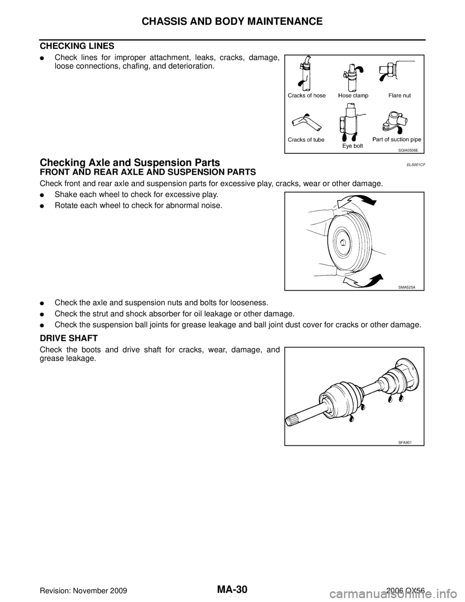
CHECKING LINES
�Check lines for improper attachment, leaks, cracks, damage,
loose connections, chafing, and deterioration.
Checking Axle and Suspension PartsELS001CF
FRONT AND REAR AXLE AND SUSPENSION PARTS
Check front and rear axle and suspension parts for excessive play, cracks, wear or other damage.
�Shake each wheel to check for excessive play.
�Rotate each wheel to check for abnormal noise.
�Check the axle and suspension nuts and bolts for looseness.
�Check the strut and shock absorber for oil leakage or other damage.
�Check the suspension ball joints for grease leakage and ball joint dust cover for cracks or other damage.
DRIVE SHAFT
Check the boots and drive shaft for cracks, wear, damage, and
grease leakage.
SGIA0506E
SMA525A
SFA901
Page 2630 of 3383
CHASSIS AND BODY MAINTENANCEMA-31
C
DE
F
G H
I
J
K
M A
B
MA
Revision: November 2009 2006 QX56
Lubricating Locks, Hinges and Hood LatchesELS001CG
Lubricate the locks, hinges, and latches at the locations as shown. Refer to MA-11, "Fluids and Lubricants" .
WLIA0024E
Page 2631 of 3383

MA-32
CHASSIS AND BODY MAINTENANCE
Revision: November 20092006 QX56
Checking Seat Belts, Buckles, Retractors, Anchors and AdjustersELS001CH
Check the seat belt buckles, webbing, retractors, anchors and adjusters. Replace any seat belt assembly as
necessary. Refer to SB-11, "
Seat Belt Inspection" .
�Check the seat belt anchors for loose mounting bolts, damage, or excessive wear.
�Check the seat belt webbing for any damage, cuts, fraying, or excessive wear.
�Check the retractor for smooth operation.
�Check the function of the buckles by inserting the seat belt tongue and checking for proper engagement of
the buckle and press the button on the buckle to check for proper release of the seat belt tongue.
CAUTION:
�After any collision, inspect all seat belt assemblies, including retractors and other attached com-
ponents, such as the guide rail set. NISSAN recommends replacing all seat belt assemblies in use
during a collision, unless they are not damaged and are inspected to confirm they are operating
properly after a minor collision.
Also inspect all seat belt assemblies that are not in use during a collision, and replace any compo-
nents if damaged or not operating properly. The seat belt pre-tensioner should be replaced even if
the seat belts are not in use during a frontal collision where the driver and passenger air bags
have been deployed.
�If any component of the seat belt assembly is suspected of being damaged or not operating prop-
erly, do not repair the component. Replace the components as an assembly.
�If the seat belt webbing is cut, frayed, or damaged then replace the seat belt assembly.
�Never lubricate the seat belt buckle or tongue.
�When replacing any seat belt assembly always use a Genuine NISSAN seat belt assembly.