Page 2833 of 3383

RFD-28
REAR FINAL DRIVE ASSEMBLY
Revision: November 20092006 QX56
Differential Assembly
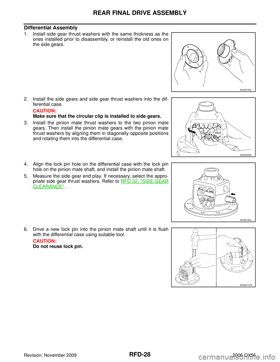
1. Install side gear thrust washers with the same thickness as the
ones installed prior to disassembly, or reinstall the old ones on
the side gears.
2. Install the side gears and side gear thrust washers into the dif- ferential case.
CAUTION:
Make sure that the circular clip is installed to side gears.
3. Install the pinion mate thrust washers to the two pinion mate gears. Then install the pinion mate gears with the pinion mate
thrust washers by aligning them in diagonally opposite positions
and rotating them into the differential case.
4. Align the lock pin hole on the differential case with the lock pin hole on the pinion mate shaft, and install the pinion mate shaft.
5. Measure the side gear end play. If necessary, select the appro- priate side gear thrust washers. Refer to RFD-32, "
SIDE GEAR
CLEARANCE" .
6. Drive a new lock pin into the pinion mate shaft until it is flush with the differential case using suitable tool.
CAUTION:
Do not reuse lock pin.
SDIA0193J
SDIA2025E
SDIA0195J
WDIA0131E
Page 2834 of 3383

REAR FINAL DRIVE ASSEMBLYRFD-29
CE F
G H
I
J
K L
M A
B
RFD
Revision: November 2009 2006 QX56
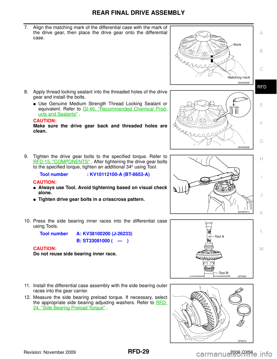
7. Align the matching mark of the differential case with the mark of
the drive gear, then place the drive gear onto the differential
case.
8. Apply thread locking sealant into the threaded holes of the drive gear and install the bolts.
�Use Genuine Medium Strength Thread Locking Sealant or
equivalent. Refer to GI-46, "
Recommended Chemical Prod-
ucts and Sealants" .
CAUTION:
Make sure the drive gear back and threaded holes are
clean.
9. Tighten the drive gear bolts to the specified torque. Refer to RFD-15, "
COMPONENTS" . After tightening the drive gear bolts
to the specified torque, tighten an additional 34 ° using Tool.
CAUTION:
�Always use Tool. Avoid tightening based on visual check
alone.
�Tighten drive gear bolts in a crisscross pattern.
10. Press the side bearing inner races into the differential case using Tools.
CAUTION:
Do not reuse side bearing inner race.
11. Install the differential case assembly with the side bearing outer races into the gear carrier.
12. Measure the side bearing preload torque. If necessary, select the appropriate side bearing adjusting washers. Refer to RFD-
24, "Side Bearing Preload Torque" .
SDIA2593E
SDIA2594E
Tool number : KV10112100-A (BT-8653-A)
SDIA0247J
Tool number A: KV38100200 (J-26233)
B: ST33081000 ( — )
SPD353
SPD919
Page 2837 of 3383

RFD-32
SERVICE DATA AND SPECIFICATIONS (SDS)
Revision: November 20092006 QX56
SERVICE DATA AND SPECIFICATIONS (SDS)PFP:00030
General SpecificationsEDS0044V
Inspection and AdjustmentEDS0044W
DRIVE GEAR RUNOUT
Unit: mm (in)
SIDE GEAR CLEARANCE
Unit: mm (in)
PRELOAD TORQUE
Unit: N·m (kg-m, in-lb)
BACKLASH
Unit: mm (in)
COMPANION FLANGE RUNOUT
Unit: mm (in)
SELECTIVE PARTS
Side Gear Thrust Washer
Unit: mm (in)
*: Always check with the Parts Department for the latest parts information. Applied model
VK56DE
2WD 4WD
Final drive model R230
Gear ratio 2.9373.357
Number of teeth (Drive gear/Drive pinion) 47 / 1647 / 14
Oil capacity (Approx.) 1.75 (3 3/4 US pt, 3 1/8 Imp pt)
Number of pinion gears 2
Drive pinion adjustment spacer type Collapsible
ItemRunout limit
Drive gear back face 0.05 (0.0020) or less
ItemSpecification
Side gear back clearance
(Clearance limit between side gear and differential case for adjusting
side gear backlash) 0.20 (0.0079) or less
(Each gear should rotate smoothly without excessive resis- tance during differential motion.)
Item Specification
Drive pinion bearing preload torque 1.77 − 2.64 N·m (0.18 − 0.26 kg−m, 16 − 23 in-lb)
Side bearing preload torque (reference value determined by drive
gear bolt pulling force) 0.20
− 0.52 N·m (0.02 − 0.05 kg −m, 2 − 4 in-lb)
Drive gear bolt pulling force (by spring gauge) 34.2 − 39.2 N (3.5 − 4 kg, 7.7 − 8.8 lb)
Total preload torque
(Total preload torque = drive pinion bearing preload torque + Side
bearing preload torque) 2.05
− 4.11 N·m (0.21 − 0.42 kg −m, 19 − 36 in-lb)
Item Specification
Drive gear to drive pinion gear 0.13 − 0.18 (0.0051 − 0.0070)
Item Runout limit
Outer side of the companion flange 0.08 (0.0031) or less
ThicknessPart number*
1.75 (0.0688)
1.80 (0.0708)
1.85 (0.0728) 38424 7S000
38424 7S001
38424 7S002
Page 2844 of 3383

NOISE, VIBRATION, AND HARSHNESS (NVH) TROUBLESHOOTINGRSU-5
C
DF
G H
I
J
K L
M A
B
RSU
Revision: November 2009 2006 QX56
NOISE, VIBRATION, AND HARSHNESS (NVH) TROUBLESHOOTINGPFP:00003
NVH Troubleshooting ChartEES001H1
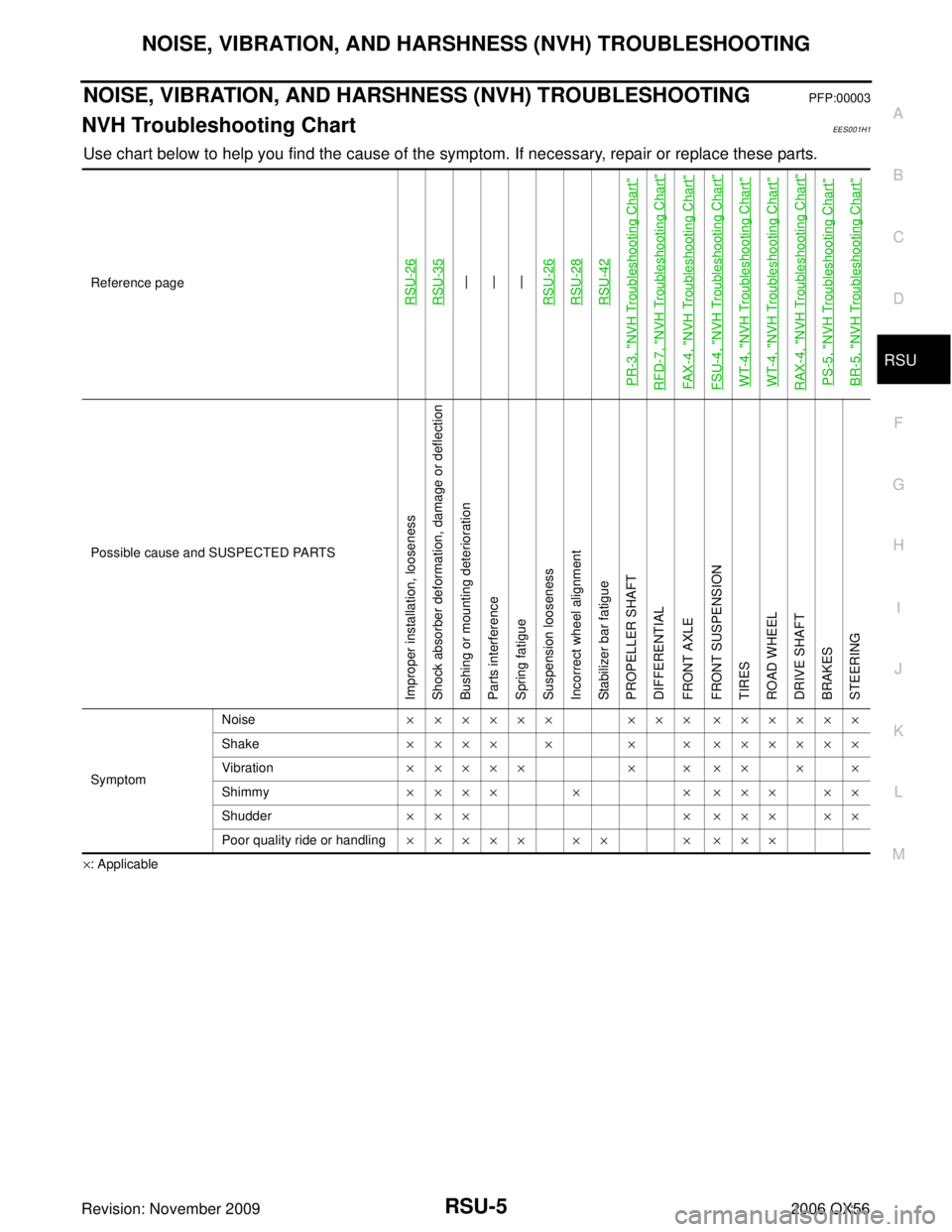
Use chart below to help you find the cause of the symptom. If necessary, repair or replace these parts.
×: ApplicableReference page
RSU-26RSU-35
—
—
—
RSU-26
RSU-28RSU-42
PR-3, "
NVH Troubleshooting Chart
"
RFD-7, "
NVH Troubleshooting Chart
"
FAX-4, "
NVH Troubleshooting Chart
"
FSU-4, "
NVH Troubleshooting Chart
"
WT-4, "
NVH Troubleshooting Chart
"
WT-4, "
NVH Troubleshooting Chart
"
RAX-4, "
NVH Troubleshooting Chart
"
PS-5, "
NVH Troubleshooting Chart
"
BR-5, "
NVH Troubleshooting Chart
"
Possible cause and SUSPECTED PARTS
Improper installation, looseness
Shock absorber deformation, damage or deflection
Bushing or mounting deterioration
Parts interference
Spring fatigue
Suspension looseness
Incorrect wheel alignment
Stabilizer bar fatigue
PROPELLER SHAFT
DIFFERENTIAL
FRONT AXLE
FRONT SUSPENSION
TIRES
ROAD WHEEL
DRIVE SHAFT
BRAKES
STEERING
Symptom Noise
×××××× ××× ××××××
Shake ×××× × × × ××××××
Vibration ××××× × × ×× × ×
Shimmy ×××× × × ××× ××
Shudder ××× × ××× ××
Poor quality ride or handling ××××× ×× × ×××
Page 3293 of 3383

WT-4
NOISE, VIBRATION, AND HARSHNESS (NVH) TROUBLESHOOTING
Revision: November 20092006 QX56
NOISE, VIBRATION, AND HARSHNESS (NVH) TROUBLESHOOTINGPFP:00003
NVH Troubleshooting ChartEES001HY
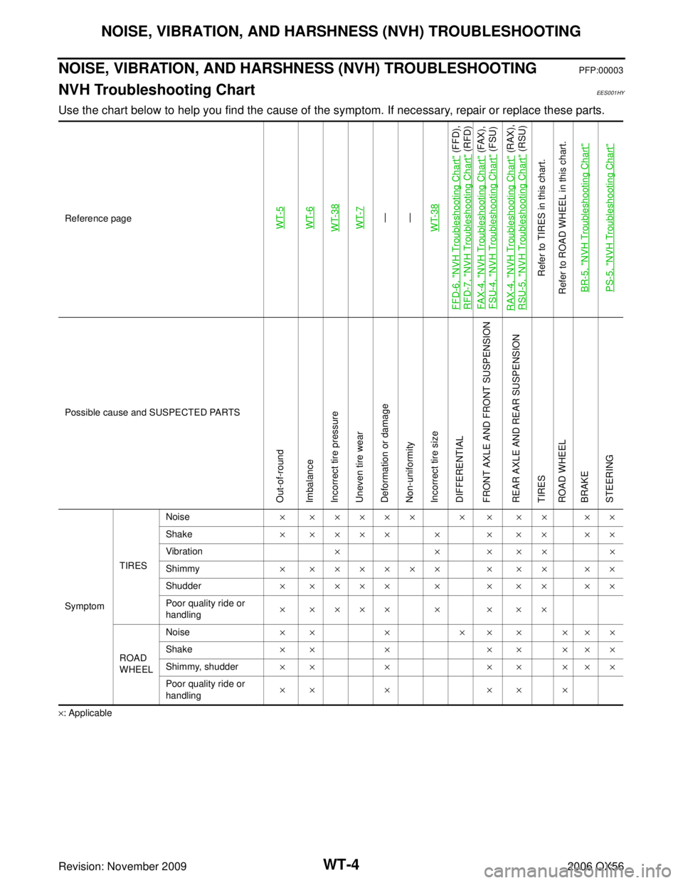
Use the chart below to help you find the cause of the symptom. If necessary, repair or replace these parts.
×: ApplicableReference page
WT-5WT-6WT-38WT-7—
—
WT-38
FFD-6, "
NVH Troubleshooting Chart
" (FFD),
RFD-7, "
NVH Troubleshooting Chart
" (RFD)
FAX-4, "
NVH Troubleshooting Chart
" (FAX),
FSU-4, "
NVH Troubleshooting Chart
" (FSU)
RAX-4, "
NVH Troubleshooting Chart
" (RAX),
RSU-5, "
NVH Troubleshooting Chart
" (RSU)
Refer to TIRES in this chart.
Refer to ROAD WHEEL in this chart.
BR-5, "
NVH Troubleshooting Chart
"
PS-5, "
NVH Troubleshooting Chart
"
Possible cause and SUSPECTED PARTS
Out-of-round
Imbalance
Incorrect tire pressure
Uneven tire wear
Deformation or damage
Non-uniformity
Incorrect tire size
DIFFERENTIAL
FRONT AXLE AND FRONT SUSPENSION
REAR AXLE AND REAR SUSPENSION
TIRES
ROAD WHEEL
BRAKE
STEERING
Symptom TIRESNoise
× ××××× × × ×× ××
Shake × ×××× × × ×× ××
Vibration ××××××
Shimmy × ×××××× × ×× ××
Shudder × ×××× × × ×× ××
Poor quality ride or
handling × ×××× × × ××
ROAD
WHEEL Noise
×××× ×××××
Shake ×× × ×× ×××
Shimmy, shudder ×× × ×× ×××
Poor quality ride or
handling ×× ×
×× ×