Page 3003 of 3383

SE-72
AUTOMATIC DRIVE POSITIONER
Revision: November 20092006 QX56
Door Mirror Remote Control Switch Ground Circuit InspectionEIS004YF
1. CHECK DOOR MIRROR REMOTE CONTROL SWITCH GROUND CIRCUIT
1. Turn ignition switch OFF.
2. Disconnect door mirror remote control switch.
3. Check continuity between door mirror remote control switch con- nector D10 terminal 13 and ground.
OK or NG
OK >> GO TO 2.
NG >> Repair or replace harness.
2. CHECK DOOR MIRROR REMOTE CONTROL SWITCH (CHANGEOVER SWITCH)
Check continuity between door mirror remote control switch termi-
nals as follows.
OK or NG
OK >> Check the condition of the harness and the connector.
NG >> Replace door mirror remote control switch.
Seat Memory Switch Circuit InspectionEIS004YG
1. CHECK FUNCTION
With CONSULT-II
With “SET SW, MEMORY SW1, MEMORY SW2 ” on the DATA
MONITOR, operate the switch to check ON/OFF operation.
Without CONSULT-II
GO TO 2.
OK or NG
OK >> Seat memory switch circuit is OK.
NG >> GO TO 2. 13 - Ground
: Continuity should exist.
LIIA1825E
Terminals ConditionContinuity
3 13Changeover switch RIGHT position Yes
Other than above
No
2 Changeover switch LEFT position Yes
Other than above
No
LIIA2052E
Monitor item [OPERATION or
UNIT] Contents
MEMORY SW1 “ON/OFF ”ON/OFF status judged from the seat
memory switch 1 signal is displayed.
MEMORY SW2 “ON/OFF ”ON/OFF status judged from the seat
memory switch 2 signal is displayed.
SET SW “ON/OFF ”ON/OFF status judged from the setting
switch signal is displayed.
PIIA0309E
Page 3005 of 3383

SE-74
AUTOMATIC DRIVE POSITIONER
Revision: November 20092006 QX56
Seat Memory Indicator Lamp Circuit InspectionEIS004YH
1. CHECK FUNCTION
With CONSULT-II
With “MEMORY SW INDCTR ” in ACTIVE TEST, check operation.
Without CONSULT-II
GO TO 2.
OK or NG
OK >> Seat memory switch indicator lamp circuit is OK.
NG >> GO TO 2.
2. CHECK SEAT MEMORY SWITCH POWER SUPPLY CIRCUIT
1. Turn ignition switch OFF.
2. Disconnect seat memory switch.
3. Check voltage between seat memory switch connector D5 ter- minal 5 and ground.
OK or NG
OK >> GO TO 3.
NG >> Repair or replace harness.
3. CHECK SEAT MEMORY INDICATOR CIRCUIT HARNESS CONTINUITY
1. Turn ignition switch OFF.
2. Disconnect automatic drive positioner control unit.
3. Check continuity between automatic drive positioner control unit connector M33 terminals 12, 13 and seat memory switch con-
nector D5 terminals 6, 7.
4. Check continuity between automatic drive positioner control unit connector M33 terminals 12, 13 and ground.
OK or NG
OK >> GO TO 4.
NG >> Repair or replace harness.
Test item Description
MEMORY SW INDCTR The memory switch indicator is lit by receiving the
drive signal.
PIIA0319E
5 - Ground
: Battery voltage
PIIA4595E
12 - 6 : Continuity should exist.
13 - 7 : Continuity should exist.
12 - Ground : Continuity should not exist.
13 - Ground : Continuity should not exist.
LIIA1022E
Page 3006 of 3383

AUTOMATIC DRIVE POSITIONERSE-75
C
DE
F
G H
J
K L
M A
B
SE
Revision: November 2009 2006 QX56
4. CHECK SEAT MEMORY SWITCH INDICATOR SIGNAL
1. Connect seat memory switch.
2. Turn ignition switch ON.
3. Check voltage between automatic drive positioner control unit connector M33 terminals 12, 13 and ground.
OK or NG
OK >> Replace automatic drive positioner control unit.
NG >> Replace seat memory switch.
Door Mirror Sensor Power Supply and Ground Circuit inspectionEIS004YI
1. CHECK DOOR MIRROR SENSOR CIRCUIT HARNESS CONTINUITY
1. Disconnect automatic drive positioner control unit and door mir- ror (LH and RH).
2. Check continuity between automatic drive positioner control unit connector M34 terminals 33, 41 and door mirror connector D4
(LH), D107 (RH) terminals 5, 6.
3. Check continuity between automatic drive positioner control unit connector M34 terminals 33, 41 and ground.
OK or NG
OK >> GO TO 2.
NG >> Repair or replace harness.
2. CHECK MIRROR SENSOR POWER SUPPLY
1. Connect automatic drive positioner control unit and door mirror LH.
2. Turn ignition switch to ACC.
3. Check voltage between automatic drive positioner control unit connector M34 terminal 33 and ground.
OK or NG
OK >> GO TO 3.
NG >> Replace automatic drive positioner control unit. 12 - Ground
: Battery voltage
13 - Ground : Battery voltage
LIIA1134E
33 - 5 : Continuity should exist.
41 - 6 : Continuity should exist.
33 - Ground : Continuity should not exist.
41 - Ground : Continuity should not exist.
LIIA1023E
33 - Ground : Approx. 5V
LIIA1136E
Page 3007 of 3383

SE-76
AUTOMATIC DRIVE POSITIONER
Revision: November 20092006 QX56
3. CHECK MIRROR SENSOR GROUND CIRCUIT
1. Turn ignition switch OFF.
2. Check continuity between automatic drive positioner control unit connector M34 terminal 41 and ground.
OK or NG
OK >> Check the condition of the harness and connector.
NG >> Replace automatic drive positioner control unit.
A/T Device (Park Position Switch) Circuit InspectionEIS004YJ
1. CHECK FUNCTION
With CONSULT-II
Check that when the A/T selector lever is in P position, “DETENT
SW ” on the DATA MONITOR becomes OFF.
Without CONSULT-II
GO TO 2.
OK or NG
OK >> A/T device (park position switch) circuit is OK.
NG >> GO TO 2.
2. CHECK A/T DEVICE (PARK POSITION SWITCH) HARNESS
1. Turn ignition switch OFF.
2. Disconnect A/T device and driver seat control unit.
3. Check continuity between A/T device connector M203 terminal 6 and driver seat control unit connector P2 terminal 21.
4. Check continuity between A/T device connector M203 terminal 6 and ground.
OK or NG
OK >> GO TO 3.
NG >> Repair or replace harness. 41 - Ground
: Continuity should exist.
LIIA1135E
Monitor item
[OPERATION or UNIT] Contents
DETENT SW “
ON/
OFF ”The A/T selector lever position
“P position (OFF)/other
than P position (ON) ” judged from the park position
switch signal is displayed.
PIIA0291E
6 - 21 : Continuity should exist.
6 - Ground : Continuity should not exist.
LIIA1024E
Page 3008 of 3383
 terminals
as follow")
AUTOMATIC DRIVE POSITIONERSE-77
C
DE
F
G H
J
K L
M A
B
SE
Revision: November 2009 2006 QX56
3. CHECK PARK POSITION SWITCH
Check continuity between A/T device (park position switch) terminals
as follows.
OK or NG
OK >> A/T device is OK.
NG >> Replace A/T device.
Steering Wheel Tilt Switch Circuit InspectionEIS004YK
1. CHECK FUNCTION
With CONSULT-II
With “TILT SW-UP, TILT SW-DOWN ” on the DATA MONITOR, oper-
ate the ADP steering wheel tilt switch to check ON/OFF operation.
Without CONSULT-II
1. Turn ignition switch OFF.
2. Check voltage between automatic drive positioner control unit connector and ground.
OK or NG
OK >> ADP steering wheel tilt switch circuit is OK.
NG >> GO TO 2.
Terminals ConditionContinuity
56 P position
No
Other than P position Yes
LIIA1491E
Monitor item [OPERATION or
UNIT] Contents
TILT SW-UP “ON/OFF ”Operation (ON)/open (OFF) status
judged from the tilt switch (FR) signal is
displayed.
TILT SW-DOWN “ON/OFF ”Operation (ON)/open (OFF) status
judged from the tilt switch (RR) signal is
displayed.
PIIA0315E
Connector
Te r m i n a l s
ConditionVoltage (V)
(Approx.)
(+) (-)
M33 1
Ground Tilt switch ON (UP operation) 0
Other than above
5
17 Tilt switch ON (DOWN opera-
tion)
0
Other than above 5
LIIA0491E
Page 3011 of 3383

SE-80
AUTOMATIC DRIVE POSITIONER
Revision: November 20092006 QX56
UART Communication Line Circuit InspectionEIS004YM
1. CHECK UART LINE INPUT/OUTPUT SIGNAL 1
1. Turn ignition switch OFF.
2. Check signal between driver seat control unit connector and ground, with oscilloscope.
OK or NG
OK >> GO TO 2.
NG >> Check the following.
�When voltage wave form does not appear with a constant voltage (approx. 5V), replace driver
seat control unit.
�When voltage wave form does not appear with a constant voltage (approx. 0V), replace auto-
matic driver seat control unit.
2. CHECK UART LINE INPUT/OUTPUT SIGNAL 2
Check signal between automatic drive positioner control unit con-
nector ground, with oscilloscope.
OK or NG
OK >> GO TO 3.
NG >> Check the following.
�When voltage wave form does not appear with a constant voltage (approx. 5V), replace auto-
matic drive positioner control unit.
�When voltage wave form does not appear with a constant voltage (approx. 0V), replace driver
seat control unit.
Connector Te r m i n a l s
Condition Signal
(+) (-)
P2 17 Ground Pedal
adjusting
switch ON
(FOR-
WARD or
BACK-
WARD
operation)
PIIA4599E
PIIA4814E
Connector
Te r m i n a l s
Condition Signal
(+) (-)
M33 10 Ground Pedal
adjusting
switch ON
(FOR-
WARD or
BACK-
WARD
operation)
PIIA4816E
PIIA4813E
Page 3059 of 3383
EHS001BA
CONSULT-II can display each diagnostic item using the diagnostic test modes shown following.
CONSULT-II")
SRS-18
TROUBLE DIAGNOSIS
Revision: November 20092006 QX56
CONSULT-II Function (AIR BAG)EHS001BA
CONSULT-II can display each diagnostic item using the diagnostic test modes shown following.
CONSULT-II FunctionEHS0016Q
HOW TO CHANGE SELF-DIAGNOSIS MODE WITH CONSULT-II
From User Mode to Diagnosis Mode
After selecting “AIR BAG ” on the “SELECT SYSTEM ” screen, User mode automatically changes to Diagnosis
mode.
From Diagnosis Mode to User Mode
To return to User mode from Diagnosis mode, touch “BACK” key of CONSULT-II until “SELECT SYSTEM”
appears, Diagnosis mode automatically changes to User mode.
AIR BAG diagnostic mode Description
SELF-DIAG [CURRENT] A current Self-diagnosis result (also indicated by the number of warning lamp flashes in the Diagnosis
mode) is displayed on the CONSULT-II screen in real time. This refers to a malfunctioning part requir-
ing repairs.
SELF-DIAG [PAST] Diagnosis results previously stored in the memory are displayed on the CONSULT-II screen. The
stored results will remain until memory erasing is executed.
TROUBLE DIAG RECORD With TROUBLE DIAG RECORD, diagnosis results previously erased by a reset operation can be dis-
played on the CONSULT-II screen.
ECU DISCRIMINATED NO. The air bag diagnosis sensor unit for each vehicle
model is assigned with its own, individual classifi-
cation number. This number will be displayed on
the CONSULT-II screen, as shown. When replac-
ing the air bag diagnosis sensor unit, refer to the
part number for the compatibility. After installation,
replacement with a correct unit can be checked by
confirming this classification number on the CON-
SULT-II screen.
The air bag diagnosis sensor unit discrimi-
nated number assigned is F62F.
PASSENGER AIR BAG The STATUS (readiness) of the front passenger air
bag module is displayed. The STATUS displayed
(ON/OFF) depends on the signals supplied to the
occupant classification system control module and
air bag diagnosis sensor unit. Refer to
SRS-6,
"Occupant Classification System (OCS)" for more
information.
ARS366
WHIA0290E
SRS803
Page 3089 of 3383
SRS-48
SPIRAL CABLE
Revision: November 20092006 QX56
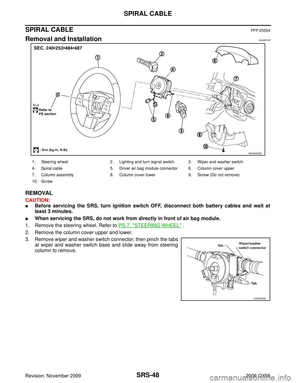
SPIRAL CABLEPFP:25554
Removal and InstallationEHS0016Y
REMOVAL
CAUTION:
�Before servicing the SRS, turn ignition switch OFF, disconnect both battery cables and wait at
least 3 minutes.
�When servicing the SRS, do not work from directly in front of air bag module.
1. Remove the steering wheel. Refer to PS-7, "
STEERING WHEEL" .
2. Remove the column cover upper and lower.
3. Remove wiper and washer switch connector, then pinch the tabs at wiper and washer switch base and slide away from steering
column to remove.
WHIA0233E
1. Steering wheel 2. Lighting and turn signal switch 3. Wiper and washer switch
4. Spiral cable 5. Driver air bag module connector 6. Column cover upper
7. Column assembly 8. Column cover lower 9. Screw (Do not remove)
10. Screw
LHIA0034E