Page 3228 of 3383

TROUBLE DIAGNOSIS FOR SYMPTOMSTF-123
CE F
G H
I
J
K L
M A
B
TF
Revision: November 2009 2006 QX56
4. CHECK HARNESS BETWEEN TRANSFER CONTROL UNIT AND COMBINATION METER
1. Turn ignition switch “OFF”. (Stay for at least 5 seconds.)
2. Disconnect transfer control unit harness connector and combination meter harness connector.
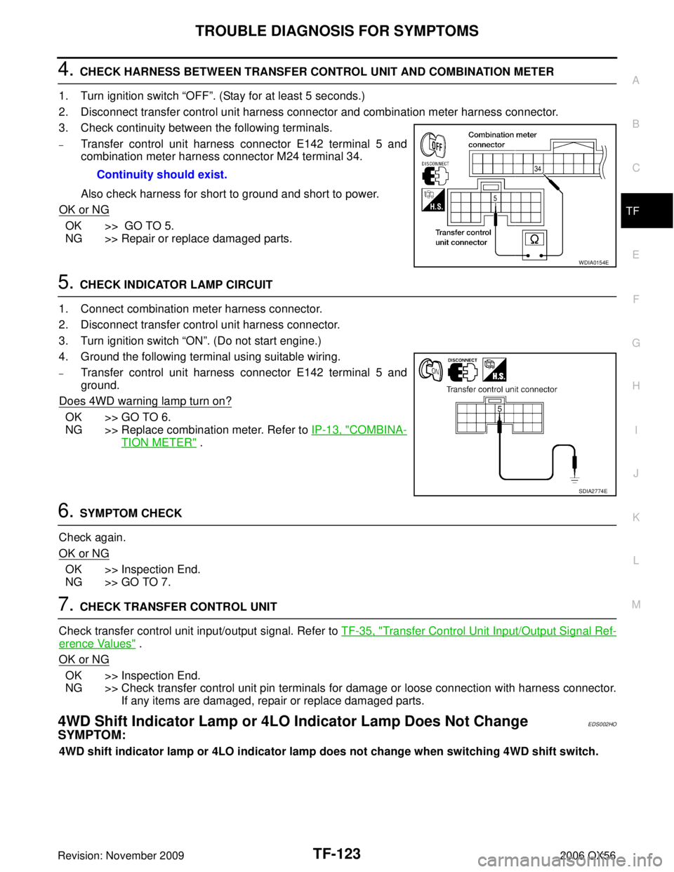
3. Check continuity between the following terminals.
–Transfer control unit harness connector E142 terminal 5 and
combination meter harness connector M24 terminal 34.
Also check harness for short to ground and short to power.
OK or NG
OK >> GO TO 5.
NG >> Repair or replace damaged parts.
5. CHECK INDICATOR LAMP CIRCUIT
1. Connect combination meter harness connector.
2. Disconnect transfer control unit harness connector.
3. Turn ignition switch “ON”. (Do not start engine.)
4. Ground the following terminal using suitable wiring.
–Transfer control unit harness connector E142 terminal 5 and
ground.
Does 4WD warning lamp turn on?
OK >> GO TO 6.
NG >> Replace combination meter. Refer to IP-13, "
COMBINA-
TION METER" .
6. SYMPTOM CHECK
Check again.
OK or NG
OK >> Inspection End.
NG >> GO TO 7.
7. CHECK TRANSFER CONTROL UNIT
Check transfer control unit input/output signal. Refer to TF-35, "
Transfer Control Unit Input/Output Signal Ref-
erence Values" .
OK or NG
OK >> Inspection End.
NG >> Check transfer control unit pin terminals for damage or loose connection with harness connector. If any items are damaged, repair or replace damaged parts.
4WD Shift Indicator Lamp or 4LO Indicator Lamp Does Not ChangeEDS002HO
SYMPTOM:
4WD shift indicator lamp or 4LO indicator lamp does not change when switching 4WD shift switch.Continuity should exist.
WDIA0154E
SDIA2774E
Page 3231 of 3383

TF-126
TROUBLE DIAGNOSIS FOR SYMPTOMS
Revision: November 20092006 QX56
4. CHECK SYSTEM FOR ATP SWITCH
Perform trouble diagnosis for ATP switch system. Refer to TF-113, "
ATP Switch" .
OK or NG
OK >> GO TO 5.
NG >> Repair or replace damaged parts.
5. CHECK HARNESS BETWEEN TRANSFER CONTROL UNIT AND COMBINATION METER
1. Turn ignition switch “ OFF”. (Stay for at least 5 seconds.)
2. Disconnect transfer control unit harness connector and combination meter harness connector.
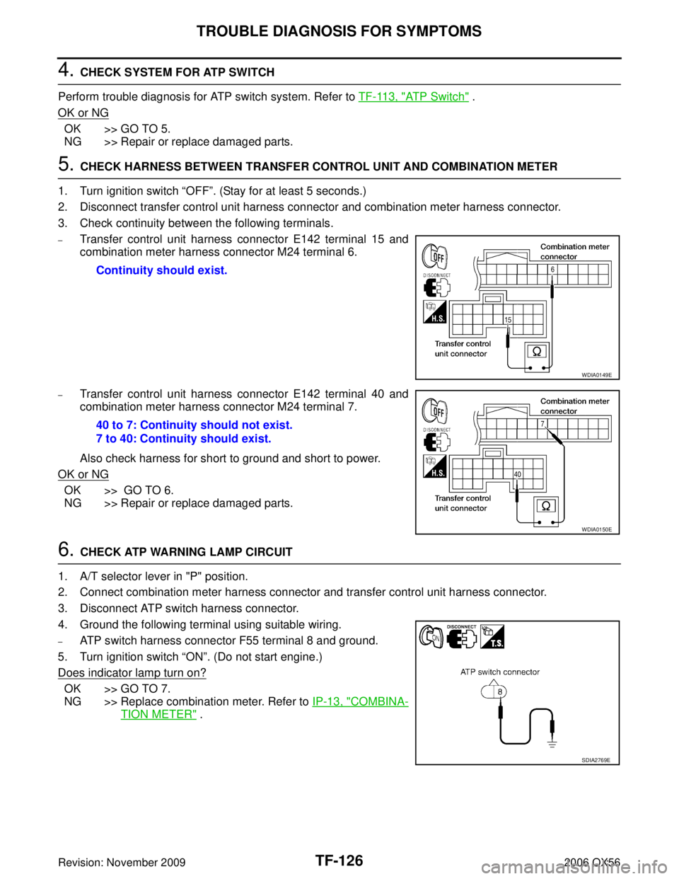
3. Check continuity between the following terminals.
–Transfer control unit harness connector E142 terminal 15 and
combination meter harness connector M24 terminal 6.
–Transfer control unit harness connector E142 terminal 40 and
combination meter harness connector M24 terminal 7.
Also check harness for short to ground and short to power.
OK or NG
OK >> GO TO 6.
NG >> Repair or replace damaged parts.
6. CHECK ATP WARNING LAMP CIRCUIT
1. A/T selector lever in "P" position.
2. Connect combination meter harness connector and transfer control unit harness connector.
3. Disconnect ATP switch harness connector.
4. Ground the following terminal using suitable wiring.
–ATP switch harness connector F55 terminal 8 and ground.
5. Turn ignition switch “ ON”. (Do not start engine.)
Does indicator lamp turn on?
OK >> GO TO 7.
NG >> Replace combination meter. Refer to IP-13, "
COMBINA-
TION METER" .
Continuity should exist.
WDIA0149E
40 to 7: Continuity should not exist.
7 to 40: Continuity should exist.
WDIA0150E
SDIA2769E
Page 3247 of 3383

TF-142
TRANSFER MOTOR
Revision: November 20092006 QX56
TRANSFER MOTORPFP:00000
Removal and InstallationEDS003BD
REMOVAL
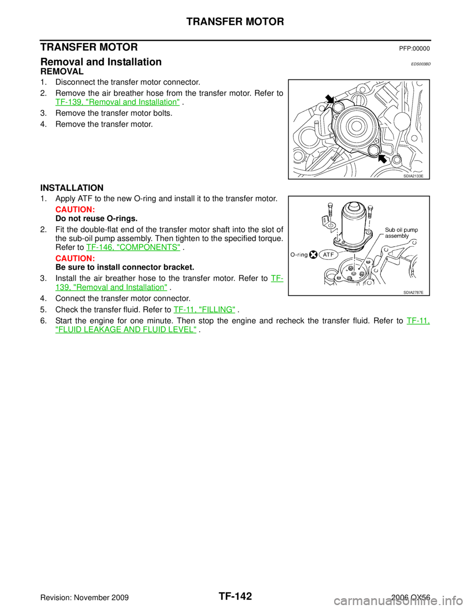
1. Disconnect the transfer motor connector.
2. Remove the air breather hose from the transfer motor. Refer to
TF-139, "
Removal and Installation" .
3. Remove the transfer motor bolts.
4. Remove the transfer motor.
INSTALLATION
1. Apply ATF to the new O-ring and install it to the transfer motor.
CAUTION:
Do not reuse O-rings.
2. Fit the double-flat end of the transfer motor shaft into the slot of the sub-oil pump assembly. Then tighten to the specified torque.
Refer to TF-146, "
COMPONENTS" .
CAUTION:
Be sure to install connector bracket.
3. Install the air breather hose to the transfer motor. Refer to TF-
139, "Removal and Installation" .
4. Connect the transfer motor connector.
5. Check the transfer fluid. Refer to TF-11, "
FILLING" .
6. Start the engine for one minute. Then stop the engine and recheck the transfer fluid. Refer to TF-11,
"FLUID LEAKAGE AND FLUID LEVEL" .
SDIA2133E
SDIA2787E
Page 3249 of 3383
TF-144
TRANSFER OIL FILTER
Revision: November 20092006 QX56
3. Apply ATF to the two new O-rings (1), and install them on the oil
filter (2).
CAUTION:
Do not reuse O-rings.
4. Install the oil filter to the transfer assembly. Tighten the bolts to the specified torque. Refer to TF-146, "
COMPONENTS" .
CAUTION:
�Do not damage oil filter.
�Attach oil filter and tighten bolts evenly.
5. Check the transfer fluid. Refer to TF-11, "
TRANSFER FLUID" .
6. Start the engine and let it run for one minute. Then stop the engine and recheck the transfer fluid. Refer to TF-11, "
TRANS-
FER FLUID" .
WDIA0285E
SDIA2136E
Page 3250 of 3383

TRANSFER ASSEMBLYTF-145
CE F
G H
I
J
K L
M A
B
TF
Revision: November 2009 2006 QX56
TRANSFER ASSEMBLYPFP:33100
Removal and InstallationEDS003BF
REMOVAL
1. Remove the drain plug and gasket. Drain the fluid. Refer to TF-11, "DRAINING" .
2. Remove the A/T undercover using power tool.
3. Remove the center exhaust tube and main muffler. Refer to EX-3, "
Removal and Installation" .
4. Remove the front and rear propeller shafts. Refer to PR-4, "
Removal and Installation" (front), PR-8,
"Removal and Installation" (rear).
CAUTION:
Do not damage spline, sleeve yoke and rear oil seal when removing rear propeller shaft.
NOTE:
Insert a plug into the rear oil seal after removing the rear propeller shaft.
5. Remove the A/T nuts from the A/T crossmember.
6. Position two suitable jacks under the A/T and transfer assembly.
7. Remove the crossmember. Refer to AT- 2 4 6 , "
COMPONENTS" .
WARNING:
Support A/T and transfer assembly using two suitable jacks while removing crossmember.
8. Disconnect the electrical connectors from the following:
�AT P s w i t c h
�Neutral 4LO switch
�Wait detection switch
�Transfer motor
�Transfer control device
�Transfer terminal cord assembly
9. Disconnect each air breather hose from the following. Refer to TF-139, "
Removal and Installation" .
�Actuator
�Breather tube (transfer)
�Transfer motor (case connector)
10. Remove the transfer control device from the extension housing.
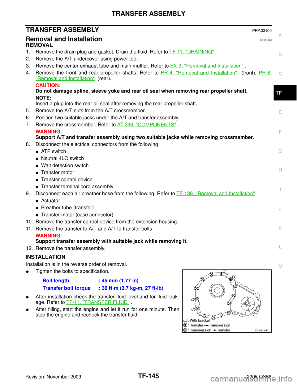
11. Remove the transfer to A/T and A/T to transfer bolts. WARNING:
Support transfer assembly with suitable jack while removing it.
12. Remove the transfer assembly.
INSTALLATION
Installation is in the reverse order of removal.
�Tighten the bolts to specification.
�After installation check the transfer fluid level and for fluid leak-
age. Refer to TF-11, "
TRANSFER FLUID" .
�After filling, start the engine and let it run for one minute. Then
stop the engine and recheck the transfer fluid.Bolt length : 45 mm (1.77 in)
Transfer bolt torque : 36 N·m (3.7 kg-m, 27 ft-lb)
SDIA3181E