Page 2853 of 3383

RSU-14
TROUBLE DIAGNOSIS
Revision: November 20092006 QX56
6. Select the required operation from the "SELECT DIAG MODE"
screen.
For further information, see the CONSULT-II Operation Manual.
SELF-DIAGNOSIS
Description
If an error is detected in the system, perform self-diagnosis as follows:
Operation Procedure
1. Turn ignition switch OFF.
2. Connect CONSULT-II and CONSULT-II CONVERTER to the data link connector.
CAUTION:
If CONSULT-II is used with no connection of CONSULT-II CONVERTER, malfunctions might be
detected in self-diagnosis depending on control unit which carries out CAN communication.
3. Turn ignition switch ON.
4. With the engine running, touch "START (NISSAN BASED VHCL)", "AIR LEVELIZER", "SELF-DIAG RESULTS" in order on the CONSULT-II screen.
CAUTION:
When "START (NISSAN BASED VHCL)" is touched immediately after starting the engine or turning
on the ignition switch, "AIR LEVELIZER" might not be displayed in the "SELECT SYSTEM" screen.
In this case, repeat the operation from step 4.
5. The self-diagnostic results are displayed. (If necessary, the self-diagnostic results can be printed out by touching "COPY".)
�When "NO DTC IS DETECTED" is displayed, check the CK SUSP indicator lamp.
6. Conduct the appropriate inspection from the display item list, and repair or replace the malfunctioning component.
7. Start and run the vehicle for approximately 1 minute.
8. Turn ignition switch OFF to prepare for erasing the memory.
9. Start the engine and touch "START (NISSAN BASED VHCL)", "AIR LEVELIZER", "SELF-DIAG RESULTS", "ERASE" in order on the CONSULT-II screen to erase the error memory.
If "AIR LEVELIZER" is not indicated, go to GI-40, "
CONSULT-II Data Link Connector (DLC) Circuit" .
CAUTION:
If the error memory is not erased, re-conduct the operation from step 7.
10. For the final inspection, start and run the vehicle for approximately 1 minute and confirm that the CK SUSP indicator lamp is off.
Display Item List
BCIA0031E
Self-diagnostic item Malfunction detecting condition Check system
Vehicle height sensor
[C1801] Vehicle height sensor voltage is less than 0.2V or greater than
4.8V for more than 60 seconds. Refer to
RSU-18, "
Height
Sensor System Inspection" .
Compressor relay
[C1802] 1. Driving transistor for compressor relay is off and monitor volt-
age continues high level for more than 10 seconds.
2. Driving transistor for compressor relay is on and monitor volt- age continues low level for more than 5 seconds. Refer to
RSU-21, "
Compres-
sor Motor, Compressor
Motor Relay and Circuit
Inspection" .
Exhaust solenoid
[C1803] 1. Driving transistor for exhaust solenoid is off and monitor volt-
age continues high level for more than 10 seconds.
2. Driving transistor for exhaust solenoid is on and monitor volt- age continues low level for more than 5 seconds. Refer to
RSU-19, "
Exhaust
Valve Solenoid System
Inspection" .
Page 2854 of 3383

TROUBLE DIAGNOSISRSU-15
C
DF
G H
I
J
K L
M A
B
RSU
Revision: November 2009 2006 QX56
WORK SUPPORT
Operation Procedure
1. After turning OFF the ignition switch, connect CONSULT-II and the CONSULT-II CONVERTER to the data
link connector.
CAUTION:
If CONSULT-II is used with no connection of CONSULT-II CONVERTER, malfunctions might be
detected in self-diagnosis depending on control unit which carries out CAN communication.
2. Touch "START (NISSAN BASED VHCL)", "AIR LEVELIZER", "WORK SUPPORT" in order on the CON- SULT-II screen.
If "AIR LEVELIZER" is not indicated, go to GI-40, "
CONSULT-II Data Link Connector (DLC) Circuit" .
CAUTION:
When "START (NISSAN BASED VHCL)" is touched immediately after starting the engine or turning
on the ignition switch, "AIR LEVELIZER" might not be displayed in the "SELECT SYSTEM" screen.
In this case, repeat the operation from step 2.
3. Select "STANDARD HEIGHT LEVEL", "ADJUST HEIGHT INI" or "CLEAR HEIGHT INI" on the "SELECT WORK ITEM" screen.
NOTE:
Read and perform screen instructions if "STANDARD HEIGHT LEVEL" or "ADJUST HEIGHT INI" is
selected.
4. Touch "START" to begin the desired work support.
Display Item List
Vehicle height adjusting trouble
(compressor)
[C1804] Continuous compressor relay ON time is more than 120 sec-
onds. Refer to
RSU-21, "Compres-
sor Motor, Compressor
Motor Relay and Circuit
Inspection" .
Vehicle height adjusting trouble
(exhaust solenoid)
[C1805] Continuous exhaust solenoid ON time is more than 120 seconds. Refer to
RSU-19, "
Exhaust
Valve Solenoid System
Inspection" .
Vehicle height sensor locking trou-
ble
[C1806] Output sensor voltage variation ±
0.02V is more than 100 hour
when vehicle height range is normal. Refer to
RSU-18, "
Height
Sensor System Inspection" .
Sensor 5V trouble
[C1807] Sensor reference voltage is less than 0.8V or more than 6V for
20 seconds. Refer to
RSU-18, "
Height
Sensor System Inspection" .
Integral time trouble by supplying
air
[C1808] Integral discontinuous time on the compressor is more than 180
seconds. Refer to
RSU-21, "
Compres-
sor Motor, Compressor
Motor Relay and Circuit
Inspection" .
Self-diagnostic item
Malfunction detecting condition Check system
ItemDescription Condition
STANDARD HEIGHT LEVEL Resets the vehicle height to the initialization flag
setting stored in the suspension control unit. Vehicle unladen
RSU-49, "
Wheelarch Height
(Unladen*1 )" , set in a horizontal position and
not moving.
NOTE:
Do not take your eyes off the vehicle while
CONSULT-II is processing.
ADJUST HEIGHT INI Sets the height initialization flag in the suspension
control unit when the control unit has been replaced
or when the initialization flag has been cleared
using the "CLEAR HEIGHT INI" procedure. Vehicle unladen
RSU-49, "
Wheelarch Height
(Unladen*1 )" . Move vehicle forward and
backward approx. 5 m (16.4 ft) and rock vehi-
cle from side to side.
NOTE:
Do not move vehicle while CONSULT-II is pro-
cessing.
CLEAR HEIGHT INI Clears the initialization flag in the suspension con-
trol unit. Vehicle unladen
RSU-49, "
Wheelarch Height
(Unladen*1 )" .
Page 2864 of 3383
TROUBLE DIAGNOSES FOR SYMPTOMSRSU-25
C
DF
G H
I
J
K L
M A
B
RSU
Revision: November 2009 2006 QX56
4. CHECK GENERATOR SIGNAL INPUT
1. Start the engine.
2. Check voltage between suspension control unit connector B3 terminal 15 and ground.
OK or NG
OK >> Replace the suspension control unit. Refer to RSU-47,
"CONTROL UNIT" .
NG >> Repair the circuit.
CK SUSP Indicator Lamp Stays On When Ignition Switch Is Turned OnEES001HE
1. CARRY OUT SELF-DIAGNOSIS
Carry out self-diagnosis. Refer to RSU-14, "
SELF-DIAGNOSIS" .
Are malfunctions detected in self-diagnosis?
YES >> Refer to RSU-16, "Display Item List" .
NO >> Refer to DI-31, "
WARNING LAMPS" .
Voltage : Approx. 12V
WEIA0071E
Page 2873 of 3383

RSU-34
REAR SUSPENSION MEMBER
Revision: November 20092006 QX56
INSTALLATION
Installation is in the reverse order of removal.
�When raising the rear suspension member assembly, use the
locating pins to align the rear suspension member to the vehicle
body.
�When installing the upper and lower rubber seats for the rear
coil springs, the arrow embossed on the rubber seats must point
out toward the wheel and tire assembly.
�To connect the rear load leveling air suspension hoses, the lock
ring must be fully seated in the fitting. Insert the hose “B” into the
lock ring “A” until the lock ring “A” is touching the hose “B” as
shown. Pull on the hose to check that it is securely inserted.
�Perform the final tightening of the nuts and bolts for the links (rubber bushing) under unladen condition
(unladen condition means that the fuel tank, engine coolant and lubricants are at the full specification, and
the spare tire, jack, hand tools, and mats are in their designated positions) with the tires on level ground.
�Check the wheel alignment. Refer to RSU-48, "Wheel Alignment" .
LEIA0083E
LEIA0076E
LEIA0078E
Page 2876 of 3383
SUSPENSION ARMRSU-37
C
DF
G H
I
J
K L
M A
B
RSU
Revision: November 2009 2006 QX56
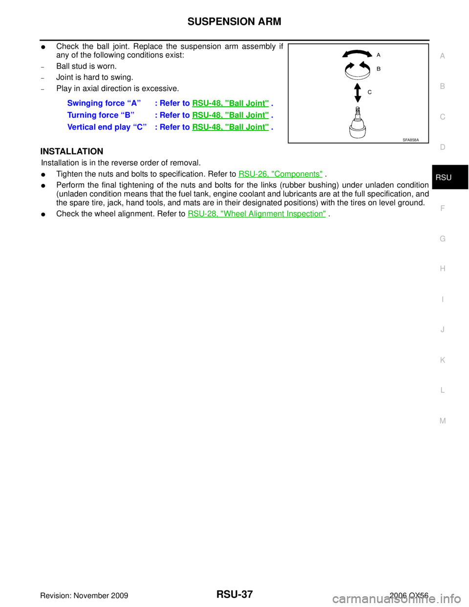
�Check the ball joint. Replace the suspension arm assembly if
any of the following conditions exist:
–Ball stud is worn.
–Joint is hard to swing.
–Play in axial direction is excessive.
INSTALLATION
Installation is in the reverse order of removal.
�Tighten the nuts and bolts to specification. Refer to RSU-26, "Components" .
�Perform the final tightening of the nuts and bolts for the links (rubber bushing) under unladen condition
(unladen condition means that the fuel tank, engine coolant and lubricants are at the full specification, and
the spare tire, jack, hand tools, and mats are in their designated positions) with the tires on level ground.
�Check the wheel alignment. Refer to RSU-28, "Wheel Alignment Inspection" .
Swinging force “A” : Refer to
RSU-48, "
Ball Joint" .
Turning force “B” : Refer to RSU-48, "
Ball Joint" .
Vertical end play “C” : Refer to RSU-48, "
Ball Joint" .
SFA858A
Page 2878 of 3383
FRONT LOWER LINKRSU-39
C
DF
G H
I
J
K L
M A
B
RSU
Revision: November 2009 2006 QX56
INSTALLATION
Installation is in the reverse order of removal.
�Tighten the nuts and bolts to specification. Refer to RSU-26, "Components" .
�Perform the final tightening of the nuts and bolts for the links (rubber bushing) under unladen condition
(unladen condition means that the fuel tank, engine coolant and lubricants are at the full specification, and
the spare tire, jack, hand tools, and mats are in their designated positions) with the tires on level ground.
�Check the wheel alignment. Refer to RSU-28, "Wheel Alignment Inspection" .
Page 2885 of 3383
RSU-46
HEIGHT SENSOR
Revision: November 20092006 QX56
INSTALLATION
Installation is in the reverse order of removal.
1. Start the engine.
2. Use CONSULT-II to perform "STANDARD HEIGHT LEVEL" work support function.
3. Using data monitor of CONSULT-II, verify "HEIGT CALC" is at 0 mm.
4. Check the vehicle height. Refer to RSU-49, "
Wheelarch Height (Unladen*1 )" . If vehicle height is not
within ± 10 mm (0 ± 0.39 in) of the specification, perform the initialization procedure. Refer to RSU-47,
"Initialization Procedure" .
Page 2909 of 3383

SC-4
BATTERY
Revision: November 20092006 QX56
BATTERYPFP:AYBGL
How to Handle BatteryEKS00B78
CAUTION:
�If it becomes necessary to start the engine with a booster battery and jumper cables, use a 12-volt
booster battery.
�After connecting battery cables, ensure that they are tightly clamped to battery terminals for good
contact.
�Never add distilled water through the hole used to check specific gravity.
METHODS OF PREVENTING OVER-DISCHARGE
The following precautions must be taken to prevent over-discharging
a battery.
�The battery surface (particularly its top) should always be kept
clean and dry.
�The terminal connections should be clean and tight.
�At every routine maintenance, check the electrolyte level.
This also applies to batteries designated as “low maintenance”
and “maintenance-free ”.
�When the vehicle is not going to be used over a long period of
time, disconnect the negative battery terminal.
�Check the charge condition of the battery.
Periodically check the specific gravity of the electrolyte. Keep a
close check on charge condition to prevent over-discharge.
CHECKING ELECTROLYTE LEVEL
WARNING:
Do not allow battery fluid to come in contact with skin, eyes, fabrics, or painted surfaces. After touch-
ing a battery, do not touch or rub your eyes until you have thoroughly washed your hands. If acid con-
tacts eyes, skin or clothing, immediately flush with water for 15 minutes and seek medical attention.
MEL040F
MEL041F
MEL042F