Page 1227 of 3383
 “AIR BAG” and “SEAT
BELT PRE-TENSIONER”
UBS00KZ0
The Supplemental R")
EC-16Revision: November 2009
PRECAUTIONS
2006 QX56
PRECAUTIONSPFP:00001
Precautions for Supplemental Restraint System (SRS) “AIR BAG” and “SEAT
BELT PRE-TENSIONER”
UBS00KZ0
The Supplemental Restraint System such as “AIR BAG” and “SEAT BELT PRE-TENSIONER ”, used along
with a front seat belt, helps to reduce the risk or severity of injury to the driver and front passenger for certain
types of collision. This system includes seat belt switch inputs and dual stage front air bag modules. The SRS
system uses the seat belt switches to determine the front air bag deployment, and may only deploy one front
air bag, depending on the severity of a collision and whether the front occupants are belted or unbelted.
Information necessary to service the system safely is included in the SRS and SB section of this Service Man-
ual.
WARNING:
�To avoid rendering the SRS inoperative, which could increase the risk of personal injury or death
in the event of a collision which would result in air bag inflation, all maintenance must be per-
formed by an authorized NISSAN/INFINITI dealer.
�Improper maintenance, including incorrect removal and installation of the SRS, can lead to per-
sonal injury caused by unintentional activation of the system. For removal of Spiral Cable and Air
Bag Module, see the SRS section.
�Do not use electrical test equipment on any circuit related to the SRS unless instructed to in this
Service Manual. SRS wiring harnesses can be identified by yellow and/or orange harnesses or
harness connectors.
On Board Diagnostic (OBD) System of Engine and A/TUBS00KZ1
The ECM has an on board diagnostic system. It will light up the malfunction indicator lamp (MIL) to warn the
driver of a malfunction causing emission deterioration.
CAUTION:
�Be sure to turn the ignition switch OFF and disconnect the negative battery cable before any
repair or inspection work. The open/short circuit of related switches, sensors, solenoid valves,
etc. will cause the MIL to light up.
�Be sure to connect and lock the connectors securely after work. A loose (unlocked) connector will
cause the MIL to light up due to the open circuit. (Be sure the connector is free from water, grease,
dirt, bent terminals, etc.)
�Certain systems and components, especially those related to OBD, may use a new style slide-
locking type harness connector. For description and how to disconnect, refer to PG-68, "
HAR-
NESS CONNECTOR" .
�Be sure to route and secure the harnesses properly after work. The interference of the harness
with a bracket, etc. may cause the MIL to light up due to the short circuit.
�Be sure to connect rubber tubes properly after work. A misconnected or disconnected rubber tube
may cause the MIL to light up due to the malfunction of the EVAP system or fuel injection system,
etc.
�Be sure to erase the unnecessary malfunction information (repairs completed) from the ECM and
TCM (Transmission control module) before returning the vehicle to the customer.
PrecautionUBS00KZ2
�Always use a 12 volt battery as power source.
�Do not attempt to disconnect battery cables while engine is
running.
�Before connecting or disconnecting the ECM harness con-
nector, turn ignition switch OFF and disconnect negative
battery cable. Failure to do so may damage the ECM
because battery voltage is applied to ECM even if ignition
switch is turned OFF.
�Before removing parts, turn ignition switch OFF and then
disconnect negative battery cable.
SEF289H
Page 1228 of 3383

PRECAUTIONSEC-17
C
DE
F
G H
I
J
K L
M A
EC
Revision: November 2009 2006 QX56
�Do not disassemble ECM.
�If a battery cable is disconnected, the memory will return to
the ECM value.
The ECM will now start to self-control at its initial value.
Engine operation can vary slightly when the terminal is dis-
connected. However, this is not an indication of a malfunc-
tion. Do not replace parts because of a slight variation.
�If the battery is disconnected, the following emission-
related diagnostic information will be lost within 24 hours.
–Diagnostic trouble codes
–1st trip diagnostic trouble codes
–Freeze frame data
–1st trip freeze frame data
–System readiness test (SRT) codes
–Test values
�When connecting ECM harness connector, fasten it
securely with a lever as far as it will go as shown in the fig-
ure.
�When connecting or disconnecting pin connectors into or
from ECM, take care not to damage pin terminals (bend or
break).
Make sure that there are not any bends or breaks on ECM
pin terminal, when connecting pin connectors.
�Securely connect ECM harness connectors.
A poor connection can cause an extremely high (surge)
voltage to develop in coil and condenser, thus resulting in
damage to ICs.
�Keep engine control system harness at least 10 cm (4 in)
away from adjacent harness, to prevent engine control sys-
tem malfunctions due to receiving external noise, degraded
operation of ICs, etc.
�Keep engine control system parts and harness dry.
�Before replacing ECM, perform ECM Terminals and Refer-
ence Value inspection and make sure ECM functions prop-
erly. Refer to EC-105, "
ECM Terminals and Reference Value"
.
�Handle mass air flow sensor carefully to avoid damage.
�Do not disassemble mass air flow sensor.
�Do not clean mass air flow sensor with any type of deter-
gent.
�Do not disassemble electric throttle control actuator.
�Even a slight leak in the air intake system can cause seri-
ous incidents.
�Do not shock or jar the camshaft position sensor (PHASE), crankshaft position sensor (POS).
PBIB1164E
BBIA0387E
PBIB0090E
MEF040D
Page 1230 of 3383
PRECAUTIONSEC-19
C
DE
F
G H
I
J
K L
M A
EC
Revision: November 2009 2006 QX56
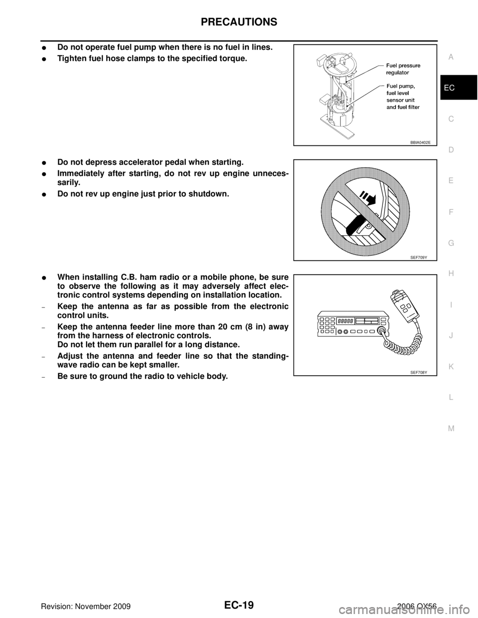
�Do not operate fuel pump when there is no fuel in lines.
�Tighten fuel hose clamps to the specified torque.
�Do not depress accelerator pedal when starting.
�Immediately after starting, do not rev up engine unneces-
sarily.
�Do not rev up engine just prior to shutdown.
�When installing C.B. ham radio or a mobile phone, be sure
to observe the following as it may adversely affect elec-
tronic control systems depending on installation location.
–Keep the antenna as far as possible from the electronic
control units.
–Keep the antenna feeder line more than 20 cm (8 in) away
from the harness of electronic controls.
Do not let them run parallel for a long distance.
–Adjust the antenna and feeder line so that the standing-
wave radio can be kept smaller.
–Be sure to ground the radio to vehicle body.
BBIA0402E
SEF709Y
SEF708Y
Page 1231 of 3383

EC-20Revision: November 2009
PREPARATION
2006 QX56
PREPARATIONPFP:00002
Special Service ToolsUBS00KZ4
The actual shapes of Kent-Moore tools may differ from those of special service tools illustrated here.Tool number
(Kent-Moore No.)
Tool name Description
EG17650301
(J-33984-A)
Radiator cap tester
adapter Adapting radiator cap tester to radiator cap and ra-
diator filler neck
a: 28 (1.10) dia.
b: 31.4 (1.236) dia.
c: 41.3 (1.626) dia.
Unit: mm (in)
KV10117100
(J-36471-A)
Heated oxygen sensor
wrench Loosening or tightening heated oxygen sensors
with 22 mm (0.87 in) hexagon nut
KV10114400
(J-38365)
Heated oxygen sensor
wrench Loosening or tightening heated oxygen sensors
a: 22 mm (0.87 in)
(J-44626)
Air fuel ratio (A/F) sen-
sor wrench Loosening or tightening air fuel ratio (A/F) sensor 1
(J-44321)
Fuel pressure gauge
kit Checking fuel pressure
(J-44321-6)
Fuel pressure adapter Connecting fuel pressure gauge to quick connec-
tor type fuel lines.
(J-45488)
Quick connector re-
lease Remove fuel tube quick connectors in engine
room.
S-NT564
S-NT379
S-NT636
LEM054
LEC642
LBIA0376E
PBIC0198E
Page 1232 of 3383
PREPARATIONEC-21
C
DE
F
G H
I
J
K L
M A
EC
Revision: November 2009 2006 QX56
KV109E0010
(J-46209)
Break-out boxMeasuring the ECM signals with a circuit tester
KV109E0080
(J-45819)
Y-cable adapter Measuring the ECM signals with a circuit tester
(J-23688)
Engine coolant refrac-
tometer Checking concentration of ethylene glycol in en-
gine coolant
Tool number
(Kent-Moore No.)
Tool name
Description
S-NT825
S-NT826
WBIA0539E
Page 1233 of 3383
Description
Leak detector
i.e.: (J-41416) Locating the EVAP leak
EVAP service port
adapt")
EC-22Revision: November 2009
PREPARATION
2006 QX56
Commercial Service ToolsUBS00KZ5
Tool name
(Kent-Moore No.)Description
Leak detector
i.e.: (J-41416) Locating the EVAP leak
EVAP service port
adapter
i.e.: (J-41413-OBD) Applying positive pressure through EVAP service
port
Fuel filler cap adapter
i.e.: (MLR-8382) Checking fuel tank vacuum relief valve opening
pressure
Socket wrench Removing and installing engine coolant tempera- ture sensor
Oxygen sensor thread
cleaner
i.e.: (J-43897-18)
(J-43897-12) Reconditioning the exhaust system threads before
installing a new oxygen sensor. Use with anti-
seize lubricant shown below.
a: 18 mm diameter with pitch 1.5 mm for Zirco-
nia Oxygen Sensor
b: 12 mm diameter with pitch 1.25 mm for Tita-
nia Oxygen Sensor
Anti-seize lubricant
i.e.: (Permatex
TM
133AR or equivalent
meeting MIL specifica-
tion MIL-A-907) Lubricating oxygen sensor thread cleaning tool
when reconditioning exhaust system threads.
S-NT703
S-NT704
S-NT815
S-NT705
AEM488
S-NT779
Page 1234 of 3383
ENGINE CONTROL SYSTEMEC-23
C
DE
F
G H
I
J
K L
M A
EC
Revision: November 2009 2006 QX56
ENGINE CONTROL SYSTEMPFP:23710
System DiagramUBS00KZ6
PBIB2051E
Page 1235 of 3383
 SystemUBS00KZ7
INPUT/OUTPUT SIGNAL CHART
*1: This sensor is not used to control the engine system. This is u")
EC-24Revision: November 2009
ENGINE CONTROL SYSTEM
2006 QX56
Multiport Fuel Injection (MFI) SystemUBS00KZ7
INPUT/OUTPUT SIGNAL CHART
*1: This sensor is not used to control the engine system. This is used only for the on board diagnosis.
*2: This signal is sent to the ECM through CAN communication line.
*3: ECM determines the start signal status by the signals of engine speed and battery voltage.
SYSTEM DESCRIPTION
The amount of fuel injected from the fuel injector is determined by the ECM. The ECM controls the length of
time the valve remains open (injection pulse duration). The amount of fuel injected is a program value in the
ECM memory. The program value is preset by engine operating conditions. These conditions are determined
by input signals (for engine speed and intake air) from both the crankshaft position sensor and the mass air
flow sensor.
VARIOUS FUEL INJECTION INCREASE/DECREASE COMPENSATION
In addition, the amount of fuel injected is compensated to improve engine performance under various operat-
ing conditions as listed below.
�During warm-up
�When starting the engine
�During acceleration
�Hot-engine operation
�When selector lever is changed from N to D
�High-load, high-speed operation
�During deceleration
�During high engine speed operation
Sensor Input signal to ECMECM functionActuator
Crankshaft position sensor (POS) Engine speed*
3
Piston position
Fuel injection
& mixture ratio
controlFuel injector
Camshaft position sensor (PHASE)
Mass air flow sensor
Amount of intake air
Engine coolant temperature sensor Engine coolant temperature
Air fuel ratio (A/F) sensor 1 Density of oxygen in exhaust gas
Throttle position sensor Throttle position
Accelerator pedal position sensor Accelerator pedal position
Park/neutral position (PNP) switch Gear position
Knock sensor Engine knocking condition
Battery Battery voltage*
3
Power steering pressure sensorPower steering operation
Heated oxygen sensor 2 Density of oxygen in exhaust gas*
1
ABS actuator and electric unit (control unit)VDC/TCS operation command*2
Air conditioner switch
Air conditioner operation*2
Wheel sensorVehicle speed*2

Break-out boxMeasuring the ECM signals with a circuit tester
KV109E0080
(J-45819)
Y-cable adapter Meas")
