Page 1587 of 3383
EC-376Revision: November 2009
DTC P0443 EVAP CANISTER PURGE VOLUME CONTROL SOLENOID VALVE
2006 QX56
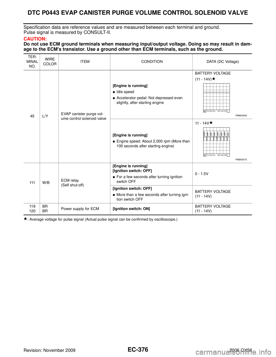
Specification data are reference values and are measured between each terminal and ground.
Pulse signal is measured by CONSULT-II.
CAUTION:
Do not use ECM ground terminals when measuring input/output voltage. Doing so may result in dam-
age to the ECM's transistor. Use a ground other than ECM terminals, such as the ground.
: Average voltage for pulse signal (Actual pulse signal can be confirmed by oscilloscope.)TER-
MINAL NO. WIRE
COLOR ITEM
CONDITION DATA (DC Voltage)
45 L/Y EVAP canister purge vol-
ume control solenoid valve [Engine is running]
�Idle speed
�Accelerator pedal: Not depressed even
slightly, after starting engine
BATTERY VOLTAGE
(11 - 14V)
[Engine is running]
�Engine speed: About 2,000 rpm (More than
100 seconds after starting engine) 11 - 14V
111 W / B ECM relay
(Self shut-off) [Engine is running]
[Ignition switch: OFF]
�For a few seconds after turning ignition
switch OFF
0 - 1.5V
[Ignition switch: OFF]
�More than a few seconds after turning igni-
tion switch OFF BATTERY VOLTAGE
(11 - 14V)
11 9
120 BR
BR
Power supply for ECM
[Ignition switch: ON] BATTERY VOLTAGE
(11 - 14V)
PBIB0050E
PBIB0051E
Page 1588 of 3383
DTC P0443 EVAP CANISTER PURGE VOLUME CONTROL SOLENOID VALVEEC-377
C
DE
F
G H
I
J
K L
M A
EC
Revision: November 2009 2006 QX56
Diagnostic ProcedureUBS00HAY
1. CHECK EVAP CANISTER PURGE VOLUME CONTROL SOLENOID VALVE POWER SUPPLY CIR-
CUIT
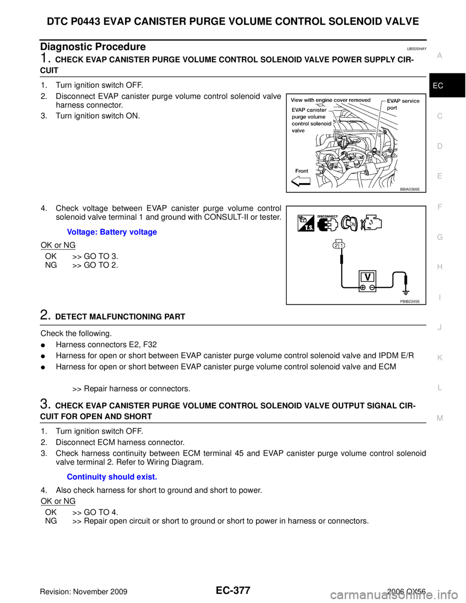
1. Turn ignition switch OFF.
2. Disconnect EVAP canister purge volume control solenoid valve harness connector.
3. Turn ignition switch ON.
4. Check voltage between EVAP canister purge volume control solenoid valve terminal 1 and ground with CONSULT-II or tester.
OK or NG
OK >> GO TO 3.
NG >> GO TO 2.
2. DETECT MALFUNCTIONING PART
Check the following.
�Harness connectors E2, F32
�Harness for open or short between EVAP canister purge volume control solenoid valve and IPDM E/R
�Harness for open or short between EVAP canister purge volume control solenoid valve and ECM
>> Repair harness or connectors.
3. CHECK EVAP CANISTER PURGE VOLUME CONTROL SOLENOID VALVE OUTPUT SIGNAL CIR-
CUIT FOR OPEN AND SHORT1. Turn ignition switch OFF.
2. Disconnect ECM harness connector.
3. Check harness continuity between ECM terminal 45 and EVAP canister purge volume control solenoid valve terminal 2. Refer to Wiring Diagram.
4. Also check harness for short to ground and short to power.
OK or NG
OK >> GO TO 4.
NG >> Repair open circuit or short to ground or short to power in harness or connectors.
BBIA0366E
Voltage: Battery voltage
PBIB2245E
Continuity should exist.
Page 1593 of 3383
EC-382Revision: November 2009
DTC P0444, P0445 EVAP CANISTER PURGE VOLUME CONTROL SOLENOID VALVE
2006 QX56
On Board Diagnosis LogicUBS00H4T
DTC Confirmation ProcedureUBS00H4U
NOTE:
If DTC Confirmation Procedure has been previously conducted, always turn ignition switch OFF and wait at
least 10 seconds before conducting the next test.
TESTING CONDITION:
Before performing the following procedure, confirm battery voltage is more than 11V at idle.
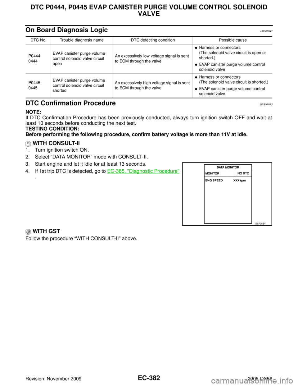
WITH CONSULT-II
1. Turn ignition switch ON.
2. Select “DATA MONITOR ” mode with CONSULT-II.
3. Start engine and let it idle for at least 13 seconds.
4. If 1st trip DTC is detected, go to EC-385, "
Diagnostic Procedure"
.
WITH GST
Follow the procedure “WITH CONSULT-II” above.
DTC No. Trouble diagnosis name DTC detecting conditionPossible cause
P0444
0444 EVAP canister purge volume
control solenoid valve circuit
open An excessively low voltage signal is sent
to ECM through the valve
�Harness or connectors
(The solenoid valve circuit is open or
shorted.)
�EVAP canister purge volume control
solenoid valve
P0445
0445 EVAP canister purge volume
control solenoid valve circuit
shorted An excessively high voltage signal is sent
to ECM through the valve
�Harness or connectors
(The solenoid valve circuit is shorted.)
�EVAP canister purge volume control
solenoid valve
SEF058Y
Page 1595 of 3383
EC-384Revision: November 2009
DTC P0444, P0445 EVAP CANISTER PURGE VOLUME CONTROL SOLENOID VALVE
2006 QX56
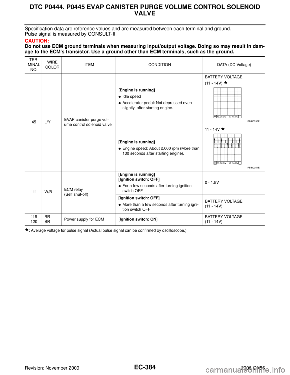
Specification data are reference values and are measured between each terminal and ground.
Pulse signal is measured by CONSULT-II.
CAUTION:
Do not use ECM ground terminals when measuring input/output voltage. Doing so may result in dam-
age to the ECM's transistor. Use a ground other than ECM terminals, such as the ground.
: Average voltage for pulse signal (Actual pulse signal can be confirmed by oscilloscope.)TER-
MINAL NO. WIRE
COLOR ITEM
CONDITION DATA (DC Voltage)
45 L/Y EVAP canister purge vol-
ume control solenoid valve [Engine is running]
�Idle speed
�Accelerator pedal: Not depressed even
slightly, after starting engine.
BATTERY VOLTAGE
(11 - 14V)
[Engine is running]
�Engine speed: About 2,000 rpm (More than
100 seconds after starting engine). 11 - 14V
111 W / B ECM relay
(Self shut-off) [Engine is running]
[Ignition switch: OFF]
�For a few seconds after turning ignition
switch OFF
0 - 1.5V
[Ignition switch: OFF]
�More than a few seconds after turning igni-
tion switch OFF BATTERY VOLTAGE
(11 - 14V)
11 9
120 BR
BR
Power supply for ECM
[Ignition switch: ON] BATTERY VOLTAGE
(11 - 14V)
PBIB0050E
PBIB0051E
Page 1596 of 3383
DTC P0444, P0445 EVAP CANISTER PURGE VOLUME CONTROL SOLENOID VALVE
EC-385
C
D E
F
G H
I
J
K L
M A
EC
Revision: November 2009 2006 QX56
Diagnostic ProcedureUBS00H4W
1. CHECK EVAP CANISTER PURGE VOLUME CONTROL SOLENOID VALVE POWER SUPPLY CIR-
CUIT
1. Turn ignition switch OFF.
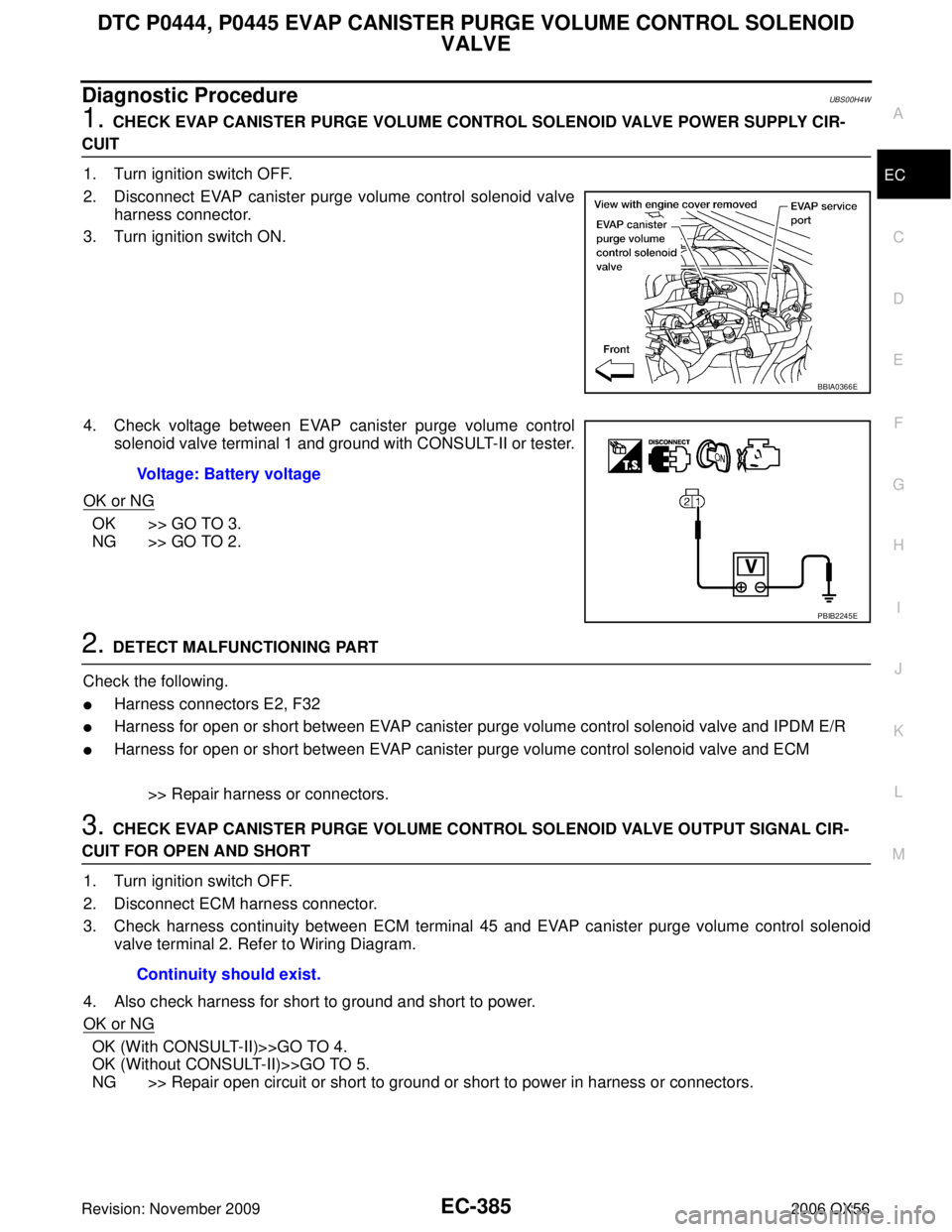
2. Disconnect EVAP canister purge volume control solenoid valve harness connector.
3. Turn ignition switch ON.
4. Check voltage between EVAP canister purge volume control solenoid valve terminal 1 and ground with CONSULT-II or tester.
OK or NG
OK >> GO TO 3.
NG >> GO TO 2.
2. DETECT MALFUNCTIONING PART
Check the following.
�Harness connectors E2, F32
�Harness for open or short between EVAP canister purge volume control solenoid valve and IPDM E/R
�Harness for open or short between EVAP canister purge volume control solenoid valve and ECM
>> Repair harness or connectors.
3. CHECK EVAP CANISTER PURGE VOLUME CONTROL SOLENOID VALVE OUTPUT SIGNAL CIR-
CUIT FOR OPEN AND SHORT1. Turn ignition switch OFF.
2. Disconnect ECM harness connector.
3. Check harness continuity between ECM terminal 45 and EVAP canister purge volume control solenoid valve terminal 2. Refer to Wiring Diagram.
4. Also check harness for short to ground and short to power.
OK or NG
OK (With CONSULT-II)>>GO TO 4.
OK (Without CONSULT-II)>>GO TO 5.
NG >> Repair open circuit or short to ground or short to power in harness or connectors.
BBIA0366E
Voltage: Battery voltage
PBIB2245E
Continuity should exist.
Page 1603 of 3383
EC-392Revision: November 2009
DTC P0447 EVAP CANISTER VENT CONTROL VALVE
2006 QX56
3. CHECK EVAP CANISTER VENT CONTROL VALVE POWER SUPPLY CIRCUIT
1. Turn ignition switch OFF.
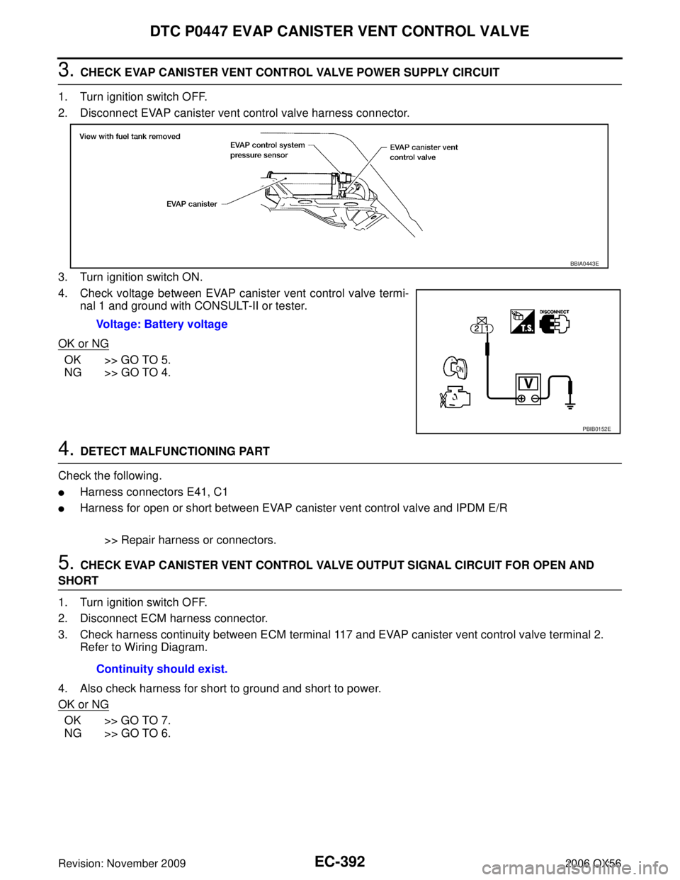
2. Disconnect EVAP canister vent control valve harness connector.
3. Turn ignition switch ON.
4. Check voltage between EVAP canister vent control valve termi- nal 1 and ground with CONSULT-II or tester.
OK or NG
OK >> GO TO 5.
NG >> GO TO 4.
4. DETECT MALFUNCTIONING PART
Check the following.
�Harness connectors E41, C1
�Harness for open or short between EVAP canister vent control valve and IPDM E/R
>> Repair harness or connectors.
5. CHECK EVAP CANISTER VENT CONTROL VALVE OUTPUT SIGNAL CIRCUIT FOR OPEN AND
SHORT
1. Turn ignition switch OFF.
2. Disconnect ECM harness connector.
3. Check harness continuity between ECM terminal 117 and EVAP canister vent control valve terminal 2.Refer to Wiring Diagram.
4. Also check harness for short to ground and short to power.
OK or NG
OK >> GO TO 7.
NG >> GO TO 6. Voltage: Battery voltage
BBIA0443E
PBIB0152E
Continuity should exist.
Page 1617 of 3383
EC-406Revision: November 2009
DTC P0452 EVAP CONTROL SYSTEM PRESSURE SENSOR
2006 QX56
DTC Confirmation ProcedureUBS00H5F
NOTE:
If DTC Confirmation Procedure has been previously conducted, always turn ignition switch OFF and wait at
least 10 seconds before conducting the next test.
TESTING CONDITION:
Always perform test at a temperature of 5°C (41 °F) or more.
WITH CONSULT-II
1. Start engine and warm it up to normal operating temperature.
2. Turn ignition switch OFF and wait at least 10 seconds.
3. Turn ignition switch ON.
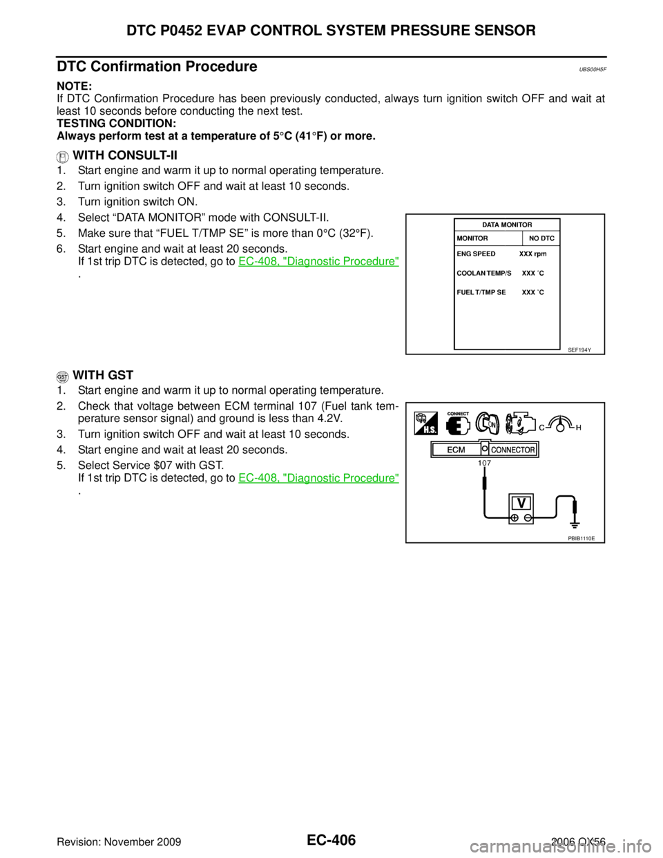
4. Select “DATA MONITOR ” mode with CONSULT-II.
5. Make sure that “FUEL T/TMP SE ” is more than 0°C (32 °F).
6. Start engine and wait at least 20 seconds. If 1st trip DTC is detected, go to EC-408, "
Diagnostic Procedure"
.
WITH GST
1. Start engine and warm it up to normal operating temperature.
2. Check that voltage between ECM terminal 107 (Fuel tank tem-
perature sensor signal) and ground is less than 4.2V.
3. Turn ignition switch OFF and wait at least 10 seconds.
4. Start engine and wait at least 20 seconds.
5. Select Service $07 with GST. If 1st trip DTC is detected, go to EC-408, "
Diagnostic Procedure"
.
SEF194Y
PBIB1110E
Page 1621 of 3383
EC-410Revision: November 2009
DTC P0452 EVAP CONTROL SYSTEM PRESSURE SENSOR
2006 QX56
7. CHECK EVAP CONTROL SYSTEM PRESSURE SENSOR INPUT SIGNAL CIRCUIT FOR OPEN AND
SHORT
1. Check harness continuity between ECM terminal 32 and EVAP control system pressure sensor terminal2.
Refer to Wiring Diagram.
2. Also check harness for short to ground and short to power.
OK or NG
OK >> GO TO 9.
NG >> GO TO 8.
8. DETECT MALFUNCTIONING PART
Check the following.
�Harness connectors C1, E41
�Harness connectors E5, F14
�Harness for open or short between EVAP control system pressure sensor and ECM
>> Repair open circuit or short to ground or short to power in harness or connectors.
9. CHECK EVAP CONTROL SYSTEM PRESSURE SENSOR
Refer to EC-410, "
Component Inspection" .
OK or NG
OK >> GO TO 10.
NG >> Replace EVAP control system pressure sensor.
10. CHECK INTERMITTENT INCIDENT
Refer to EC-144, "
TROUBLE DIAGNOSIS FOR INTERMITTENT INCIDENT" .
>> INSPECTION END
Component InspectionUBS00H5I
EVAP CONTROL SYSTEM PRESSURE SENSOR
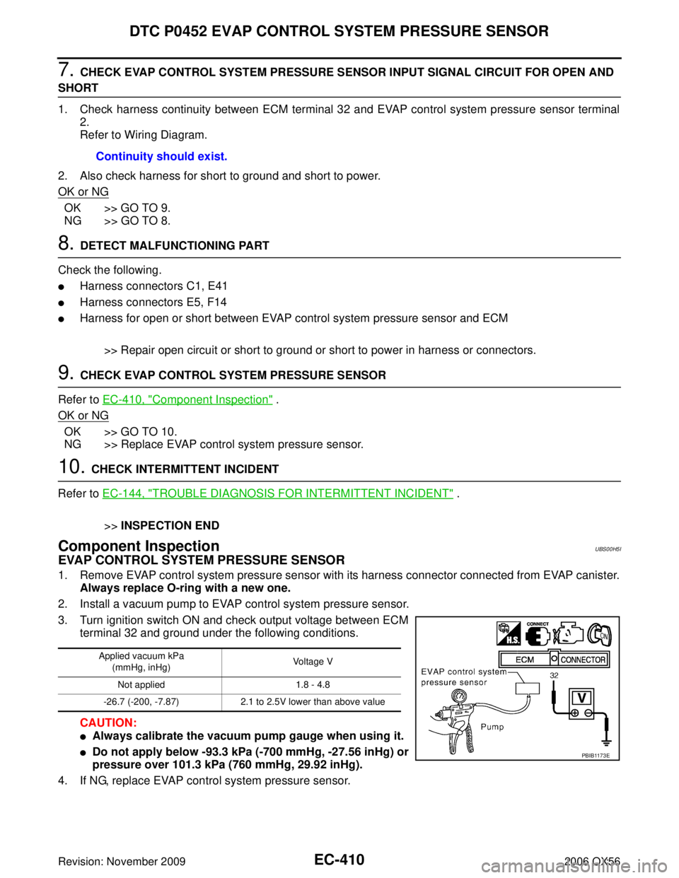
1. Remove EVAP control system pressure sensor with its harness connector connected from EVAP canister.
Always replace O-ring with a new one.
2. Install a vacuum pump to EVAP control system pressure sensor.
3. Turn ignition switch ON and check output voltage between ECM terminal 32 and ground under the following conditions.
CAUTION:
�Always calibrate the vacuum pump gauge when using it.
�Do not apply below -93.3 kPa (-700 mmHg, -27.56 inHg) or
pressure over 101.3 kPa (760 mmHg, 29.92 inHg).
4. If NG, replace EVAP control system pressure sensor. Continuity should exist.
Applied vacuum kPa
(mmHg, inHg) Voltage V
Not applied 1.8 - 4.8
-26.7 (-200, -7.87) 2.1 to 2.5V lower than above value
PBIB1173E