Page 2444 of 3383
HEADLAMP (FOR CANADA) - DAYTIME LIGHT SYSTEM -LT-37
C
DE
F
G H
I
J
L
M A
B
LT
Revision: November 2009 2006 QX56
Wiring Diagram — DTRL —EKS00B8H
WKWA3642E
Page 2449 of 3383

LT-42
HEADLAMP (FOR CANADA) - DAYTIME LIGHT SYSTEM -
Revision: November 20092006 QX56
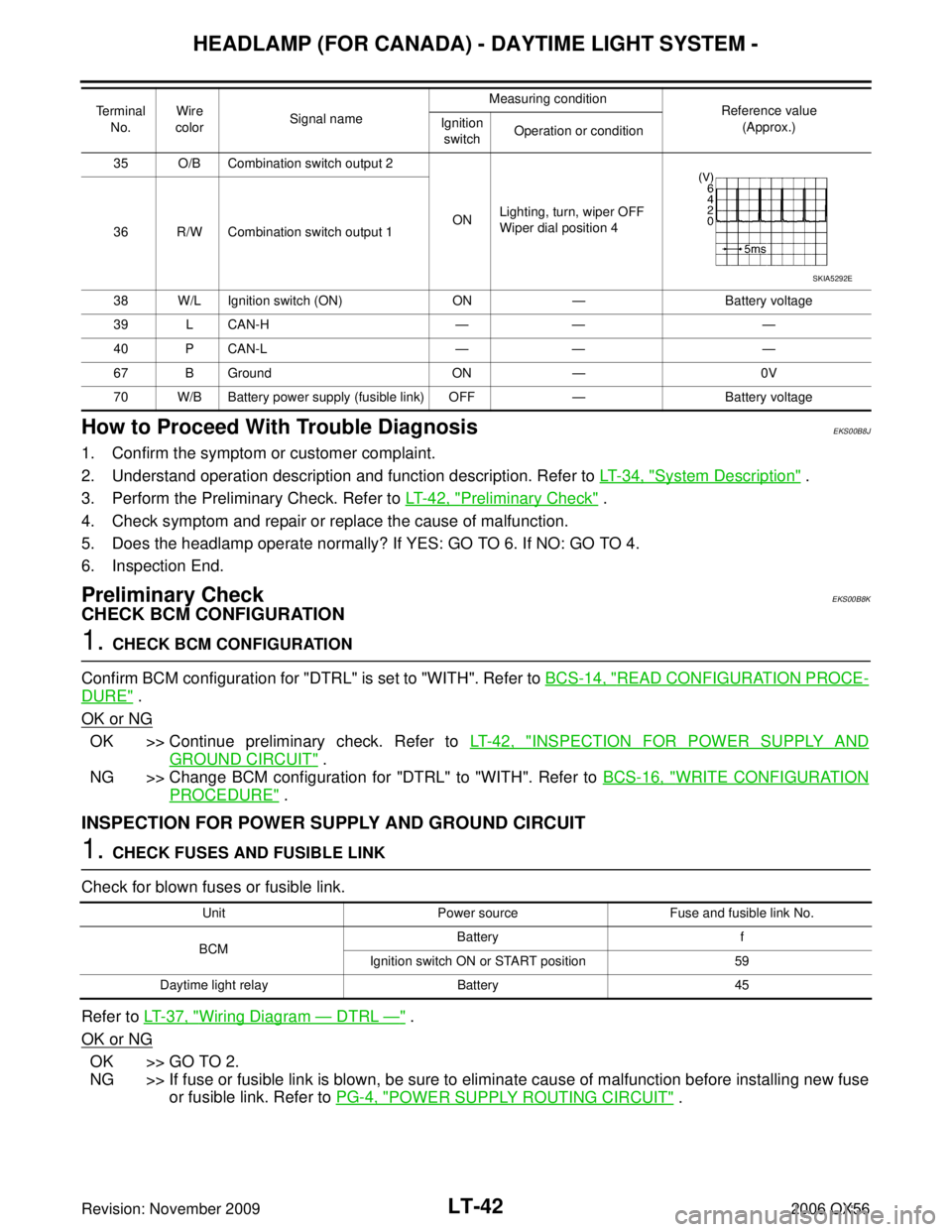
How to Proceed With Trouble DiagnosisEKS00B8J
1. Confirm the symptom or customer complaint.
2. Understand operation description and function description. Refer to LT- 3 4 , "
System Description" .
3. Perform the Preliminary Check. Refer to LT- 4 2 , "
Preliminary Check" .
4. Check symptom and repair or replace the cause of malfunction.
5. Does the headlamp operate normally? If YES: GO TO 6. If NO: GO TO 4.
6. Inspection End.
Preliminary CheckEKS00B8K
CHECK BCM CONFIGURATION
1. CHECK BCM CONFIGURATION
Confirm BCM configuration for "DTRL" is set to "WITH". Refer to BCS-14, "
READ CONFIGURATION PROCE-
DURE" .
OK or NG
OK >> Continue preliminary check. Refer to LT- 4 2 , "INSPECTION FOR POWER SUPPLY AND
GROUND CIRCUIT" .
NG >> Change BCM configuration for "DTRL" to "WITH". Refer to BCS-16, "
WRITE CONFIGURATION
PROCEDURE" .
INSPECTION FOR POWER SUPPLY AND GROUND CIRCUIT
1. CHECK FUSES AND FUSIBLE LINK
Check for blown fuses or fusible link.
Refer to LT- 3 7 , "
Wiring Diagram — DTRL —" .
OK or NG
OK >> GO TO 2.
NG >> If fuse or fusible link is blown, be sure to eliminate cause of malfunction before installing new fuse or fusible link. Refer to PG-4, "
POWER SUPPLY ROUTING CIRCUIT" .
35 O/B Combination switch output 2
ONLighting, turn, wiper OFF
Wiper dial position 4
36 R/W Combination switch output 1
38 W/L Ignition switch (ON) ON— Battery voltage
39 L CAN-H ———
40 P CAN-L ———
67 B Ground ON— 0V
70 W/B Battery power supply (fusible link) OFF —Battery voltage
Terminal
No. Wire
color Signal name Measuring condition
Reference value
(Approx.)
Ignition
switch Operation or condition
SKIA5292E
Unit
Power sourceFuse and fusible link No.
BCM Battery
f
Ignition switch ON or START position 59
Daytime light relay Battery45
Page 2457 of 3383
LT-50
AUTO LIGHT SYSTEM
Revision: November 20092006 QX56
Wiring Diagram — AUTO/L —EKS00B8W
WKWA3647E
Page 2462 of 3383

AUTO LIGHT SYSTEMLT-55
C
DE
F
G H
I
J
L
M A
B
LT
Revision: November 2009 2006 QX56
1 USA
2 Canada
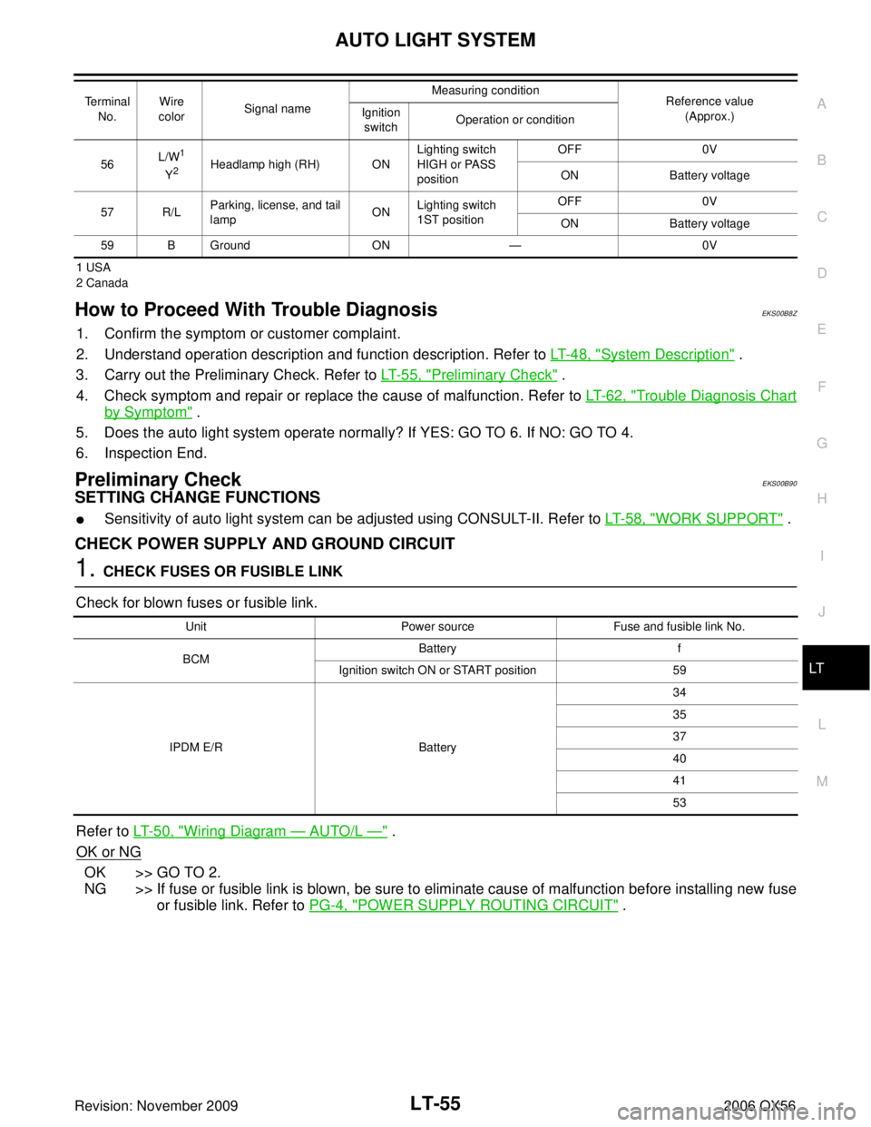
How to Proceed With Trouble DiagnosisEKS00B8Z
1. Confirm the symptom or customer complaint.
2. Understand operation description and function description. Refer to LT- 4 8 , "
System Description" .
3. Carry out the Preliminary Check. Refer to LT- 5 5 , "
Preliminary Check" .
4. Check symptom and repair or replace the cause of malfunction. Refer to LT- 6 2 , "
Trouble Diagnosis Chart
by Symptom" .
5. Does the auto light system operate normally? If YES: GO TO 6. If NO: GO TO 4.
6. Inspection End.
Preliminary CheckEKS00B90
SETTING CHANGE FUNCTIONS
�Sensitivity of auto light system can be adjusted using CONSULT-II. Refer to LT- 5 8 , "WORK SUPPORT" .
CHECK POWER SUPPLY AND GROUND CIRCUIT
1. CHECK FUSES OR FUSIBLE LINK
Check for blown fuses or fusible link.
Refer to LT- 5 0 , "
Wiring Diagram — AUTO/L —" .
OK or NG
OK >> GO TO 2.
NG >> If fuse or fusible link is blown, be sure to eliminate cause of malfunction before installing new fuse or fusible link. Refer to PG-4, "
POWER SUPPLY ROUTING CIRCUIT" .
56L/W1
Y2Headlamp high (RH) ON Lighting switch
HIGH or PASS
positionOFF
0V
ON Battery voltage
57 R/L Parking, license, and tail
lamp ON
Lighting switch
1ST position OFF
0V
ON Battery voltage
59 B Ground ON— 0V
Te r m i n a l
No. Wire
color Signal name Measuring condition
Reference value
(Approx.)
Ignition
switch Operation or condition
Unit
Power sourceFuse and fusible link No.
BCM Battery
f
Ignition switch ON or START position 59
IPDM E/R Battery 34
35
37
40
41
53
Page 2473 of 3383
LT-66
HEADLAMP AIMING CONTROL
Revision: November 20092006 QX56
Wiring Diagram — H/AIM —EKS00B98
WKWA3650E
Page 2478 of 3383
FRONT FOG LAMPLT-71
C
DE
F
G H
I
J
L
M A
B
LT
Revision: November 2009 2006 QX56
Wiring Diagram — F/FOG —EKS00B9E
WKWA3652E
Page 2482 of 3383

FRONT FOG LAMPLT-75
C
DE
F
G H
I
J
L
M A
B
LT
Revision: November 2009 2006 QX56
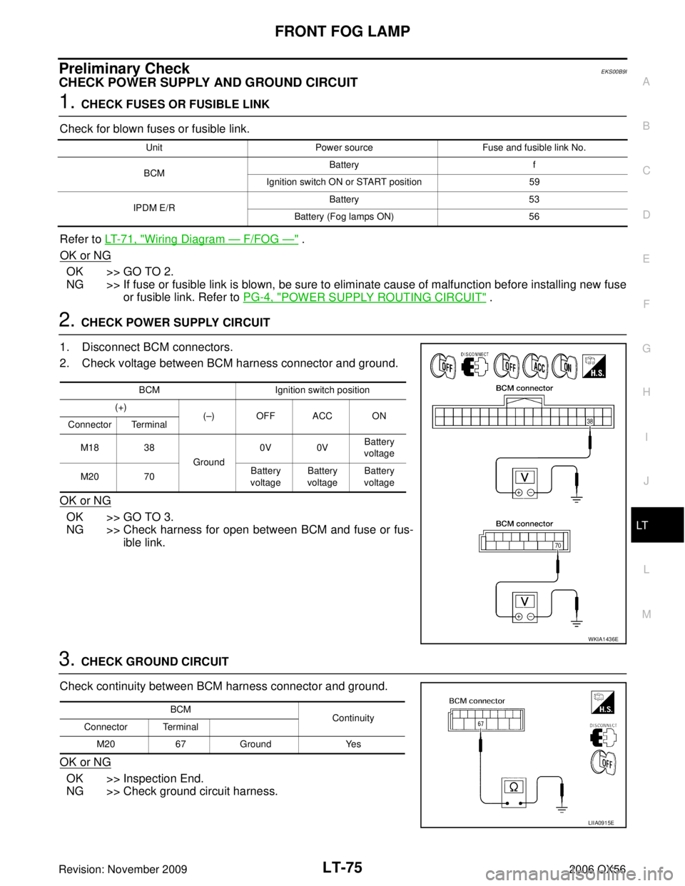
Preliminary CheckEKS00B9I
CHECK POWER SUPPLY AND GROUND CIRCUIT
1. CHECK FUSES OR FUSIBLE LINK
Check for blown fuses or fusible link.
Refer to LT- 7 1 , "
Wiring Diagram — F/FOG —" .
OK or NG
OK >> GO TO 2.
NG >> If fuse or fusible link is blown, be sure to eliminate cause of malfunction before installing new fuse or fusible link. Refer to PG-4, "
POWER SUPPLY ROUTING CIRCUIT" .
2. CHECK POWER SUPPLY CIRCUIT
1. Disconnect BCM connectors.
2. Check voltage between BCM harness connector and ground.
OK or NG
OK >> GO TO 3.
NG >> Check harness for open between BCM and fuse or fus- ible link.
3. CHECK GROUND CIRCUIT
Check continuity between BCM harness connector and ground.
OK or NG
OK >> Inspection End.
NG >> Check ground circuit harness.
Unit Power sourceFuse and fusible link No.
BCM Battery
f
Ignition switch ON or START position 59
IPDM E/R Battery
53
Battery (Fog lamps ON) 56
BCMIgnition switch position
(+) (– )OFFACCON
Connector Terminal
M18 38 Ground0V 0V
Battery
voltage
M20 70 Battery
voltage Battery
voltage Battery
voltage
WKIA1436E
BCM Continuity
Connector Terminal
M20 67Ground Yes
LIIA0915E
Page 2491 of 3383
LT-84
TURN SIGNAL AND HAZARD WARNING LAMPS
Revision: November 20092006 QX56
Wiring Diagram — TURN —EKS00B9S
WKWA3655E