Page 2873 of 3383

RSU-34
REAR SUSPENSION MEMBER
Revision: November 20092006 QX56
INSTALLATION
Installation is in the reverse order of removal.
�When raising the rear suspension member assembly, use the
locating pins to align the rear suspension member to the vehicle
body.
�When installing the upper and lower rubber seats for the rear
coil springs, the arrow embossed on the rubber seats must point
out toward the wheel and tire assembly.
�To connect the rear load leveling air suspension hoses, the lock
ring must be fully seated in the fitting. Insert the hose “B” into the
lock ring “A” until the lock ring “A” is touching the hose “B” as
shown. Pull on the hose to check that it is securely inserted.
�Perform the final tightening of the nuts and bolts for the links (rubber bushing) under unladen condition
(unladen condition means that the fuel tank, engine coolant and lubricants are at the full specification, and
the spare tire, jack, hand tools, and mats are in their designated positions) with the tires on level ground.
�Check the wheel alignment. Refer to RSU-48, "Wheel Alignment" .
LEIA0083E
LEIA0076E
LEIA0078E
Page 2876 of 3383
SUSPENSION ARMRSU-37
C
DF
G H
I
J
K L
M A
B
RSU
Revision: November 2009 2006 QX56
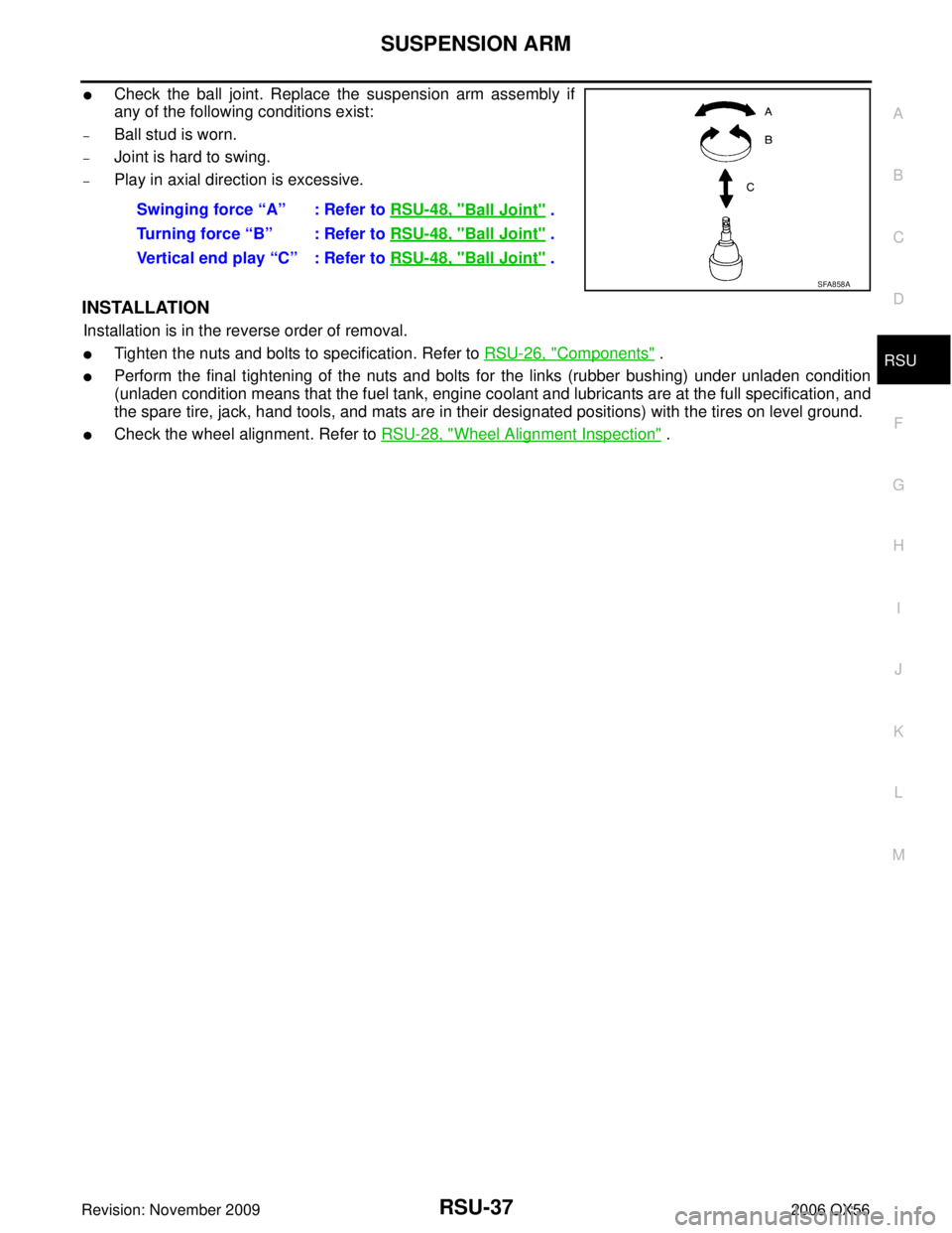
�Check the ball joint. Replace the suspension arm assembly if
any of the following conditions exist:
–Ball stud is worn.
–Joint is hard to swing.
–Play in axial direction is excessive.
INSTALLATION
Installation is in the reverse order of removal.
�Tighten the nuts and bolts to specification. Refer to RSU-26, "Components" .
�Perform the final tightening of the nuts and bolts for the links (rubber bushing) under unladen condition
(unladen condition means that the fuel tank, engine coolant and lubricants are at the full specification, and
the spare tire, jack, hand tools, and mats are in their designated positions) with the tires on level ground.
�Check the wheel alignment. Refer to RSU-28, "Wheel Alignment Inspection" .
Swinging force “A” : Refer to
RSU-48, "
Ball Joint" .
Turning force “B” : Refer to RSU-48, "
Ball Joint" .
Vertical end play “C” : Refer to RSU-48, "
Ball Joint" .
SFA858A
Page 2878 of 3383
FRONT LOWER LINKRSU-39
C
DF
G H
I
J
K L
M A
B
RSU
Revision: November 2009 2006 QX56
INSTALLATION
Installation is in the reverse order of removal.
�Tighten the nuts and bolts to specification. Refer to RSU-26, "Components" .
�Perform the final tightening of the nuts and bolts for the links (rubber bushing) under unladen condition
(unladen condition means that the fuel tank, engine coolant and lubricants are at the full specification, and
the spare tire, jack, hand tools, and mats are in their designated positions) with the tires on level ground.
�Check the wheel alignment. Refer to RSU-28, "Wheel Alignment Inspection" .
Page 2888 of 3383
SERVICE DATA AND SPECIFICATIONS (SDS)RSU-49
C
DF
G H
I
J
K L
M A
B
RSU
Revision: November 2009 2006 QX56
Wheelarch Height (Unladen*1 )EES001HV
Unit: mm (in)
*1: Fuel, engine coolant and engine oil full. Spare tire, jack, hand tools and mats in designated positions.
*2: Verify the vehicle height. If vehicle height is not within ± 10 mm (0.39 in) of the specification, perform the control unit initialization pro-
cedure. Refer to RSU-47, "
Initialization Procedure" .
Suspension type
Air leveling*
2
Applied model2WD 4WD
Front wheelarch height (Hf) 913
(35.94) 931
(36.65)
Rear wheelarch height (Hr) 912
(35.91) 932
(36.69)
LEIA0085E
Page 3296 of 3383
, install
two balance weight sheets in line with eac")
WHEEL AND TIRE ASSEMBLYWT-7
C
DF
G H
I
J
K L
M A
B
WT
Revision: November 2009 2006 QX56
c. If calculated balance weight value exceeds 50 g (1.76 oz), install
two balance weight sheets in line with each other as shown.
CAUTION:
Do not install one balance weight sheet on top of another.
3. Start wheel balancer again.
4. Install drive-in balance weight on inner side of road wheel in the wheel balancer indication position (angle).
CAUTION:
Do not install more than two balance weights.
5. Start wheel balancer. Make sure that inner and outer residual imbalance values are 5 g (0.18 oz) each or below.
�If either residual imbalance value exceeds 5 g (0.18 oz), repeat installation procedures.
Wheel balance (Maximum allowable imbalance):
RotationEES001Q1
NOTE:
Follow the maintenance schedule for tire rotation service intervals. Refer to MA-7, "
PERIODIC MAINTE-
NANCE" .
1. Rotate the tires on each side from front to back as shown. Do not include the spare tire when rotating the tires.
CAUTION:
When installing wheels, tighten them diagonally by dividing
the work two to three times in order to prevent the wheels
from developing any distortion.
2. Adjust the tire pressure to specification. Refer to WT-38, "
Tire" .
3. After the tire rotation, retighten the wheel nuts after the vehicle has been driven for 1,000 km (600 miles), and also after every
wheel and tire have been installed such as after repairing a flat
tire.
Maximum allowable imbalance Dynamic (At rim flange)
5 g (0.18 oz) (one side)
Static 10 g (0.35 oz)
SMA056D
Wheel nut torque : 133 N·m (14 kg-m, 98 ft-lb)
SMA829C
Page 3327 of 3383
WT-38
SERVICE DATA AND SPECIFICATIONS (SDS)
Revision: November 20092006 QX56
SERVICE DATA AND SPECIFICATIONS (SDS)PFP:00030
Road WheelEES001IO
TireEES001IP
Unit: kPa (kg/cm2 , psi)
Wheel type
Aluminum
Maximum radial runout limit Lateral mm (in)
0.3 (0.012) or less
Radial mm (in) 0.3 (0.012) or less
Maximum residual imbalance Dynamic (at rim flange)
Less than 5 g (0.18 oz) (per side)
Static (at rim flange) Less than 10 g (0.35 oz)
Tire size Air pressure
Conventional tire Spare tire
Full size spare tire —240 (2.4, 35)
P265/70R18 240 (2.4, 35)—
Page:
< prev 1-8 9-16 17-24
RSU-49
C
DF
G H
I
J
K L
M A
B
RSU
Revision: November 2009 2006 QX56
Wheelarch Height (Unladen*1 )EES001HV
Unit: mm (in)
*1: Fuel, engine coolant and engine oil ful")

Revision: November 20092006 QX56
SERVICE DATA AND SPECIFICATIONS (SDS)PFP:00030
Road WheelEES001IO
TireEES001IP
Unit: kPa (kg/cm2 , psi)
Wheel type
Aluminum")