Page 3254 of 3383
TRANSFER ASSEMBLYTF-149
CE F
G H
I
J
K L
M A
B
TF
Revision: November 2009 2006 QX56
Front Case
1. Remove the rear case assembly. Refer to TF-148, "Rear Case" .
2. Remove the lock pin nut.
3. Remove the lock pin using suitable tool.
4. Remove the shift lever.
5. Remove the side oil seal from the front case using suitable tool. CAUTION:
Do not damage front case or shift cross.
6. Remove the check plug, check spring and check ball.
7. Remove the wait detection switch.
8. Remove the self-lock nut from the companion flange using Tool.
SDIA2150E
SDIA3381E
WDIA0196E
Tool number : KV40104000 ( — )
SDIA2841E
Page 3263 of 3383
TF-158
TRANSFER ASSEMBLY
Revision: November 20092006 QX56
21. Remove the snap ring from the mainshaft.
22. Remove the mainshaft from the clutch drum and clutch hub
using suitable tool.
23. Remove the needle bearing and spacer from the mainshaft.
24. Remove the snap ring from the clutch hub using suitable tool.
25. Remove the oil pressure check plug from the oil pressure check port.
26. Apply air gradually from the oil pressure check port, and remove the clutch piston assembly from the center case.
SDIA2113E
SMT914C
WDIA0101E
SDIA3188E
SDIA2116E
Page 3268 of 3383
TRANSFER ASSEMBLYTF-163
CE F
G H
I
J
K L
M A
B
TF
Revision: November 2009 2006 QX56
42. Remove the O-rings (1) from the oil filter (2).
43. Remove the oil filter stud from the oil filter.
44. Remove the O-ring from the oil filter stud.
INSPECTION AFTER DISASSEMBLY
Shift Rod Components
�Check the working face of the shift rod and fork for wear, partial
wear, bending and other abnormality. If any is found, replace
with a new one.
�Measure the clearance between the shift fork and sleeve. If it is
out of specification, replace it with a new one.
WDIA0285E
SDIA3180E
SMT009D
Specification : Less than 0.36 mm (0.0142 in)
SMT010D
Page 3269 of 3383

TF-164
TRANSFER ASSEMBLY
Revision: November 20092006 QX56
Planetary Carrier
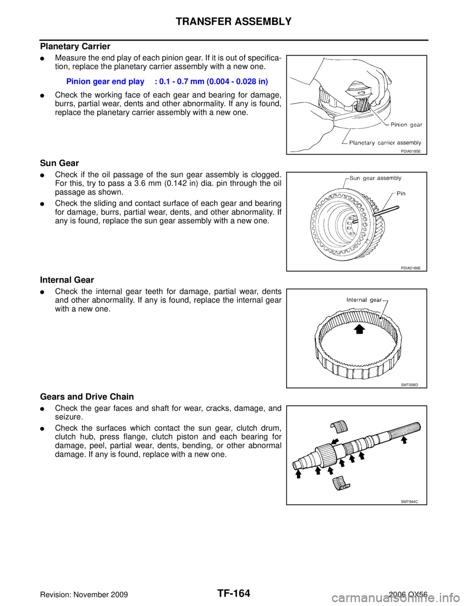
�Measure the end play of each pinion gear. If it is out of specifica-
tion, replace the planetary carrier assembly with a new one.
�Check the working face of each gear and bearing for damage,
burrs, partial wear, dents and other abnormality. If any is found,
replace the planetary carrier assembly with a new one.
Sun Gear
�Check if the oil passage of the sun gear assembly is clogged.
For this, try to pass a 3.6 mm (0.142 in) dia. pin through the oil
passage as shown.
�Check the sliding and contact surface of each gear and bearing
for damage, burrs, partial wear, dents, and other abnormality. If
any is found, replace the sun gear assembly with a new one.
Internal Gear
�Check the internal gear teeth for damage, partial wear, dents
and other abnormality. If any is found, replace the internal gear
with a new one.
Gears and Drive Chain
�Check the gear faces and shaft for wear, cracks, damage, and
seizure.
�Check the surfaces which contact the sun gear, clutch drum,
clutch hub, press flange, clutch piston and each bearing for
damage, peel, partial wear, dents, bending, or other abnormal
damage. If any is found, replace with a new one.Pinion gear end play : 0.1 - 0.7 mm (0.004 - 0.028 in)
PDIA0185E
PDIA0186E
SMT008D
SMT944C
Page 3270 of 3383

TRANSFER ASSEMBLYTF-165
CE F
G H
I
J
K L
M A
B
TF
Revision: November 2009 2006 QX56
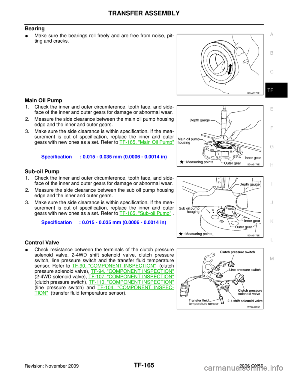
Bearing
�Make sure the bearings roll freely and are free from noise, pit-
ting and cracks.
Main Oil Pump
1. Check the inner and outer circumference, tooth face, and side-
face of the inner and outer gears for damage or abnormal wear.
2. Measure the side clearance between the main oil pump housing edge and the inner and outer gears.
3. Make sure the side clearance is within specification. If the mea- surement is out of specification, replace the inner and outer
gears with new ones as a set. Refer to TF-165, "
Main Oil Pump"
.
Sub-oil Pump
1. Check the inner and outer circumference, tooth face, and side-
face of the inner and outer gears for damage or abnormal wear.
2. Measure the side clearance between the sub oil pump housing edge and the inner and outer gears.
3. Make sure the side clearance is within specification. If the mea- surement is out of specification, replace the inner and outer
gears with new ones as a set. Refer to TF-165, "
Sub-oil Pump" .
Control Valve
�Check resistance between the terminals of the clutch pressure
solenoid valve, 2-4WD shift solenoid valve, clutch pressure
switch, line pressure switch and the transfer fluid temperature
sensor. Refer to TF-90, "
COMPONENT INSPECTION" (clutch
pressure solenoid valve), TF-94, "
COMPONENT INSPECTION"
(2-4WD solenoid valve), TF-107, "COMPONENT INSPECTION"
(clutch pressure switch), TF-110, "COMPONENT INSPECTION"
(line pressure switch) and TF-104, "COMPONENT INSPEC-
TION" (transfer fluid temperature sensor).
SDIA2175E
Specification : 0.015 - 0.035 mm (0.0006 - 0.0014 in)
SDIA2174E
Specification : 0.015 - 0.035 mm (0.0006 - 0.0014 in)
SDIA2173E
WDIA0199E
Page 3276 of 3383

TRANSFER ASSEMBLYTF-171
CE F
G H
I
J
K L
M A
B
TF
Revision: November 2009 2006 QX56
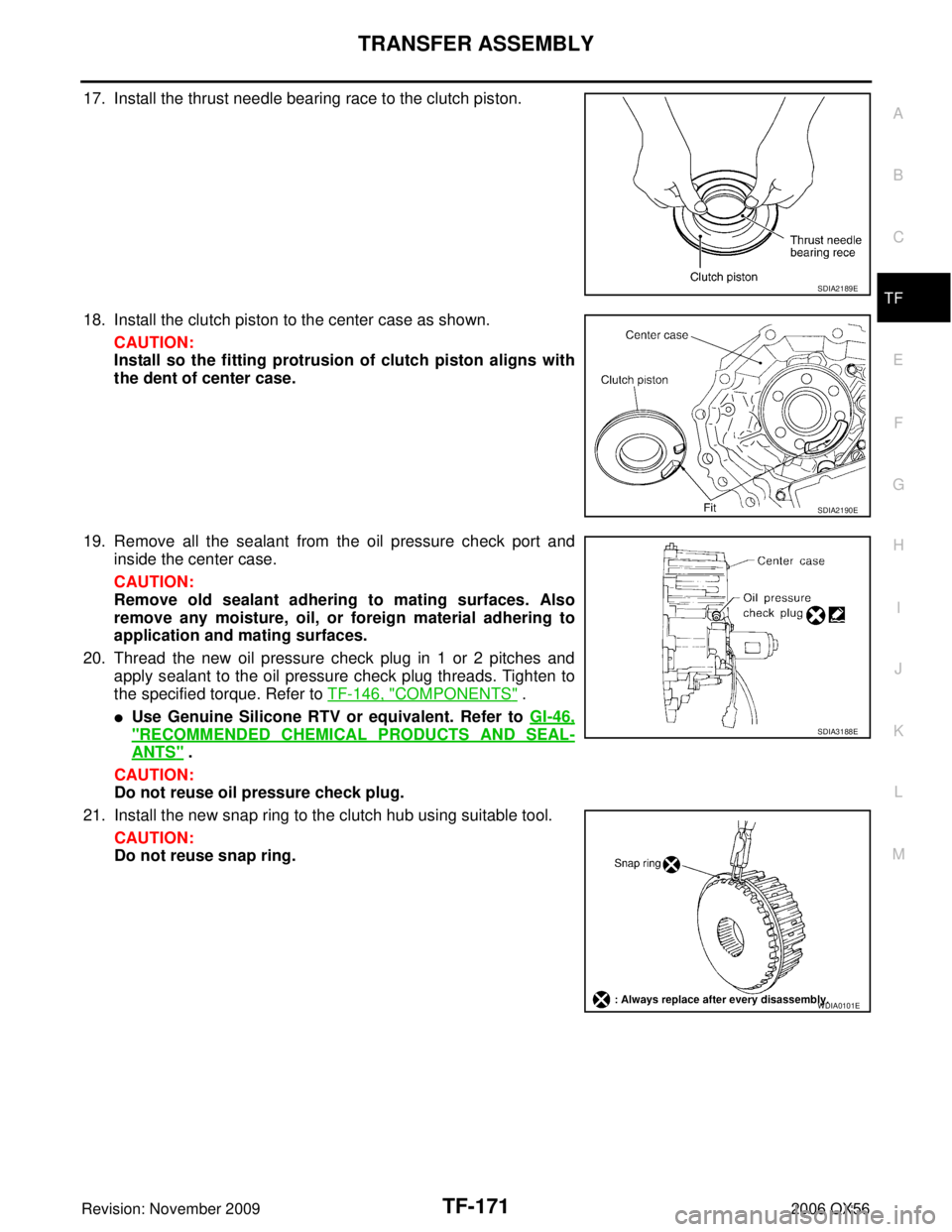
17. Install the thrust needle bearing race to the clutch piston.
18. Install the clutch piston to the center case as shown.
CAUTION:
Install so the fitting protrusion of clutch piston aligns with
the dent of center case.
19. Remove all the sealant from the oil pressure check port and inside the center case.
CAUTION:
Remove old sealant adhering to mating surfaces. Also
remove any moisture, oil, or foreign material adhering to
application and mating surfaces.
20. Thread the new oil pressure check plug in 1 or 2 pitches and apply sealant to the oil pressure check plug threads. Tighten to
the specified torque. Refer to TF-146, "
COMPONENTS" .
�Use Genuine Silicone RTV or equivalent. Refer to GI-46,
"RECOMMENDED CHEMICAL PRODUCTS AND SEAL-
ANTS" .
CAUTION:
Do not reuse oil pressure check plug.
21. Install the new snap ring to the clutch hub using suitable tool. CAUTION:
Do not reuse snap ring.
SDIA2189E
SDIA2190E
SDIA3188E
WDIA0101E
Page 3286 of 3383

TRANSFER ASSEMBLYTF-181
CE F
G H
I
J
K L
M A
B
TF
Revision: November 2009 2006 QX56
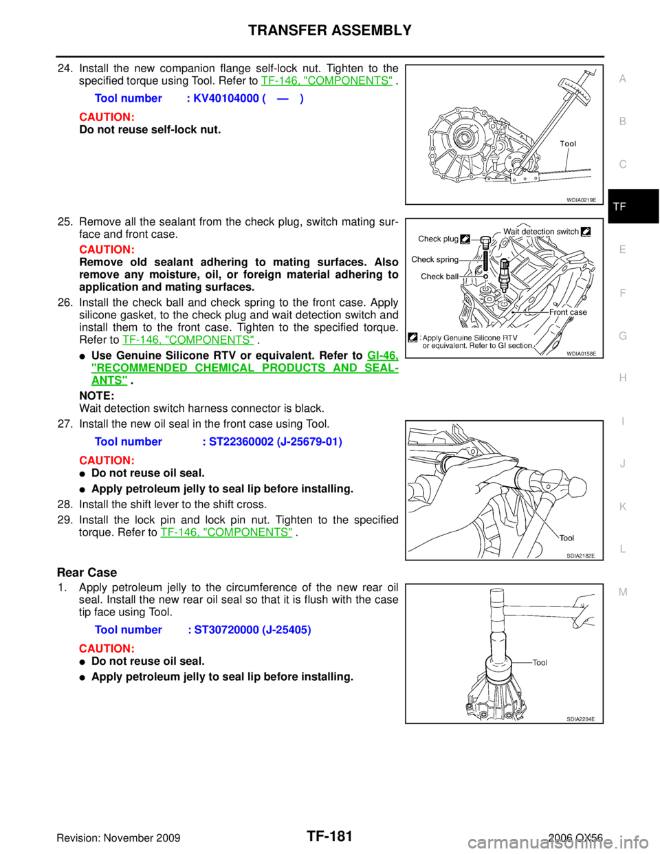
24. Install the new companion flange self-lock nut. Tighten to the
specified torque using Tool. Refer to TF-146, "
COMPONENTS" .
CAUTION:
Do not reuse self-lock nut.
25. Remove all the sealant from the check plug, switch mating sur- face and front case.
CAUTION:
Remove old sealant adhering to mating surfaces. Also
remove any moisture, oil, or foreign material adhering to
application and mating surfaces.
26. Install the check ball and check spring to the front case. Apply silicone gasket, to the check plug and wait detection switch and
install them to the front case. Tighten to the specified torque.
Refer to TF-146, "
COMPONENTS" .
�Use Genuine Silicone RTV or equivalent. Refer to GI-46,
"RECOMMENDED CHEMICAL PRODUCTS AND SEAL-
ANTS" .
NOTE:
Wait detection switch harness connector is black.
27. Install the new oil seal in the front case using Tool.
CAUTION:
�Do not reuse oil seal.
�Apply petroleum jelly to seal lip before installing.
28. Install the shift lever to the shift cross.
29. Install the lock pin and lock pin nut. Tighten to the specified torque. Refer to TF-146, "
COMPONENTS" .
Rear Case
1. Apply petroleum jelly to the circumference of the new rear oil
seal. Install the new rear oil seal so that it is flush with the case
tip face using Tool.
CAUTION:
�Do not reuse oil seal.
�Apply petroleum jelly to seal lip before installing.Tool number : KV40104000 ( — )
WDIA0219E
Tool number : ST22360002 (J-25679-01)
WDIA0158E
SDIA2182E
Tool number : ST30720000 (J-25405)
SDIA2204E
Page 3288 of 3383

SERVICE DATA AND SPECIFICATIONS (SDS)TF-183
CE F
G H
I
J
K L
M A
B
TF
Revision: November 2009 2006 QX56
SERVICE DATA AND SPECIFICATIONS (SDS)PFP:00030
General SpecificationsEDS003BH
Inspection and AdjustmentEDS003BI
CLEARANCE BETWEEN INNER GEAR AND OUTER GEAR
Unit: mm (in)
CLUTCH
Unit: mm (in)
PINION GEAR END PLAY
Unit: mm (in)
CLEARANCE BETWEEN SHIFT FORK AND SLEEVE
Unit: mm (in)
SELECTIVE PARTS
Sub-oil Pump
Unit: mm (in)
*: Always check with the Parts Department for the latest parts information. Applied model
VK56DE
Transfer model ATX14B
Fluid capacity (Approx.) (US qt, lmp qt) 3.0 (3-1/8, 2-5/8)
Gear ratio High
1.000
Low 2.596
Number of teeth Sun gear
57
Internal gear 91
Front drive sprocket 38
Front drive shaft 38
ItemSpecification
Main oil pump 0.015 - 0.035 (0.0006 - 0.0014)
Sub-oil pump 0.015 - 0.035 (0.0006 - 0.0014)
ItemLimit value
Drive plate 1.4 (0.055)
ItemStandard
Pinion gear end play 0.1 - 0.7 (0.004 - 0.028)
ItemStandard
Shift fork and sleeve Less than 0.36 (0.0142)
Gear thicknessPart number*
Inner gear Outer gear
9.27 - 9.28 (0.3650 - 0.3654) 31346 0W46231347 0W462
9.28 - 9.29 (0.3654 - 0.3657) 31346 0W46131347 0W461
9.29 - 9.30 (0.3657 - 0.3661) 31346 0W46031347 0W460