Page 2757 of 3383
PS-24
HYDRAULIC LINE
Revision: November 20092006 QX56
Installation is in the reverse order of removal.
�Confirm mating marks are aligned with hose and clamp, then
correct if needed.
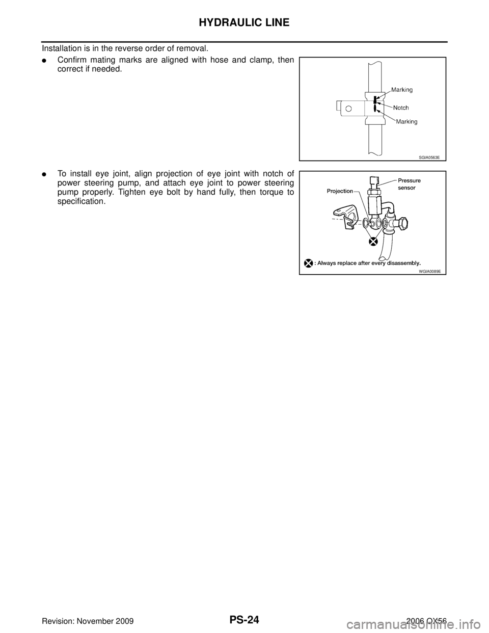
�To install eye joint, align projection of eye joint with notch of
power steering pump, and attach eye joint to power steering
pump properly. Tighten eye bolt by hand fully, then torque to
specification.
SGIA0563E
WGIA0089E
Page 2758 of 3383
SERVICE DATA AND SPECIFICATIONS (SDS)PS-25
C
DE
F
H I
J
K L
M A
B
PS
Revision: November 2009 2006 QX56
SERVICE DATA AND SPECIFICATIONS (SDS)PFP:00030
Steering WheelEGS000UN
Steering ColumnEGS000UO
Inspection After Assembly
Unit: mm (in)
Inspection After Removal
Unit: mm (in)
End play of the axial direction for steering wheel
0 mm (0 in)
Steering wheel play on the outer circumference 0 − 35 mm (0 − 1.38 in)
Steering wheel turning force 39 N (4 kg-f, 9 lb-f) or less
Steering column length “L” 610 (24.02)
WGIA0080E
Steering column length “L2” 262 (10.31)
Steering column length “ L1” 158 (6.22)
SGIA0475E
Page 2759 of 3383
PS-26
SERVICE DATA AND SPECIFICATIONS (SDS)
Revision: November 20092006 QX56
Inspection After Installation
Steering Outer Socket and Inner SocketEGS000UP
Unit: mm (in)
Range
“A ” 61.3 mm (2.41 in)
WGIA0083E
Tie-rod ball joint outer socketSwinging torque
0.3 − 2.9 N ·m (0.03 − 0.29 kg-m, 3 − 25 in-lb)
Measurement on spring balance�Measuring point: cotter pin hole of stud 4.84
− 46.7 N (0.50 − 4.7 kg, 4 − 34 lb)
Rotating torque 0.3 − 2.9 N ·m (0.03 − 0.29 kg-m, 3 − 25 in-lb)
Axial end play 0.5 mm (0.020 in) or less
Tie-rod ball joint inner socket Swinging torque
1.0 − 7.8 N ·m (0.11 − 0.79 kg-m, 9 − 69 in-lb)
Measurement on spring balance
�Measuring point: "L" mark see above,
"L"=83.2 mm (3.276 in). 12.1
− 93.7 N (1.3 − 9.5 kg, 9 − 69 lb)
Axial end play 0.2 mm (0.08 in) or less
SGIA0358E
Inner socket length “L ” 115.2 (4.54)
SGIA0167E
Page 2760 of 3383
SERVICE DATA AND SPECIFICATIONS (SDS)PS-27
C
DE
F
H I
J
K L
M A
B
PS
Revision: November 2009 2006 QX56
Steering GearEGS000UQ
Oil PumpEGS000UR
Steering FluidEGS000US
Steering gear modelPR26AM
Rack neutral position, dimension “L ” (rack stroke) 85.5 mm (3.36 in)
Rack sliding force At the neutral point:
Range within ±
11.5 mm
( ± 0.453 in) from the neutral
position
(in power ON) Area average value 250.1
− 308.9 N (25.5 − 31.5 kg, 56.2 − 69.5 lb)
Area minimum value 200 N (20.4 kg, 45 lb)
Allowable variation 98 N (10 kg, 22 lb) or less
STC0034D
Relief oil pressure
9.0 − 9.8 mPa (91.77 − 99.93 kg/cm2 , 1305.34 − 1421.37 psi)
Fluid capacity
Approx. 1.0 (1-1/8 US qt, 7/8 Imp qt)
Page 2765 of 3383
 TROUBLESHOOTING
Revision: November 20092006 QX56
NOISE, VIBRATION, AND HARSHNESS (NVH) TROUBLESHOOTINGPFP:00003
NVH Troubleshooting ChartEDS001XM
Use chart")
RAX-4
NOISE, VIBRATION, AND HARSHNESS (NVH) TROUBLESHOOTING
Revision: November 20092006 QX56
NOISE, VIBRATION, AND HARSHNESS (NVH) TROUBLESHOOTINGPFP:00003
NVH Troubleshooting ChartEDS001XM
Use chart below to help you find the cause of the symptom. If necessary, repair or replace these parts.
×: ApplicableReference page
—
RAX-8—
RAX-5—
RFD-7, "
NVH Troubleshooting Chart
"
FAX-4, "
NVH Troubleshooting Chart
" (FAX), FSU-4, "
NVH Troubleshooting Chart
" (FSU)
RSU-5, "
NVH Troubleshooting Chart
"
WT-4, "
NVH Troubleshooting Chart
"
WT-4, "
NVH Troubleshooting Chart
"
PR-3, "
NVH Troubleshooting Chart
"
BR-5, "
NVH Troubleshooting Chart
"
PS-5, "
NVH Troubleshooting Chart
"
Possible cause and SUSPECTED PARTS
Excessive joint angle
Joint sliding resistance
Imbalance
Improper installation, looseness
Parts interference
DIFFERENTIAL
FRONT AXLE AND FRONT SUSPENSION
REAR SUSPENSION
TIRES
ROAD WHEEL
PROPELLER SHAFT
BRAKES
STEERING
Symptom Noise
×× ×× ×× ×××××
Shake × × ×× × ×××××
Vibration ×× ×× × × × ×
Shimmy ×× ×××××
Shudder × × ×× ××
Poor quality ride or handling ×× ×× ×× ×
Page 2812 of 3383
NOISE, VIBRATION, AND HARSHNESS (NVH) TROUBLESHOOTINGRFD-7
CE F
G H
I
J
K L
M A
B
RFD
Revision: November 2009 2006 QX56
NOISE, VIBRATION, AND HARSHNESS (NVH) TROUBLESHOOTINGPFP:00003
NVH Troubleshooting ChartEDS0044N
Use the chart below to help you find the cause of the symptom. If necessary, repair or replace these parts.
×: Applicable
Reference page
RFD-23RFD-17RFD-17RFD-18RFD-18RFD-8
PR-3, "
NVH Troubleshooting Chart
"
RAX-4, "
NVH Troubleshooting Chart
"
RSU-5, "
NVH Troubleshooting Chart
"
WT-4, "
NVH Troubleshooting Chart
"
WT-4, "
NVH Troubleshooting Chart
"
FAX-4, "
NVH Troubleshooting Chart
"
BR-5, "
NVH Troubleshooting Chart
"
PS-5, "
NVH Troubleshooting Chart
"
Possible cause and SUSPECTED PARTS
Gear tooth rough
Gear contact improper
Tooth surfaces worn
Backlash incorrect
Companion flange excessive runout
Gear oil improper
PROPELLER SHAFT
REAR AXLE
REAR SUSPENSION
TIRES
ROAD WHEEL
DRIVE SHAFT
BRAKES
STEERING
Symptom FINAL DRIVE Noise ××××××××××××××
Page 2844 of 3383
 TROUBLESHOOTINGRSU-5
C
DF
G H
I
J
K L
M A
B
RSU
Revision: November 2009 2006 QX56
NOISE, VIBRATION, AND HARSHNESS (NVH) TROUBLESHOOTINGPFP:00003
NVH Troubleshooti")
NOISE, VIBRATION, AND HARSHNESS (NVH) TROUBLESHOOTINGRSU-5
C
DF
G H
I
J
K L
M A
B
RSU
Revision: November 2009 2006 QX56
NOISE, VIBRATION, AND HARSHNESS (NVH) TROUBLESHOOTINGPFP:00003
NVH Troubleshooting ChartEES001H1
Use chart below to help you find the cause of the symptom. If necessary, repair or replace these parts.
×: ApplicableReference page
RSU-26RSU-35
—
—
—
RSU-26
RSU-28RSU-42
PR-3, "
NVH Troubleshooting Chart
"
RFD-7, "
NVH Troubleshooting Chart
"
FAX-4, "
NVH Troubleshooting Chart
"
FSU-4, "
NVH Troubleshooting Chart
"
WT-4, "
NVH Troubleshooting Chart
"
WT-4, "
NVH Troubleshooting Chart
"
RAX-4, "
NVH Troubleshooting Chart
"
PS-5, "
NVH Troubleshooting Chart
"
BR-5, "
NVH Troubleshooting Chart
"
Possible cause and SUSPECTED PARTS
Improper installation, looseness
Shock absorber deformation, damage or deflection
Bushing or mounting deterioration
Parts interference
Spring fatigue
Suspension looseness
Incorrect wheel alignment
Stabilizer bar fatigue
PROPELLER SHAFT
DIFFERENTIAL
FRONT AXLE
FRONT SUSPENSION
TIRES
ROAD WHEEL
DRIVE SHAFT
BRAKES
STEERING
Symptom Noise
×××××× ××× ××××××
Shake ×××× × × × ××××××
Vibration ××××× × × ×× × ×
Shimmy ×××× × × ××× ××
Shudder ××× × ××× ××
Poor quality ride or handling ××××× ×× × ×××
Page 2867 of 3383

RSU-28
REAR SUSPENSION ASSEMBLY
Revision: November 20092006 QX56
Wheel Alignment InspectionEES001HH
Rear Wheel Alignment Adjusting Bolts
PRELIMINARY INSPECTION
WARNING:
Always adjust the alignment with the vehicle on a flat surface. Use CONSULT-II “EXHAUST SOLE-
NOID” active test to release the air pressure from the rear load leveling air suspension system.
NOTE:
If alignment is out of specification, inspect and replace any damaged or worn rear suspension parts before
making any adjustments.
1. Check and adjust the wheel alignment with the vehicle under unladen conditions. “Unladen conditions”
means that the fuel, coolant, and lubricant are full; and that the spare tire, jack, hand tools and mats are in
their designated positions.
2. Check the tires for incorrect air pressure and excessive wear.
3. Check the wheels for runout and damage. Refer to WT-5, "
Inspection" .
4. Check the wheel bearing axial end play.
5. Check the shock absorbers. Refer to RSU-27, "
SHOCK ABSORBER INSPECTION" .
6. Check each mounting point of the suspension components for any excessive looseness or damage.
7. Check each link, arm, and the rear suspension member for any damage.
8. Check the vehicle height. Refer to RSU-49, "
Wheelarch Height (Unladen*1 )" .
�If vehicle height is not within ± 10 mm (0.39 in) of the specification, perform the control unit initialization
procedure. Refer to RSU-47, "
Initialization Procedure" .
GENERAL INFORMATION AND RECOMMENDATIONS
1. A Four-Wheel Thrust Alignment should be performed.
�This type of alignment is recommended for any NISSAN vehicle.
�The four-wheel “thrust” process helps ensure that the vehicle is properly aligned and the steering wheel
is centered.
�The alignment machine itself should be capable of accepting any NISSAN vehicle.
�The alignment machine should be checked to ensure that it is level.
2. Make sure the alignment machine is properly calibrated.
�Your alignment machine should be regularly calibrated in order to give correct information.
WEIA0102E
1. Rear lower link adjusting bolt, LH 2. Front lower link adjusting bolt, LH 3. Front lower link adjusting bolt, RH
4. Rear lower link adjusting bolt, RH
Axial end play : 0 mm (0 in)
PS-25
C
DE
F
H I
J
K L
M A
B
PS
Revision: November 2009 2006 QX56
SERVICE DATA AND SPECIFICATIONS (SDS)PFP:00030
Steering WheelEGS000UN
Steering ColumnEGS000UO
Ins")

Revision: November 20092006 QX56
Inspection After Installation
Steering Outer Socket and Inner SocketEGS000UP
Unit: mm (in)
Range
“A ” 61.3 mm (2.41 in")
PS-27
C
DE
F
H I
J
K L
M A
B
PS
Revision: November 2009 2006 QX56
Steering GearEGS000UQ
Oil PumpEGS000UR
Steering FluidEGS000US
Steering gear modelPR26AM
Rack neut")
 TROUBLESHOOTINGRFD-7
CE F
G H
I
J
K L
M A
B
RFD
Revision: November 2009 2006 QX56
NOISE, VIBRATION, AND HARSHNESS (NVH) TROUBLESHOOTINGPFP:00003
NVH Troubleshooti")