Page 3139 of 3383

TF-34
TROUBLE DIAGNOSIS
Revision: November 20092006 QX56
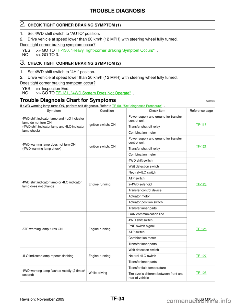
2. CHECK TIGHT CORNER BRAKING SYMPTOM (1)
1. Set 4WD shift switch to “AUTO” position.
2. Drive vehicle at speed lower than 20 km/h (12 MPH) with steering wheel fully turned.
Does tight corner braking symptom occur?
YES >> GO TO TF-130, "Heavy Tight-corner Braking Symptom Occurs" .
NO >> GO TO 3.
3. CHECK TIGHT CORNER BRAKING SYMPTOM (2)
1. Set 4WD shift switch to “4HI” position.
2. Drive vehicle at speed lower than 20 km/h (12 MPH) with steering wheel fully turned.
Does tight corner braking symptom occur?
YES >> Inspection End.
NO >> GO TO TF-131, "
4WD System Does Not Operate" .
Trouble Diagnosis Chart for SymptomsEDS002HI
If 4WD warning lamp turns ON, perform self-diagnosis. Refer to TF-50, "Self-diagnostic Procedure" .
Symptom ConditionCheck itemReference page
4WD shift indicator lamp and 4LO indicator
lamp do not turn ON
(4WD shift indicator lamp and 4LO indicator
lamp check) Ignition switch: ONPower supply and ground for transfer
control unit
TF-117
Transfer shut off relay
Combination meter
4WD warning lamp does not turn ON
(4WD warning lamp check) Ignition switch: ONPower supply and ground for transfer
control unit
TF-121
Transfer shut off relay
Combination meter
4WD shift indicator lamp or 4LO indicator
lamp does not change Engine running4WD shift switch
TF-123
Wait detection switch
Neutral-4LO switch
AT P s w i t c h
2-4WD solenoid
Transfer control device
Actuator motor
Actuator position switch
Transfer inner parts
ATP warning lamp turns ON Engine running CAN communication line
TF-125
4WD shift switch
PNP switch signal
AT P s w i t c h
Combination meter
Transfer inner parts
4LO indicator lamp repeats flashing Engine running Wait detection switch
TF-127
Neutral-4LO switch
Transfer inner parts
4WD warning lamp flashes rapidly (2 times/
second) While drivingTransfer fluid temperature
TF-128
Tire size is different between front and
rear of vehicle
Page 3140 of 3383

TROUBLE DIAGNOSISTF-35
CE F
G H
I
J
K L
M A
B
TF
Revision: November 2009 2006 QX56
NOTE:
�Light tight-corner braking symptom may occur depending on driving conditions in AUTO mode. This is not
a malfunction.
�Heavy tight-corner braking symptom occurs when vehicle is driven in the following conditions: 4WD shift
switch is "4H" or "4LO", steering wheel is turned fully to either side.
Transfer Control Unit Input/Output Signal Reference ValuesEDS002HJ
TRANSFER CONTROL UNIT INSPECTION TABLE
Specifications with CONSULT-II
4WD warning lamp flashes slowly
(1 time/2 seconds)While drivingTire size is different between front and
rear of vehicle.
TF-129
Transfer fluid temperature
Clutch pressure switch
Heavy tight-corner braking symptom occurs
(See NOTE.)
�While driving
�AUTO mode
�Steering wheel is
turned fully to either
side CAN communication line
TF-130
4WD shift switch
Accelerator pedal position signal
Clutch pressure solenoid
Transfer inner parts
4WD system does not operate While driving 4WD shift switch
TF-131
Clutch pressure switch
Transfer inner parts
Symptom
ConditionCheck itemReference page
Monitored item [Unit] Content ConditionDisplay value
VHCL/S SEN ·FR [km/h]
or [mph] Front wheel speed Vehicle stopped
0 km/h (0 MPH)
Vehicle running
CAUTION:
Check air pressure of tire under standard condition. Approximately
equal to the indi-
cation on speed-
ometer (Inside of
±
10%)
VHCL/S SEN ·RR [km/h]
or [mph] Rear wheel speed Vehicle stopped
0 km/h (0 MPH)
Vehicle running
CAUTION:
Check air pressure of tire under standard condition. Approximately
equal to the indi-
cation on speed-
ometer (Inside of
±
10%)
ENGINE SPEED [rpm] Engine speed Engine stopped
(Engine speed: Less than 400 rpm)
0 rpm
Engine running
(Engine speed: 400 rpm or more) Approximately
equal to the indi-
cation on tachom-
eter
THRTL POS SEN [V] Accelerator pedal posi-
tion (APP) sensor signal
voltage Accelerator pedal: Release
Approx. 0.5V
Accelerator pedal: Fully depressed Approx. 4.0V
FLUID TEMP SE [V] Transfer fluid tempera-
ture signal voltage Transfer fluid temperature approx. 20 - 80°C (68 - 176
°F) Approx. 1.1 - 0.3V
BATTERY VOLT [V] Power supply voltage for
transfer control unit
Ignition switch: ON
Battery voltage
2WD SWITCH [ON/OFF] Input condition from
4WD shift switch 4WD shift switch: 2WD
ON
4WD shift switch: AUTO, 4H or 4LO OFF
AUTO SWITCH [ON/
OFF] Input condition from
4WD shift switch 4WD shift switch: AUTO
ON
4WD shift switch: 2WD, 4H or 4LO OFF
Page 3235 of 3383

TF-130
TROUBLE DIAGNOSIS FOR SYMPTOMS
Revision: November 20092006 QX56
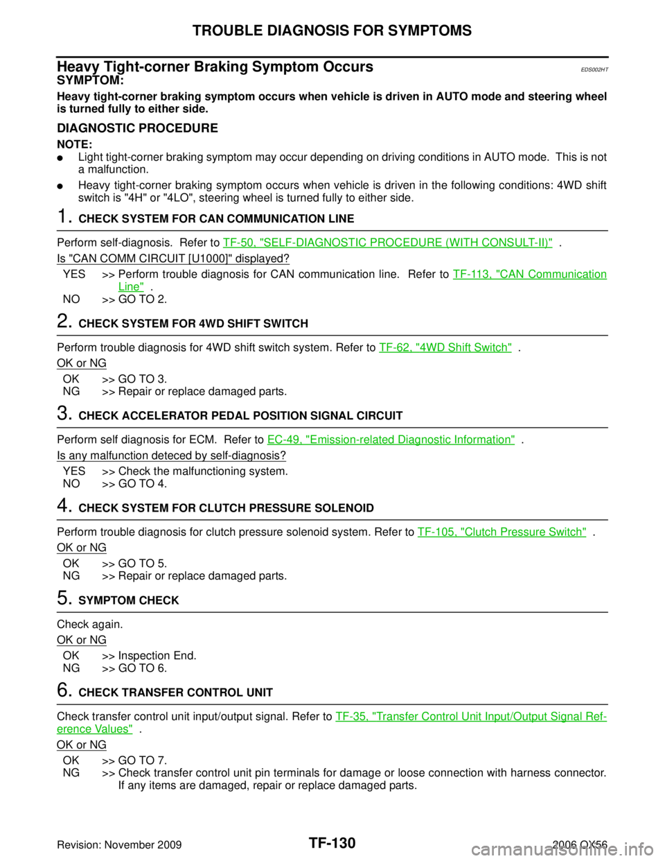
Heavy Tight-corner Braking Symptom OccursEDS002HT
SYMPTOM:
Heavy tight-corner braking symptom occurs when vehicle is driven in AUTO mode and steering wheel
is turned fully to either side.
DIAGNOSTIC PROCEDURE
NOTE:
�Light tight-corner braking symptom may occur depending on driving conditions in AUTO mode. This is not
a malfunction.
�Heavy tight-corner braking symptom occurs when vehicle is driven in the following conditions: 4WD shift
switch is "4H" or "4LO", steering wheel is turned fully to either side.
1. CHECK SYSTEM FOR CAN COMMUNICATION LINE
Perform self-diagnosis. Refer to TF-50, "
SELF-DIAGNOSTIC PROCEDURE (WITH CONSULT-II)" .
Is "CAN COMM CIRCUIT [U1000]" displayed?
YES >> Perform trouble diagnosis for CAN communication line. Refer to TF-113, "CAN Communication
Line" .
NO >> GO TO 2.
2. CHECK SYSTEM FOR 4WD SHIFT SWITCH
Perform trouble diagnosis for 4WD shift switch system. Refer to TF-62, "
4WD Shift Switch" .
OK or NG
OK >> GO TO 3.
NG >> Repair or replace damaged parts.
3. CHECK ACCELERATOR PEDAL POSITION SIGNAL CIRCUIT
Perform self diagnosis for ECM. Refer to EC-49, "
Emission-related Diagnostic Information" .
Is any malfunction deteced by self-diagnosis?
YES >> Check the malfunctioning system.
NO >> GO TO 4.
4. CHECK SYSTEM FOR CLUTCH PRESSURE SOLENOID
Perform trouble diagnosis for clutch pressure solenoid system. Refer to TF-105, "
Clutch Pressure Switch" .
OK or NG
OK >> GO TO 5.
NG >> Repair or replace damaged parts.
5. SYMPTOM CHECK
Check again.
OK or NG
OK >> Inspection End.
NG >> GO TO 6.
6. CHECK TRANSFER CONTROL UNIT
Check transfer control unit input/output signal. Refer to TF-35, "
Transfer Control Unit Input/Output Signal Ref-
erence Values" .
OK or NG
OK >> GO TO 7.
NG >> Check transfer control unit pin terminals for damage or loose connection with harness connector. If any items are damaged, repair or replace damaged parts.
Page 3293 of 3383

WT-4
NOISE, VIBRATION, AND HARSHNESS (NVH) TROUBLESHOOTING
Revision: November 20092006 QX56
NOISE, VIBRATION, AND HARSHNESS (NVH) TROUBLESHOOTINGPFP:00003
NVH Troubleshooting ChartEES001HY
Use the chart below to help you find the cause of the symptom. If necessary, repair or replace these parts.
×: ApplicableReference page
WT-5WT-6WT-38WT-7—
—
WT-38
FFD-6, "
NVH Troubleshooting Chart
" (FFD),
RFD-7, "
NVH Troubleshooting Chart
" (RFD)
FAX-4, "
NVH Troubleshooting Chart
" (FAX),
FSU-4, "
NVH Troubleshooting Chart
" (FSU)
RAX-4, "
NVH Troubleshooting Chart
" (RAX),
RSU-5, "
NVH Troubleshooting Chart
" (RSU)
Refer to TIRES in this chart.
Refer to ROAD WHEEL in this chart.
BR-5, "
NVH Troubleshooting Chart
"
PS-5, "
NVH Troubleshooting Chart
"
Possible cause and SUSPECTED PARTS
Out-of-round
Imbalance
Incorrect tire pressure
Uneven tire wear
Deformation or damage
Non-uniformity
Incorrect tire size
DIFFERENTIAL
FRONT AXLE AND FRONT SUSPENSION
REAR AXLE AND REAR SUSPENSION
TIRES
ROAD WHEEL
BRAKE
STEERING
Symptom TIRESNoise
× ××××× × × ×× ××
Shake × ×××× × × ×× ××
Vibration ××××××
Shimmy × ×××××× × ×× ××
Shudder × ×××× × × ×× ××
Poor quality ride or
handling × ×××× × × ××
ROAD
WHEEL Noise
×××× ×××××
Shake ×× × ×× ×××
Shimmy, shudder ×× × ×× ×××
Poor quality ride or
handling ×× ×
×× ×
Page 3326 of 3383
REMOVAL AND INSTALLATIONWT-37
C
DF
G H
I
J
K L
M A
B
WT
Revision: November 2009 2006 QX56
3. Place wheel on turntable of tire machine. Ensure that transmitter
is 270 degrees from mounting/dismounting head.
NOTE:
Do not touch transmitter with mounting head.
4. Lubricate tire well, and install second side of tire as normal. Ensure that tire does not rotate relative to rim.
5. Inflate tire and balance the wheel and tire assembly. Refer to WT-6, "
Wheel Balance Adjustment" .
6. Install Wheel and tire assembly in appropriate wheel position on vehicle.
NOTE:
If replacing the transmitter, then transmitter wake up operation must be performed. Refer to WT-18,
"Transmitter Wake Up Operation" .
7. Adjust neutral position of steering angle sensor. Refer to BRC-62, "
Adjustment of Steering Angle Sensor
Neutral Position" .
WEIA0046E
Page 3357 of 3383
WW-30
FRONT WIPER AND WASHER SYSTEM
Revision: November 20092006 QX56
Washer Tube Layout EKS00BE7
Wiper and Washer Switch EKS00BE8
REMOVAL AND INSTALLATION
Removal
1. Remove steering column covers.
2. Remove wiper washer switch connector.
3. Pinch tabs at wiper and washer switch base and slide switch
away from steering column to remove.
INSTALLATION
Installation is in the reverse order of removal.
Washer Fluid Reservoir EKS00GBI
REMOVAL AND INSTALLATION
Removal
1. Remove side washer fluid reservoir screw.
2. Remove front and rear washer motor connector.
WKIA4465E
1. Rear washer nozzle 2. Washer nozzles 3. Washer fluid reservoir
WKIA0071E
LKIA0411E