Page 1760 of 3383
DTC P2122, P2123 APP SENSOREC-549
C
DE
F
G H
I
J
K L
M A
EC
Revision: November 2009 2006 QX56
Wiring DiagramUBS00HC8
BBWA1706E
Page 1762 of 3383
DTC P2122, P2123 APP SENSOREC-551
C
DE
F
G H
I
J
K L
M A
EC
Revision: November 2009 2006 QX56
2. CHECK APP SENSOR 1 POWER SUPPLY CIRCUIT
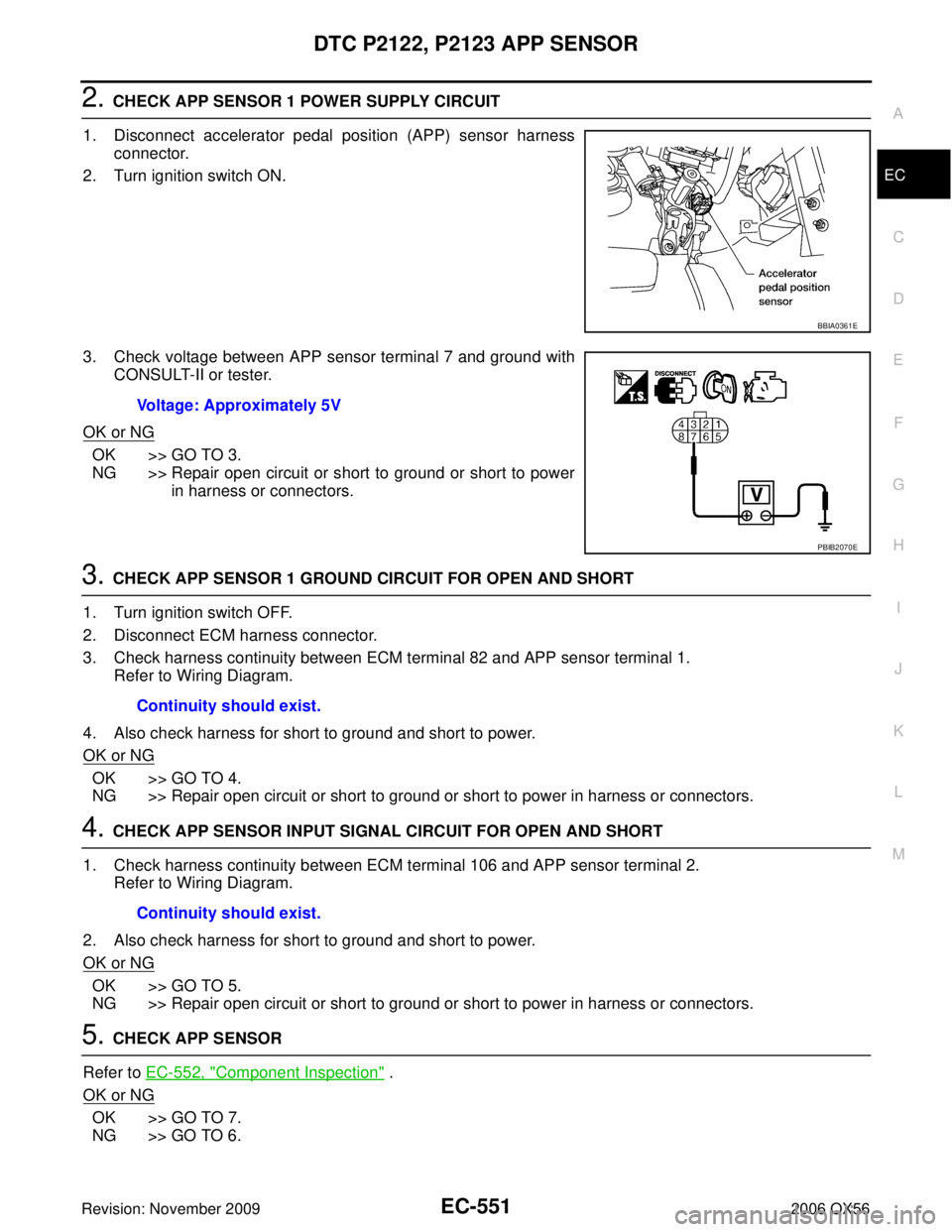
1. Disconnect accelerator pedal position (APP) sensor harness connector.
2. Turn ignition switch ON.
3. Check voltage between APP sensor terminal 7 and ground with CONSULT-II or tester.
OK or NG
OK >> GO TO 3.
NG >> Repair open circuit or short to ground or short to power in harness or connectors.
3. CHECK APP SENSOR 1 GROUND CIRCUIT FOR OPEN AND SHORT
1. Turn ignition switch OFF.
2. Disconnect ECM harness connector.
3. Check harness continuity between ECM terminal 82 and APP sensor terminal 1. Refer to Wiring Diagram.
4. Also check harness for short to ground and short to power.
OK or NG
OK >> GO TO 4.
NG >> Repair open circuit or short to ground or short to power in harness or connectors.
4. CHECK APP SENSOR INPUT SIGNAL CIRCUIT FOR OPEN AND SHORT
1. Check harness continuity between ECM terminal 106 and APP sensor terminal 2. Refer to Wiring Diagram.
2. Also check harness for short to ground and short to power.
OK or NG
OK >> GO TO 5.
NG >> Repair open circuit or short to ground or short to power in harness or connectors.
5. CHECK APP SENSOR
Refer to EC-552, "
Component Inspection" .
OK or NG
OK >> GO TO 7.
NG >> GO TO 6.
BBIA0361E
Voltage: Approximately 5V
PBIB2070E
Continuity should exist.
Continuity should exist.
Page 1766 of 3383
DTC P2127, P2128 APP SENSOREC-555
C
DE
F
G H
I
J
K L
M A
EC
Revision: November 2009 2006 QX56
Wiring DiagramUBS00HCG
BBWA1707E
Page 1768 of 3383
DTC P2127, P2128 APP SENSOREC-557
C
DE
F
G H
I
J
K L
M A
EC
Revision: November 2009 2006 QX56
2. CHECK APP SENSOR 2 POWER SUPPLY CIRCUIT-I
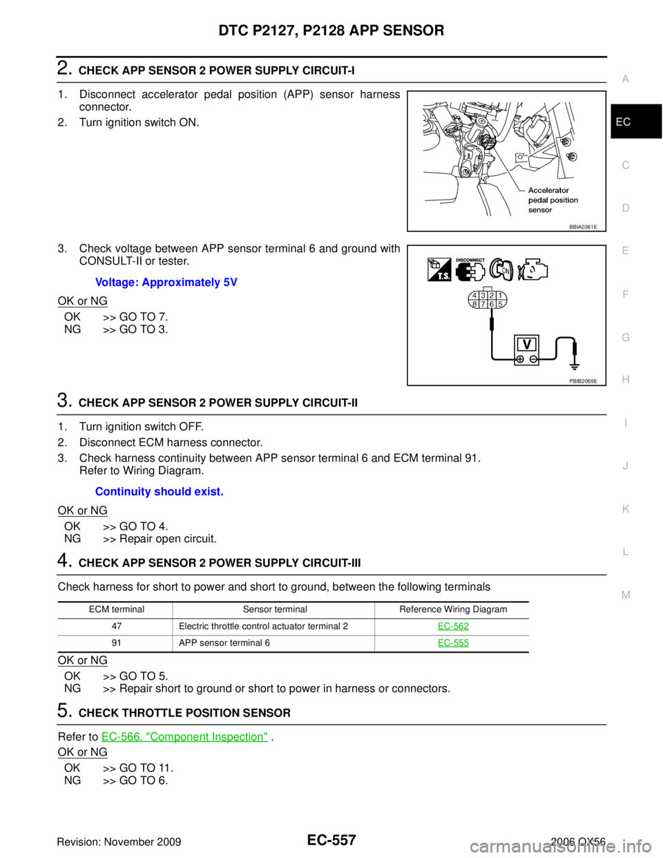
1. Disconnect accelerator pedal position (APP) sensor harness connector.
2. Turn ignition switch ON.
3. Check voltage between APP sensor terminal 6 and ground with CONSULT-II or tester.
OK or NG
OK >> GO TO 7.
NG >> GO TO 3.
3. CHECK APP SENSOR 2 POWER SUPPLY CIRCUIT-II
1. Turn ignition switch OFF.
2. Disconnect ECM harness connector.
3. Check harness continuity between APP sensor terminal 6 and ECM terminal 91. Refer to Wiring Diagram.
OK or NG
OK >> GO TO 4.
NG >> Repair open circuit.
4. CHECK APP SENSOR 2 POWER SUPPLY CIRCUIT-III
Check harness for short to power and short to ground, between the following terminals
OK or NG
OK >> GO TO 5.
NG >> Repair short to ground or short to power in harness or connectors.
5. CHECK THROTTLE POSITION SENSOR
Refer to EC-566, "
Component Inspection" .
OK or NG
OK >> GO TO 11.
NG >> GO TO 6.
BBIA0361E
Voltage: Approximately 5V
PBIB2069E
Continuity should exist.
ECM terminal Sensor terminal Reference Wiring Diagram
47 Electric throttle control actuator terminal 2 EC-562
91APP sensor terminal 6 EC-555
Page 1769 of 3383
EC-558Revision: November 2009
DTC P2127, P2128 APP SENSOR
2006 QX56
6. REPLACE ELECTRIC THROTTLE CONTROL ACTUATOR
1. Replace the electric throttle control actuator.
2. Perform EC-78, "
Throttle Valve Closed Position Learning" .
3. Perform EC-78, "
Idle Air Volume Learning" .
>> INSPECTION END
7. CHECK APP SENSOR 2 GROUND CIRCUIT FOR OPEN AND SHORT
1. Turn ignition switch OFF.
2. Disconnect ECM harness connector.
3. Check harness continuity between ECM terminal 83 and APP sensor terminal 3. Refer to Wiring Diagram.
4. Also check harness for short to ground and short to power.
OK or NG
OK >> GO TO 8.
NG >> Repair open circuit or short to ground or short to power in harness or connectors.
8. CHECK APP SENSOR 2 INPUT SIGNAL CIRCUIT FOR OPEN AND SHORT
1. Check harness continuity between ECM terminal 98 and APP sensor terminal 5. Refer to Wiring Diagram.
2. Also check harness for short to ground and short to power.
OK or NG
OK >> GO TO 9.
NG >> Repair open circuit or short to ground or short to power in harness or connectors.
9. CHECK APP SENSOR
Refer to EC-559, "
Component Inspection" .
OK or NG
OK >> GO TO 11.
NG >> GO TO 10.
10. REPLACE ACCELERATOR PEDAL ASSEMBLY
1. Replace the accelerator pedal assembly.
2. Perform EC-78, "
Accelerator Pedal Released Position Learning" .
3. Perform EC-78, "
Throttle Valve Closed Position Learning" .
4. Perform EC-78, "
Idle Air Volume Learning" .
>> INSPECTION END
11 . CHECK INTERMITTENT INCIDENT
Refer to EC-144, "
TROUBLE DIAGNOSIS FOR INTERMITTENT INCIDENT" .
>> INSPECTION END
Continuity should exist.
Continuity should exist.
Page 1773 of 3383
EC-562Revision: November 2009
DTC P2135 TP SENSOR
2006 QX56
Wiring DiagramUBS00HCO
BBWA2093E
Page 1775 of 3383
EC-564Revision: November 2009
DTC P2135 TP SENSOR
2006 QX56
2. CHECK THROTTLE POSITION SENSOR POWER SUPPLY CIRCUIT-I
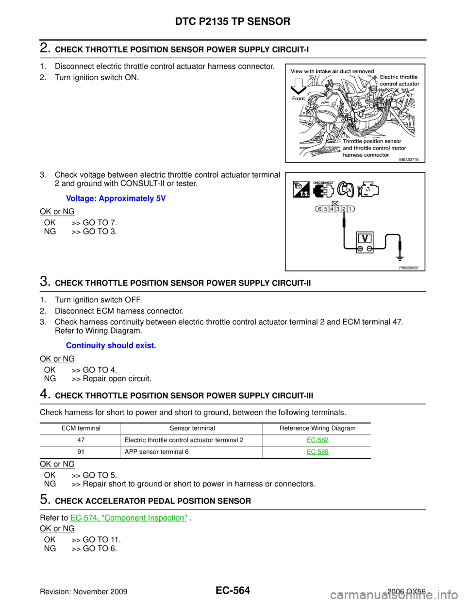
1. Disconnect electric throttle control actuator harness connector.
2. Turn ignition switch ON.
3. Check voltage between electric throttle control actuator terminal 2 and ground with CONSULT-II or tester.
OK or NG
OK >> GO TO 7.
NG >> GO TO 3.
3. CHECK THROTTLE POSITION SENSOR POWER SUPPLY CIRCUIT-II
1. Turn ignition switch OFF.
2. Disconnect ECM harness connector.
3. Check harness continuity between electric throttle control actuator terminal 2 and ECM terminal 47. Refer to Wiring Diagram.
OK or NG
OK >> GO TO 4.
NG >> Repair open circuit.
4. CHECK THROTTLE POSITION SENSOR POWER SUPPLY CIRCUIT-III
Check harness for short to power and short to ground, between the following terminals.
OK or NG
OK >> GO TO 5.
NG >> Repair short to ground or short to power in harness or connectors.
5. CHECK ACCELERATOR PEDAL POSITION SENSOR
Refer to EC-574, "
Component Inspection" .
OK or NG
OK >> GO TO 11.
NG >> GO TO 6.
BBIA0371E
Voltage: Approximately 5V
PBIB2065E
Continuity should exist.
ECM terminal Sensor terminal Reference Wiring Diagram
47 Electric throttle control actuator terminal 2 EC-562
91APP sensor terminal 6 EC-569
Page 1776 of 3383
DTC P2135 TP SENSOREC-565
C
DE
F
G H
I
J
K L
M A
EC
Revision: November 2009 2006 QX56
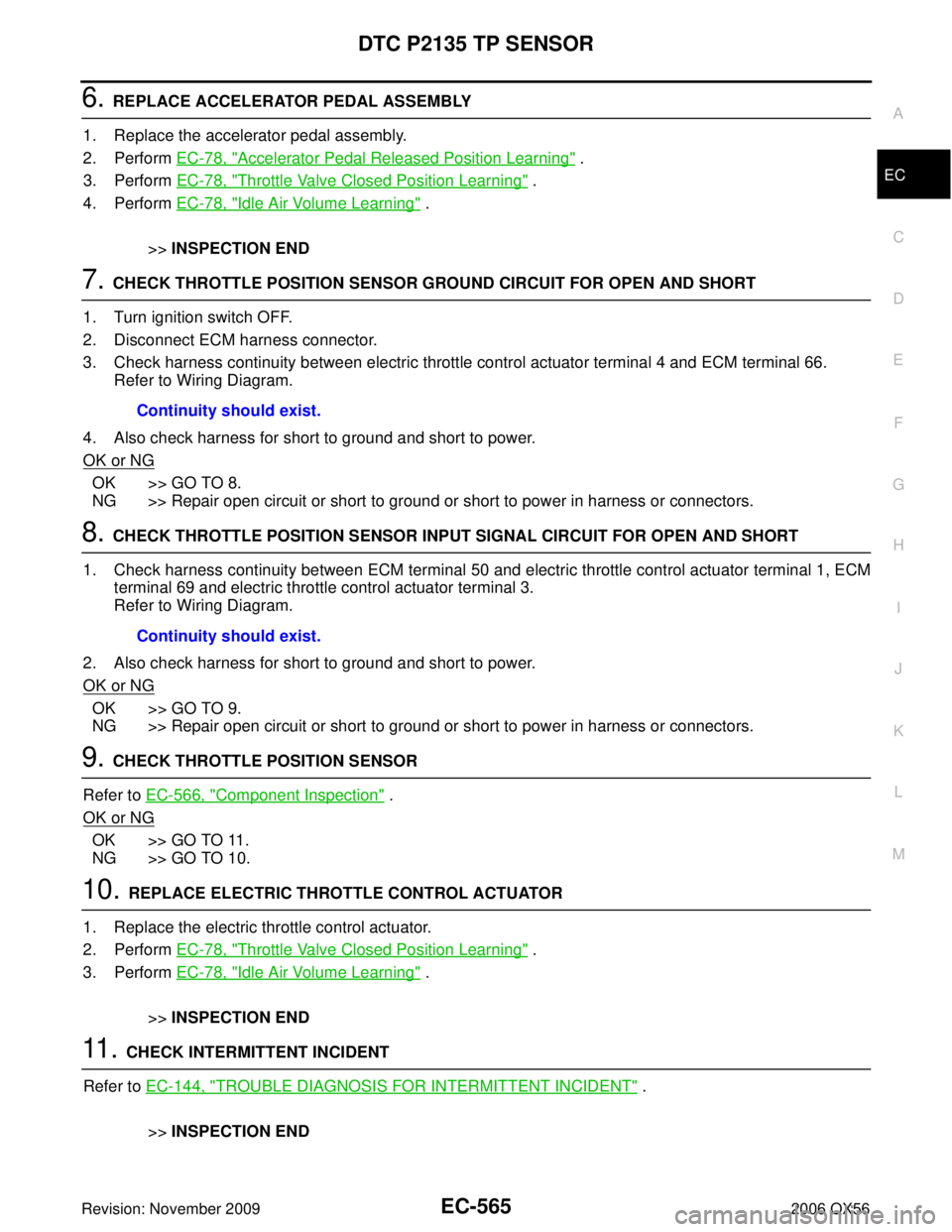
6. REPLACE ACCELERATOR PEDAL ASSEMBLY
1. Replace the accelerator pedal assembly.
2. Perform EC-78, "
Accelerator Pedal Released Position Learning" .
3. Perform EC-78, "
Throttle Valve Closed Position Learning" .
4. Perform EC-78, "
Idle Air Volume Learning" .
>> INSPECTION END
7. CHECK THROTTLE POSITION SENSOR GROUND CIRCUIT FOR OPEN AND SHORT
1. Turn ignition switch OFF.
2. Disconnect ECM harness connector.
3. Check harness continuity between electric throttle control actuator terminal 4 and ECM terminal 66. Refer to Wiring Diagram.
4. Also check harness for short to ground and short to power.
OK or NG
OK >> GO TO 8.
NG >> Repair open circuit or short to ground or short to power in harness or connectors.
8. CHECK THROTTLE POSITION SENSOR INPUT SIGNAL CIRCUIT FOR OPEN AND SHORT
1. Check harness continuity between ECM terminal 50 and electric throttle control actuator terminal 1, ECM terminal 69 and electric throttle control actuator terminal 3.
Refer to Wiring Diagram.
2. Also check harness for short to ground and short to power.
OK or NG
OK >> GO TO 9.
NG >> Repair open circuit or short to ground or short to power in harness or connectors.
9. CHECK THROTTLE POSITION SENSOR
Refer to EC-566, "
Component Inspection" .
OK or NG
OK >> GO TO 11.
NG >> GO TO 10.
10. REPLACE ELECTRIC THROTTLE CONTROL ACTUATOR
1. Replace the electric throttle control actuator.
2. Perform EC-78, "
Throttle Valve Closed Position Learning" .
3. Perform EC-78, "
Idle Air Volume Learning" .
>> INSPECTION END
11 . CHECK INTERMITTENT INCIDENT
Refer to EC-144, "
TROUBLE DIAGNOSIS FOR INTERMITTENT INCIDENT" .
>> INSPECTION END
Continuity should exist.
Continuity should exist.