Page 3250 of 3383

TRANSFER ASSEMBLYTF-145
CE F
G H
I
J
K L
M A
B
TF
Revision: November 2009 2006 QX56
TRANSFER ASSEMBLYPFP:33100
Removal and InstallationEDS003BF
REMOVAL
1. Remove the drain plug and gasket. Drain the fluid. Refer to TF-11, "DRAINING" .
2. Remove the A/T undercover using power tool.
3. Remove the center exhaust tube and main muffler. Refer to EX-3, "
Removal and Installation" .
4. Remove the front and rear propeller shafts. Refer to PR-4, "
Removal and Installation" (front), PR-8,
"Removal and Installation" (rear).
CAUTION:
Do not damage spline, sleeve yoke and rear oil seal when removing rear propeller shaft.
NOTE:
Insert a plug into the rear oil seal after removing the rear propeller shaft.
5. Remove the A/T nuts from the A/T crossmember.
6. Position two suitable jacks under the A/T and transfer assembly.
7. Remove the crossmember. Refer to AT- 2 4 6 , "
COMPONENTS" .
WARNING:
Support A/T and transfer assembly using two suitable jacks while removing crossmember.
8. Disconnect the electrical connectors from the following:
�AT P s w i t c h
�Neutral 4LO switch
�Wait detection switch
�Transfer motor
�Transfer control device
�Transfer terminal cord assembly
9. Disconnect each air breather hose from the following. Refer to TF-139, "
Removal and Installation" .
�Actuator
�Breather tube (transfer)
�Transfer motor (case connector)
10. Remove the transfer control device from the extension housing.
11. Remove the transfer to A/T and A/T to transfer bolts. WARNING:
Support transfer assembly with suitable jack while removing it.
12. Remove the transfer assembly.
INSTALLATION
Installation is in the reverse order of removal.
�Tighten the bolts to specification.
�After installation check the transfer fluid level and for fluid leak-
age. Refer to TF-11, "
TRANSFER FLUID" .
�After filling, start the engine and let it run for one minute. Then
stop the engine and recheck the transfer fluid.Bolt length : 45 mm (1.77 in)
Transfer bolt torque : 36 N·m (3.7 kg-m, 27 ft-lb)
SDIA3181E
Page 3272 of 3383
TRANSFER ASSEMBLYTF-167
CE F
G H
I
J
K L
M A
B
TF
Revision: November 2009 2006 QX56
ASSEMBLY
Center Case
1. Apply ATF to the new O-ring, and install it on the oil filter stud.
CAUTION:
Do not reuse O-ring.
2. Install the oil filter stud to the oil filter.
3. Apply ATF to the two new O-rings (1), and install them on the oil filter (2).
CAUTION:
Do not reuse O-rings.
4. Install the oil filter to the center case. Tighten the bolts to the specified torque. Refer to TF-146, "
COMPONENTS" .
CAUTION:
�Do not damage oil filter.
�Attach oil filter and tighten bolts evenly.
5. Install the outer gear and inner gear into the sub oil pump hous- ing, and measure the side clearance. Refer to TF-165, "
Sub-oil
Pump" .
SDIA3180E
WDIA0285E
SDIA2136E
SDIA2135E
Page 3273 of 3383

TF-168
TRANSFER ASSEMBLY
Revision: November 20092006 QX56
6. Align the dowel pin hole and bolt hole of the sub oil pump
assembly with the center case. Install the sub oil pump cover.
Then tighten to the specified torque. Refer to TF-146, "
COMPO-
NENTS" .
7. Apply ATF to the new O-ring and install it to the transfer motor. CAUTION:
Do not reuse O-ring.
8. Fit the double-flat end of the transfer motor shaft into the slot of the sub-oil pump assembly. Then tighten to the specified torque.
Refer to TF-146, "
COMPONENTS" .
CAUTION:
Be sure to install connector bracket.
9. Assemble the control valve assembly with the following procedure. CAUTION:
�Do not reuse any part that has been dropped or damaged.
�Make sure valve is assembled in the proper direction.
�Do not use a magnet because residual magnetism stays during assembly.
a. Clean the upper body, control valves and springs with cleaning agent, and dry with compressed air.
b. Dip the control valves in ATF, and apply ATF to the valve-mount- ing area of the upper body.
c. Install each control valve, spring, and plug to the upper body, and install retainer plates to hold them in place.
CAUTION:
�To insert control valves into upper body, place upper
body on a level surface in order to prevent flaw or dam-
age.
�Make sure each control valve is smoothly inserted.
SDIA2328E
SDIA2787E
SDIA3317E
SDIA2127E
Page 3275 of 3383
TF-170
TRANSFER ASSEMBLY
Revision: November 20092006 QX56
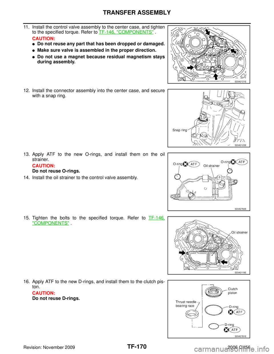
11. Install the control valve assembly to the center case, and tighten
to the specified torque. Refer to TF-146, "
COMPONENTS" .
CAUTION:
�Do not reuse any part that has been dropped or damaged.
�Make sure valve is assembled in the proper direction.
�Do not use a magnet because residual magnetism stays
during assembly.
12. Install the connector assembly into the center case, and secure with a snap ring.
13. Apply ATF to the new O-rings, and install them on the oil strainer.
CAUTION:
Do not reuse O-rings.
14. Install the oil strainer to the control valve assembly.
15. Tighten the bolts to the specified torque. Refer to TF-146,
"COMPONENTS" .
16. Apply ATF to the new D-rings, and install them to the clutch pis- ton.
CAUTION:
Do not reuse D-rings.
SDIA2121E
SDIA2122E
SDIA2782E
SDIA2119E
SDIA2781E
Page 3276 of 3383

TRANSFER ASSEMBLYTF-171
CE F
G H
I
J
K L
M A
B
TF
Revision: November 2009 2006 QX56
17. Install the thrust needle bearing race to the clutch piston.
18. Install the clutch piston to the center case as shown.
CAUTION:
Install so the fitting protrusion of clutch piston aligns with
the dent of center case.
19. Remove all the sealant from the oil pressure check port and inside the center case.
CAUTION:
Remove old sealant adhering to mating surfaces. Also
remove any moisture, oil, or foreign material adhering to
application and mating surfaces.
20. Thread the new oil pressure check plug in 1 or 2 pitches and apply sealant to the oil pressure check plug threads. Tighten to
the specified torque. Refer to TF-146, "
COMPONENTS" .
�Use Genuine Silicone RTV or equivalent. Refer to GI-46,
"RECOMMENDED CHEMICAL PRODUCTS AND SEAL-
ANTS" .
CAUTION:
Do not reuse oil pressure check plug.
21. Install the new snap ring to the clutch hub using suitable tool. CAUTION:
Do not reuse snap ring.
SDIA2189E
SDIA2190E
SDIA3188E
WDIA0101E
Page 3280 of 3383

TRANSFER ASSEMBLYTF-175
CE F
G H
I
J
K L
M A
B
TF
Revision: November 2009 2006 QX56
37. Install the inner gear and outer gear in the main oil pump hous-
ing. Then measure the side clearance. Refer to TF-165, "
Main
Oil Pump" .
38. Install the main oil pump housing, outer gear and inner gear to the center case.
39. Install the main oil pump cover to the center case, and tighten to the specified torque. Refer to TF-146, "
COMPONENTS" .
40. Remove all the sealant from the switch mating area and inside the center case.
CAUTION:
Remove old sealant adhering to mating surfaces. Also
remove any moisture, oil, or foreign material adhering to
application and mating surfaces.
41. Thread the ATP switch and neutral-4LO switch in one to two pitches and apply sealant to the threads of the switches. Tighten
to the specified torque. Refer to TF-146, "
COMPONENTS" .
�Use Genuine Silicone RTV or equivalent. Refer to GI-46,
"RECOMMENDED CHEMICAL PRODUCTS AND SEAL-
ANTS" .
NOTE:
�Neutral-4LO switch harness connector is gray.
�ATP switch harness connector is black.
SDIA2174E
SDIA2188E
SDIA2130E
SDIA3435E
Page 3285 of 3383

TF-180
TRANSFER ASSEMBLY
Revision: November 20092006 QX56
18. Apply liquid gasket to the entire center case mating surface of
the front case assembly as shown.
�Use Genuine Anaerobic Liquid Gasket or equivalent.
Refer to GI-46, "
RECOMMENDED CHEMICAL PRODUCTS
AND SEALANTS" .
CAUTION:
Remove all foreign materials such as water, oil and grease
from center case and front case mating surfaces.
19. Install the center case assembly to the front case assembly. CAUTION:
Do not damage mainshaft end.
20. Tap the center case lightly and press-fit the front drive shaft bearing into the front case.
21. Tighten the front case bolts to the specified torque. Refer to TF-
146, "COMPONENTS" .
CAUTION:
Be sure to install harness bracket and air breather hose
clamp.
22. Install the drain plug with a new gasket. CAUTION:
Do not reuse gasket.
23. Align the matching mark on the front drive shaft with the mark on the companion flange, then install the companion flange.
WDIA0157E
SDIA2138E
SDIA2100E
SDIA2779E
Page 3286 of 3383

TRANSFER ASSEMBLYTF-181
CE F
G H
I
J
K L
M A
B
TF
Revision: November 2009 2006 QX56
24. Install the new companion flange self-lock nut. Tighten to the
specified torque using Tool. Refer to TF-146, "
COMPONENTS" .
CAUTION:
Do not reuse self-lock nut.
25. Remove all the sealant from the check plug, switch mating sur- face and front case.
CAUTION:
Remove old sealant adhering to mating surfaces. Also
remove any moisture, oil, or foreign material adhering to
application and mating surfaces.
26. Install the check ball and check spring to the front case. Apply silicone gasket, to the check plug and wait detection switch and
install them to the front case. Tighten to the specified torque.
Refer to TF-146, "
COMPONENTS" .
�Use Genuine Silicone RTV or equivalent. Refer to GI-46,
"RECOMMENDED CHEMICAL PRODUCTS AND SEAL-
ANTS" .
NOTE:
Wait detection switch harness connector is black.
27. Install the new oil seal in the front case using Tool.
CAUTION:
�Do not reuse oil seal.
�Apply petroleum jelly to seal lip before installing.
28. Install the shift lever to the shift cross.
29. Install the lock pin and lock pin nut. Tighten to the specified torque. Refer to TF-146, "
COMPONENTS" .
Rear Case
1. Apply petroleum jelly to the circumference of the new rear oil
seal. Install the new rear oil seal so that it is flush with the case
tip face using Tool.
CAUTION:
�Do not reuse oil seal.
�Apply petroleum jelly to seal lip before installing.Tool number : KV40104000 ( — )
WDIA0219E
Tool number : ST22360002 (J-25679-01)
WDIA0158E
SDIA2182E
Tool number : ST30720000 (J-25405)
SDIA2204E