Page 2666 of 3383
PG-25
C
DE
F
G H
I
J
L
M A
B
PG
Revision: November 2009 2006 QX56
Concept of Auto Active Test
�IPDM E/R actuates auto active test mode when")
IPDM E/R (INTELLIGENT POWER DISTRIBUTION MODULE ENGINE ROOM)PG-25
C
DE
F
G H
I
J
L
M A
B
PG
Revision: November 2009 2006 QX56
Concept of Auto Active Test
�IPDM E/R actuates auto active test mode when it receives door switch signal from BCM via CAN commu-
nication line. Therefore, when auto active test mode is activated successfully, CAN communication
between IPDM E/R and BCM is normal.
�If any of the systems controlled by IPDM E/R cannot be operated, possible cause can be easily diagnosed
using auto active test.
Diagnosis chart in auto active test mode
Item Number Test Item Operation Time/Frequency
1 Rear window defogger 10 seconds
2 Front wipers LOW 5 seconds then HIGH 5 seconds
3 Tail, license, and parking lamps 10 seconds
4 Front fog lamps 10 seconds
5 Headlamps Low on for 10 seconds. High on-off five times.
6 A/C compressor (magnetic clutch) ON-OFF 5 times
7 Cooling fan 10 seconds
SymptomInspection contents Possible cause
Rear window defogger
does not operate. Perform auto active
test. Does rear win-
dow defogger oper-
ate?YES
�BCM signal input circuit
NO
�Rear window defogger relay
�Open circuit of rear window defogger
�IPDM E/R malfunction
�Harness or connector malfunction between IPDM E/R and rear window
defogger
Any of front wipers, tail
and parking lamps, front
fog lamps, and head-
lamps (Hi, Lo) do not
operate. Perform auto active
test. Does system in
question operate?YES
�BCM signal input system
NO
�Lamp/wiper motor malfunction
�Lamp/wiper motor ground circuit malfunction
�Harness/connector malfunction between IPDM E/R and system in
question
�IPDM E/R (integrated relay) malfunction
A/C compressor does
not operate. Perform auto active
test. Does magnet
clutch operate?YES
�BCM signal input circuit
�CAN communication signal between BCM and ECM
�CAN communication signal between ECM and IPDM E/R
NO
�Magnet clutch malfunction
�Harness/connector malfunction between IPDM E/R and magnet clutch
�IPDM E/R (integrated relay) malfunction
Cooling fan does not
operate. Perform auto active
test. Does cooling fan
operate?YES
�ECM signal input circuit
�CAN communication signal between ECM and IPDM E/R
NO
�Cooling fan motor malfunction
�Harness/connector malfunction between IPDM E/R and cooling fan
motor
�IPDM E/R (integrated relay) malfunction
Page 2682 of 3383

HARNESSPG-41
C
DE
F
G H
I
J
L
M A
B
PG
Revision: November 2009 2006 QX56
HARNESSPFP:24010
Harness LayoutEKS00BND
HOW TO READ HARNESS LAYOUT
The following Harness Layouts use a map style grid to help locate
connectors on the drawings:
�Main Harness
�Engine Room Harness LH View (Engine Compartment)
�Engine Room Harness RH View (Engine Compartment)
�Engine Control Harness
�Chassis Harness and Rear Sonar Sensor Sub-harness
�Body Harness
�Body No. 2 Harness
To use the grid reference
1. Find the desired connector number on the connector list.
2. Find the grid reference.
3. On the drawing, find the crossing of the grid reference letter column and number row.
4. Find the connector number in the crossing zone.
5. Follow the line (if used) to the connector.
CONNECTOR SYMBOL
Main symbols of connector (in Harness Layout) are indicated below.
SEL252V
Connector type Water proof type Standard type
Male Female Male Female
�Cavity: 4 or Less
�Relay connector
�Cavity: From 5 to 8
�Cavity: 9 or More
�Ground terminal etc. —
Page 2703 of 3383
EKS00BNE
Use the chart below to find out what each wiring diagram code stands for.
Refer to the wiring diagram code in t")
PG-62
HARNESS
Revision: November 20092006 QX56
Wiring Diagram Codes (Cell Codes)EKS00BNE
Use the chart below to find out what each wiring diagram code stands for.
Refer to the wiring diagram code in the alphabetical index to find the location (page number) of each wiring
diagram.
CodeSection Wiring Diagram Name
A/C,A ATC Auto Air Conditioner
A/SUSP RSU Rear Air Suspension
AF1B1 EC Air Fuel Ratio (A/F) Sensor 1 (Bank 1)
AF1B2 EC Air Fuel Ratio (A/F) Sensor 1 (Bank 2)
AF1HB1 EC Air Fuel Ratio (A/F) Sensor 1 (Bank 1)
AF1HB2 EC Air Fuel Ratio (A/F) Sensor 1 (Bank 2)
APPS1 EC Accelerator Pedal Position Sensor
APPS2 EC Accelerator Pedal Position Sensor
APPS3 EC Accelerator Pedal Position Sensor
ASC/BS EC ASCD Brake Switch
ASC/SW EC ASCD Steering Switch
ASCBOF EC ASCD Brake Switch
ASCIND EC ASCD Indicator
A/T AT A/T Assembly
AT/IND DI A/T Indicator Lamp
AUDIO AV Audio
AUT/DP SE Automatic Drive Positioner
AUTO/L LT Auto Light Control
B/CLOS BL Back Door Auto Closure System
BACK/L LT Back-up Lamp
BRK/SW EC Brake Switch
CAN EC CAN Communication Line
CAN LAN CAN System
CHARGE SC Charging System
CHIME DI Warning Chime
CLOCK DI Clock
COOL/F EC Cooling Fan Control
COMBSW LT Combination Switch
COMM AV Audio Visual Communication System
COMPAS DI Compass and Thermometer
D/LOCK BL Power Door Lock
DEF GW Rear Window Defogger
DTRL LT Headlamp - With Daytime Light System
DVD AV DVD Entertainment System
ECM/PW EC ECM Power Supply for Back-Up
ECTS EC Engine Coolant Temperature Sensor
ETC1 EC Electric Throttle Control Function
ETC2 EC Throttle Control Motor Relay
ETC3 EC Throttle Control Motor
F/FOG LT Front Fog Lamp
F/PUMP EC Fuel Pump
FTTS EC Fuel Tank Temperature Sensor
FUELB1 EC Fuel Injection System Bank 1
FUELB2 EC Fuel Injection System Bank 2
H/AIM LT Headlamp Aiming Control
H/PHON AV Hands Free Telephone
H/LAMP LT Headlamp
Page 2713 of 3383
PG-72
STANDARDIZED RELAY
Revision: November 20092006 QX56
STANDARDIZED RELAYPFP:25230
DescriptionEKS00BNL
NORMAL OPEN, NORMAL CLOSED AND MIXED TYPE RELAYS
Relays can mainly be divided into three types: normal open, normal closed and mixed type relays.
TYPE OF STANDARDIZED RELAYS
SEL881H
SEL882H
1M1 Make 2M2 Make
1T 1 Transfer 1M·1B 1 Make 1 Break
Page 2714 of 3383
STANDARDIZED RELAYPG-73
C
DE
F
G H
I
J
L
M A
B
PG
Revision: November 2009 2006 QX56
WKIA0253E
Page 2719 of 3383
PG-78
FUSE AND RELAY BOX
Revision: November 20092006 QX56
FUSE AND RELAY BOXPFP:24012
Terminal ArrangementEKS00BNP
WKIA4692E
Page 2785 of 3383
RF-10
SUNROOF
Revision: November 20092006 QX56
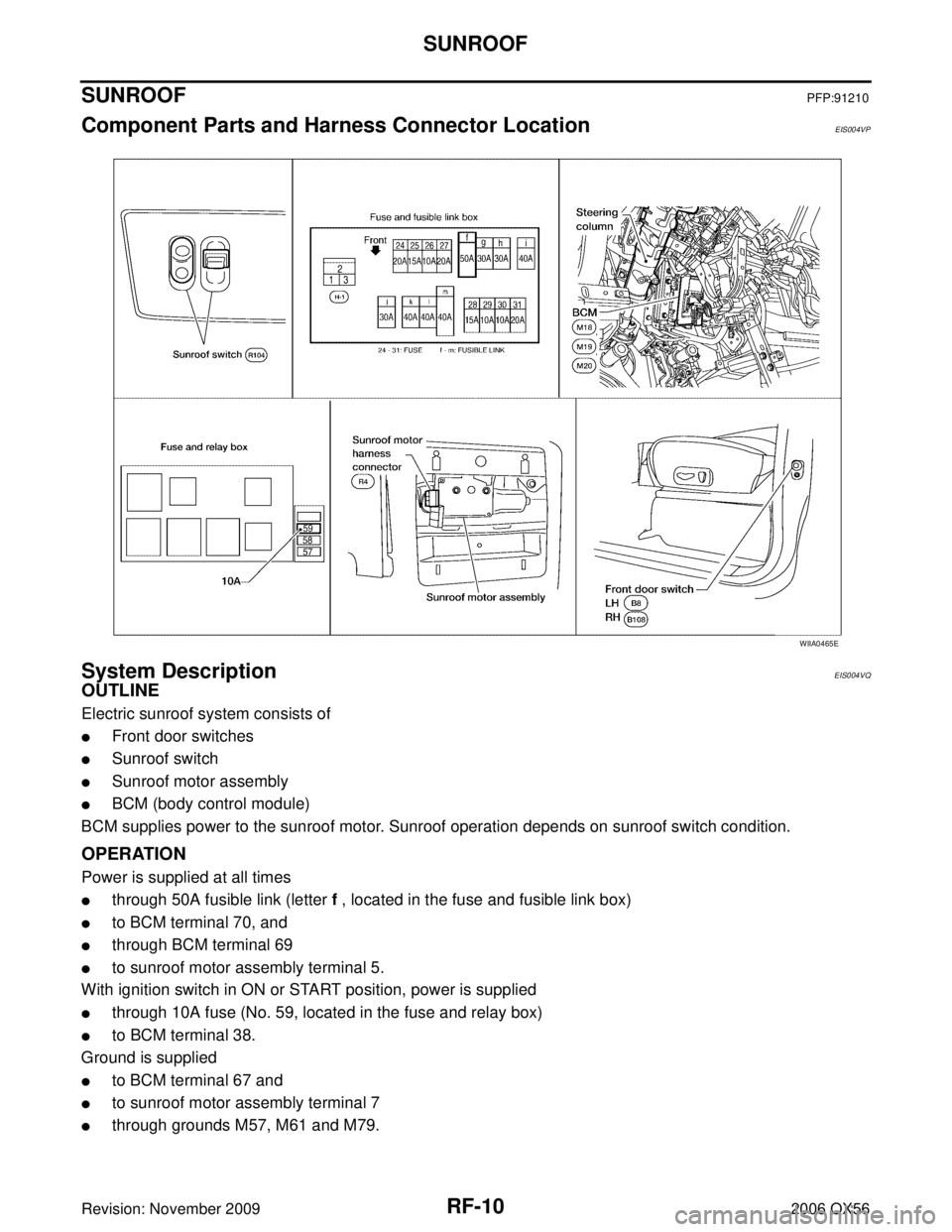
SUNROOFPFP:91210
Component Parts and Harness Connector LocationEIS004VP
System DescriptionEIS004VQ
OUTLINE
Electric sunroof system consists of
�Front door switches
�Sunroof switch
�Sunroof motor assembly
�BCM (body control module)
BCM supplies power to the sunroof motor. Sunroof operation depends on sunroof switch condition.
OPERATION
Power is supplied at all times
�through 50A fusible link (letter f , located in the fuse and fusible link box)
�to BCM terminal 70, and
�through BCM terminal 69
�to sunroof motor assembly terminal 5.
With ignition switch in ON or START position, power is supplied
�through 10A fuse (No. 59, located in the fuse and relay box)
�to BCM terminal 38.
Ground is supplied
�to BCM terminal 67 and
�to sunroof motor assembly terminal 7
�through grounds M57, M61 and M79.
WIIA0465E
Page 2793 of 3383

RF-18
SUNROOF
Revision: November 20092006 QX56
BCM Power Supply and Ground Circuit CheckEIS004W1
1. CHECK FUSE
Check the following BCM fuse and fusible link.
NOTE:
Refer to RF-10, "
Component Parts and Harness Connector Location" .
OK or NG
OK >> GO TO 2.
NG >> If fuse is blown, be sure to eliminate cause of problem before installing new fuse. Refer to PG-4,
"POWER SUPPLY ROUTING CIRCUIT" .
2. CHECK POWER SUPPLY CIRCUIT
1. Turn ignition switch OFF.
2. Disconnect BCM connectors.
3. Check voltage between BCM connectors M18 and M20 termi- nals 38, 70 and ground.
OK or NG
OK >> GO TO 3.
NG >> Repair or replace harness.
3. CHECK GROUND CIRCUIT
Check continuity between BCM connector M20 terminal 67 and
ground.
OK or NG
OK >> Power supply and ground circuit is OK.
NG >> Repair or replace harness.
Retained power operation does not operate properly. 1. Check the retained power operation mode setting
RF-112. BCM power supply and ground circuit checkRF-18
3. Door switch checkRF-21
4. Replace sunroof motor assemblyRF-27
Motor does not stop at the sunroof fully-open or fully-
closed position.1. Initialization procedure check
RF-11
2. Replace sunroof motor assemblyRF-27
Sunroof does not do the interruption detection.1. Replace sunroof motor assembly RF-27
SymptomDiagnostic procedure and repair order Refer to page
Component PartsTerminal No. (SIGNAL) AmpereNo. Location
BCM 38 (IGN power supply)
10A59 Fuse and relay box
70 (BAT power supply) 50Af Fuse and fusible link box
ConnectorTe r m i n a l s
ConditionVoltage
(Approx.)
(+) (– )
M18 38
Ground Ignition switch ON
Battery voltage
M20 70 Igniting switch OFF
WIIA0229E
Connector TerminalsContinuity
M20 67Ground YES
LIIA0915E