Page 2019 of 3383

FAX-10
DRIVE SHAFT
Revision: November 20092006 QX56
Steel Ball
�Check for any compression scars, cracks, fractures, or unusual wear.
Inner Race
�Check the ball sliding surface for any compression scars, cracks, or fractures.
�Check for any damage to the serrated part.
CAUTION:
If any defective conditions are found, install a new housing, ball cage, steel ball, and inner race as
a set.
ASSEMBLY
Final Drive Side
1. Wrap the serrated part of the drive shaft with tape. Install the
boot band and boot to drive shaft.
NOTE:
Discard the old boot band and boot and use a new one for
assembly.
2. Remove the tape wound around the serrated part of the drive shaft.
3. Install the ball cage, steel ball, and inner race assembly on the drive shaft, and secure them tightly using the snap ring.
NOTE:
Discard the old snap ring and use a new one for assembly.
4. Insert the specified quantity of Genuine NISSAN Grease or equivalent, onto the housing (indicated by * marks), and install it
onto shaft. Refer to MA-11, "
RECOMMENDED FLUIDS AND
LUBRICANTS" .
5. Install the stopper ring onto the housing.
6. After installation, pull on the shaft to check engagement between the sliding joint and the stopper ring.
SFA800
SDIA1125E
Grease capacity : 130 − 150 g (4.58 − 5.29 oz)
RAC0678D
Page 2020 of 3383

as shown.
CAUTION:
If there is grease on boot mount")
DRIVE SHAFTFAX-11
CE F
G H
I
J
K L
M A
B
FA X
Revision: November 2009 2006 QX56
7. Install the boot securely into the grooves (indicated by * marks)
as shown.
CAUTION:
If there is grease on boot mounting surfaces (indicated by *
marks) of shaft and housing, boot may come off. Remove
all grease from surfaces.
8. Check that the boot installation length “L” is the length indicated below. Insert a suitable tool into the large end of the boot, as
shown. Bleed air from the boot to prevent boot deformation.
CAUTION:
�The boot may break if the boot installation length is less than the specified value.
�Do not contact inside surface of boot with tip of the suitable tool.
9. Secure the large and small ends of the boot with the new boot bands as shown.
NOTE:
Discard the old boot bands and use new ones for assembly.
10. After installing the sliding joint housing to the drive shaft, rotate the boot to check that the boot is posi- tioned correctly. If the boot is not positioned correctly, reposition the boot and secure the boot using a new
boot band.
Wheel Side
1. Insert the Genuine NISSAN Grease or equivalent, into the jointsub-assembly serration hole until the grease begins to ooze
from the ball groove and serration hole. Refer to MA-11, "
REC-
OMMENDED FLUIDS AND LUBRICANTS" . After inserting the
grease, use a shop cloth to wipe off the grease that has oozed
out.
2. Wrap the serrated part of the drive shaft with tape. Install the boot band and boot onto the shaft. Do not damage the boot.
NOTE:
Discard the old boot band and boot and use a new one for
assembly.
3. Remove the protective tape wound around the serrated part of the drive shaft. Boot installation length “L ” : 145 mm (5.71 in)
WDIA0287E
SFA395
SDIA1127E
SFA800
Page 2021 of 3383

FAX-12
DRIVE SHAFT
Revision: November 20092006 QX56
4. Attach the circlip to the drive shaft making sure circlip fits
securely into groove on drive shaft. Then install drive shaft nut to
end of joint sub-assembly, and press-fit the circlip using a suit-
able tool as shown.
NOTE:
Discard the old circlip and use a new one for assembly.
5. Insert the specified quantity of Genuine NISSAN Grease or equivalent, into the joint sub-assembly and the large end of the
boot. Refer to MA-11, "
RECOMMENDED FLUIDS AND LUBRI-
CANTS" .
6. Install the boot securely into the grooves (indicated by the * marks) as shown.
CAUTION:
If there is grease on the boot mounting surfaces (indicated
by the * marks) of the drive shaft and joint sub-assembly,
the boot may come off. Remove all grease from the drive
shaft surfaces.
7. Check that the boot installation length “L” is the specified length. Insert a suitable tool into the large end of the boot, as shown.
Bleed the air from the boot to prevent boot deformation.
CAUTION:
�The boot may break if the boot installation length is less than the specified length.
�Do not contact inside surface of boot with the tip of the suitable tool.
8. Secure large and small ends of the boot using new boot bands using tool as shown.
NOTE:
Discard the old boot bands and use new ones for assembly.
�Secure boot band so that dimension "M" meets specification
as shown.
9. After installing the housing to the shaft, rotate the boot to check that it is positioned correctly. If the boot is not positioned correctly, remove the old boot bands then reposition the boot and secure the boot with new
boot bands. Grease capacity : 145
− 165 g (5.11 − 5.82 oz)
RAC0049D
Boot installation length “L” : 168.4 mm (6.63 in)
Tool number : KV40107300 ( — )WDIA0288E
RAC1133D
Dimension "M" : 1.0 – 4.0 mm (0.039 – 0.157 in)
DSF0047D
Page 2052 of 3383

FRONT FINAL DRIVE ASSEMBLYFFD-29
CE F
G H
I
J
K L
M A
B
FFD
Revision: November 2009 2006 QX56
10. Install side bearing adjusters into gear carrier.
11. Apply differential gear oil to the side bearings, and install the dif-
ferential case assembly with the side bearing outer races into
the gear carrier.
CAUTION:
Do not reuse side bearing outer race when replacing side
bearing inner race (replace as a set).
12. Install the side bearing caps with the matching marks aligned. NOTE:
Do not tighten at this step. This allows further tightening of side
bearing adjusters.
13. Tighten each side bearing adjuster alternately turning drive gear.
14. Check and adjust tooth contact, backlash, drive gear runout and total preload torque. Refer to FFD-16,
"Tooth Contact" , FFD-17, "Backlash" , FFD-15, "Drive Gear Runout" and FFD-15, "Total Preload Torque"
.
Recheck above items.
�After adjusting tooth contact and backlash secure side bear-
ing adjuster with screws and tighten side bearing cap bolt to
the specified torque. Refer to FFD-14, "
COMPONENTS" .
15. Apply multi-purpose grease to the lips of the new side oil seal. Then drive the new side oil seal in evenly to the gear carrier using suitable tool.
CAUTION:
�Do not reuse side oil seal.
�Do not incline the new side oil seal when installing.
SPD527
PDIA0700E
SDIA2265E
SDIA2263E
Page 2059 of 3383

FL-4Revision: November 2009
FUEL SYSTEM
2006 QX56
FUEL SYSTEMPFP:17503
Checking Fuel LinesEBS00M3Q
Inspect fuel lines, fuel filler cap and fuel tank for improper attach-
ment, leaks, cracks, damage, loose connections, chafing or deterio-
ration.
If necessary, repair or replace damaged parts.
General PrecautionsEBS00M3R
WARNING:
When replacing fuel line parts, be sure to observe the following.
�Put a “CAUTION: INFLAMMABLE” sign in the workshop.
�Be sure to work in a well ventilated area and furnish workshop with a CO2 fire extinguisher.
�Do not smoke while servicing fuel system. Keep open flames and sparks away from the work area.
CAUTION:
�Before removing fuel line parts, carry out the following procedures:
–Put drained fuel in an explosion-proof container and put the lid on securely. Keep the container in
safe area.
–Release fuel pressure from the fuel lines. Refer to EC-80, "FUEL PRESSURE RELEASE" .
–Disconnect the battery negative terminal.
�Always replace O-rings and clamps with new ones.
�Do not kink or twist hoses when they are being installed.
�Do not tighten hose clamps excessively to avoid damaging
hoses.
Tighten high-pressure rubber hose clamp so that clamp
end is 3 mm (0.12 in) from hose end.
Tightening torque specifications are the same for all rubber
hose clamps.
Check that the screw does not contact adjacent parts.
SMA803A
MMA104A
Page 2060 of 3383
FUEL SYSTEMFL-5
C
DE
F
G H
I
J
K L
M A
FL
Revision: November 2009 2006 QX56
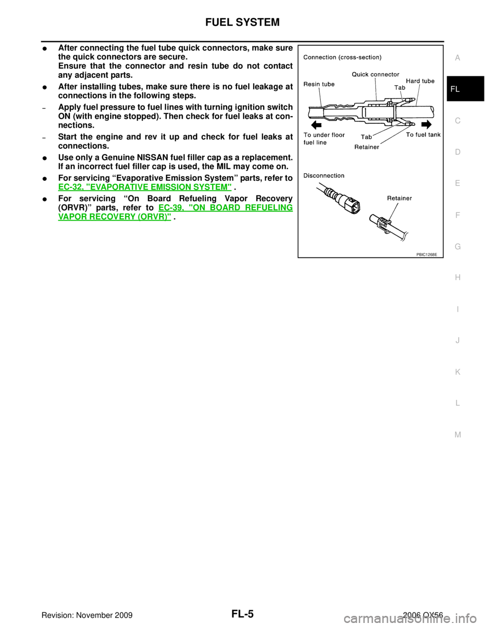
�After connecting the fuel tube quick connectors, make sure
the quick connectors are secure.
Ensure that the connector and resin tube do not contact
any adjacent parts.
�After installing tubes, make sure there is no fuel leakage at
connections in the following steps.
–Apply fuel pressure to fuel lines with turning ignition switch
ON (with engine stopped). Then check for fuel leaks at con-
nections.
–Start the engine and rev it up and check for fuel leaks at
connections.
�Use only a Genuine NISSAN fuel filler cap as a replacement.
If an incorrect fuel filler cap is used, the MIL may come on.
�For servicing “Evaporative Emission System” parts, refer to
EC-32, "
EVAPORATIVE EMISSION SYSTEM" .
�For servicing “On Board Refueling Vapor Recovery
(ORVR)” parts, refer to EC-39, "
ON BOARD REFUELING
VAPOR RECOVERY (ORVR)" .
PBIC1268E
Page 2064 of 3383

FUEL LEVEL SENSOR UNIT, FUEL FILTER AND FUEL PUMP ASSEMBLYFL-9
C
DE
F
G H
I
J
K L
M A
FL
Revision: November 2009 2006 QX56
12. Remove the lock ring using Tool.
13. Remove the fuel level sensor, fuel filter, and fuel pump assem-
bly. Remove and discard the fuel level sensor, fuel filter, and fuel
pump assembly O-ring.
CAUTION:
�Do not bend the float arm during removal.
�Avoid impacts such as dropping when handling the com-
ponents.
INSTALLATION
Installation is in the reverse order of removal.
�For installation, use a new fuel level sensor, fuel filter, and fuel pump assembly O-ring.
�Connect the quick connector as follows:
–Check the connection for any damage or foreign materials.
–Align the connector with the pipe, then insert the connector straight into the pipe until a click is heard.
–After connecting the quick connector, make sure that the con-
nection is secure by checking as follows:
–Pull the tube and the connector to make sure they are securely
connected.
–Visually inspect the connector to make sure the two retainer tabs
are securely connected.
INSPECTION AFTER INSTALLATION
1. Turn the ignition switch ON but do not start engine, then check the fuel pipes and hose connections forleaks while applying fuel pressure to the system.
2. Start the engine and rev it above idle speed, then check that there are no fuel leaks at any of the fuel pipe and hose connections.Tool number : — (J-46536)
LBIA0389E
PBIC1653E
Page 2069 of 3383

FL-14Revision: November 2009
FUEL TANK
2006 QX56
22. If necessary, remove the lock ring using Tool.
23. If necessary, remove the fuel level sensor, fuel filter, and fuelpump assembly. Discard the fuel level sensor, fuel filter, and fuel
pump assembly O-ring.
CAUTION:
�Do not bend the float arm during removal.
�Avoid impacts such as dropping when handling the com-
ponents.
INSTALLATION
Installation is in the reverse order of removal.
�For installation, use a new fuel level sensor, fuel filter, and fuel pump assembly O-ring.
�Connect the quick connector as follows:
–Check the connection for any damage or foreign materials.
–Align the connector with the pipe, then insert the connector straight into the pipe until a click is heard.
–After connecting the quick connector, make sure that the con-
nection is secure by checking as follows:
–Pull the tube and the connector to make sure they are securely
connected.
–Visually inspect the connector to make sure the two retainer tabs
are securely connected.
INSPECTION AFTER INSTALLATION
1. Turn the ignition switch ON but do not start engine, then check the fuel pipe and hose connections forleaks while applying fuel pressure.
2. Start the engine and rev it above idle, then check that there are no fuel leaks at any of the fuel pipe and hose connections.Tool number : — (J-46536)
LBIA0389E
PBIC1653E