Page 1366 of 3383

DTC U1010 CAN COMMUNICATIONEC-155
C
DE
F
G H
I
J
K L
M A
EC
Revision: November 2009 2006 QX56
Diagnostic ProcedureUBS00N8X
1. INSPECTION START
With CONSULT-II
1. Turn ignition switch ON.
2. Select “SELF-DIAG RESULTS ” mode with CONSULT-II.
3. Touch “ERASE”.
4. Perform DTC Confirmation Procedure.
See EC-154, "
DTC Confirmation Procedure" .
5. Is the DTC U1010 displayed again?
With GST
1. Turn ignition switch ON.
2. Select Service $04 with GST.
3. Perform DTC Confirmation Procedure.
See EC-154, "
DTC Confirmation Procedure" .
4. Is the DTC U1010 displayed again?
Ye s o r N o
Ye s > > G O T O 2 .
No >> INSPECTION END
2. REPLACE ECM
1. Replace ECM.
2. Perform initialization of IVIS (NATS) system and registration of all IVIS (NATS) ignition key IDs. Refer to BL-139, "
ECM Re-communicating Function" .
3. Perform EC-77, "
VIN Registration" .
4. Perform EC-78, "
Accelerator Pedal Released Position Learning" .
5. Perform EC-78, "
Throttle Valve Closed Position Learning" .
6. Perform EC-78, "
Idle Air Volume Learning" .
>> INSPECTION END
Page 1656 of 3383
DTC P0506 ISC SYSTEMEC-445
C
DE
F
G H
I
J
K L
M A
EC
Revision: November 2009 2006 QX56
Diagnostic ProcedureUBS00H6K
1. CHECK INTAKE AIR LEAK
1. Start engine and let it idle.
2. Listen for an intake air leak after the mass air flow sensor.
OK or NG
OK >> GO TO 2.
NG >> Discover air leak location and repair.
2. REPLACE ECM
1. Stop engine.
2. Replace ECM.
3. Perform initialization of IVIS(NATS) system and registration of all IVIS(NATS) ignition key IDs. Refer to BL-139, "
ECM Re-communicating Function" .
4. Perform EC-77, "
VIN Registration" .
5. Perform EC-78, "
Accelerator Pedal Released Position Learning" .
6. Perform EC-78, "
Throttle Valve Closed Position Learning" .
7. Perform EC-78, "
Idle Air Volume Learning" .
>> INSPECTION END
Page 1658 of 3383
DTC P0507 ISC SYSTEMEC-447
C
DE
F
G H
I
J
K L
M A
EC
Revision: November 2009 2006 QX56
Diagnostic ProcedureUBS00H6O
1. CHECK PCV HOSE CONNECTION
Confirm that PCV hose is connected correctly.
OK or NG
OK >> GO TO 2.
NG >> Repair or replace.
2. CHECK INTAKE AIR LEAK
1. Start engine and let it idle.
2. Listen for an intake air leak after the mass air flow sensor.
OK or NG
OK >> GO TO 3.
NG >> Discover air leak location and repair.
3. REPLACE ECM
1. Stop engine.
2. Replace ECM.
3. Perform initialization of IVIS(NATS) system and registration of all IVIS(NATS) ignition key IDs. Refer to BL-139, "
ECM Re-communicating Function" .
4. Perform EC-77, "
VIN Registration" .
5. Perform EC-78, "
Accelerator Pedal Released Position Learning" .
6. Perform EC-78, "
Throttle Valve Closed Position Learning" .
7. Perform EC-78, "
Idle Air Volume Learning" .
>> INSPECTION END
Page 1667 of 3383

EC-456Revision: November 2009
DTC P0603 ECM POWER SUPPLY
2006 QX56
4. PERFORM DTC CONFIRMATION PROCEDURE
With CONSULT-II
1. Turn ignition switch ON.
2. Select “SELF DIAG RESULTS ” mode with CONSULT-II.
3. Touch “ERASE”.
4. Perform DTC Confirmation Procedure.
See EC-453, "
DTC Confirmation Procedure" .
5. Is the 1st trip DTC P0603 displayed again?
With GST
1. Turn ignition switch ON.
2. Select Service $04 with GST.
3. Perform DTC Confirmation Procedure.
See EC-453, "
DTC Confirmation Procedure" .
4. Is the 1st trip DTC P0603 displayed again?
Ye s o r N o
Yes >> GO TO 5.
No >> INSPECTION END
5. REPLACE ECM
1. Replace ECM.
2. Perform initialization of IVIS(NATS) system and registration of all IVIS(NATS) ignition key IDs. Refer to BL-139, "
ECM Re-communicating Function" .
3. Perform EC-77, "
VIN Registration" .
4. Perform EC-78, "
Accelerator Pedal Released Position Learning" .
5. Perform EC-78, "
Throttle Valve Closed Position Learning" .
6. Perform EC-78, "
Idle Air Volume Learning" .
>> INSPECTION END
Page 1670 of 3383
DTC P0605 ECMEC-459
C
DE
F
G H
I
J
K L
M A
EC
Revision: November 2009 2006 QX56
2. REPLACE ECM
1. Replace ECM.
2. Perform initialization of IVIS(NATS) system and registration of all IVIS(NATS) ignition key IDs. Refer to BL-139, "
ECM Re-communicating Function" .
3. Perform EC-77, "
VIN Registration" .
4. Perform EC-78, "
Accelerator Pedal Released Position Learning" .
5. Perform EC-78, "
Throttle Valve Closed Position Learning" .
6. Perform EC-78, "
Idle Air Volume Learning" .
>> INSPECTION END
Page 1932 of 3383

TIMING CHAINEM-41
C
DE
F
G H
I
J
K L
M A
EM
Revision: November 2009 2006 QX56
INSTALLATION
NOTE:
�The above figure shows the relationship between the mating mark on each timing chain and that of the
corresponding sprocket, with the components installed.
�To install the timing chain and associated parts, start with those on the RH bank. The procedure for install-
ing parts on the LH bank is omitted because it is the same as that for installation on the RH bank.
WBIA0699E
1. RH bank Camshaft sprocket (Intake) 2.RH bank Camshaft sprocket
(Exhaust)3. RH bank camshaft dowel pin
4. Timing chain 5. RH bank Timing chain slack guide 6. Primary timing chain tensioner
7. Crankshaft sprocket 8. Crankshaft key9. LH Timing chain tension guide
10. Timing chain 11. LH Camshaft dowel pin 12. LH Camshaft sprocket (Exhaust)
13. LH Camshaft sprocket (Intake) 14. Secondary timing chain tensioner 15. RH bank timing chain tension guide
16. LH timing chain slack guide A. LH bank B. RH bank
C. Alignment mark (Link color: copper) D. Alignment mark (Link color: copper) E. Alignment mark (Identification mark)
F. Alignment mark for LH bank (Notch) G. Alignment mark for LH bank (Link
color: Yellow or Gold)H. Alignment mark for RH bank (Notch)
J. Alignment mark (Link color: copper) K. Alignment mark (Identification mark) L. Alignment mark (Identification mark)
M Alignment mark (Link color: copper) N. Alignment mark (Identification mark)
Page 1933 of 3383

EM-42Revision: November 2009
TIMING CHAIN
2006 QX56
1. Make sure the crankshaft key and RH bank camshaft dowel pinand LH bank camshaft dowel pin are facing in the direction
shown.
2. Install the camshaft sprockets.
�Install the intake camshaft sprocket and exhaust camshaft
sprockets by selectively using the groove of the dowel pin
according to the bank. (Common part used for both banks.)
�Lock the hexagonal part of the camshaft in the same way as
for removal, and tighten the bolts.
�A = I: Intake
�B = E: Exhaust
3. Install the crankshaft sprockets for both banks.
�Install LH bank crankshaft sprocket (B) and RH bank crank-
shaft sprocket (C) so that their flange side (A) (the larger
diameter side without teeth) faces in the direction shown.
NOTE:
The same parts are used but facing directions are different.
4. Install the timing chains and associated parts.
�Align the alignment mark on each sprocket and the timing chain for installation.
CAUTION:
�Before installing timing chain tensioner, it is possible to change the position of alignment
mark on timing chain and each sprocket. After the alignment marks are aligned, keep them
aligned by holding them by hand.
�Install the slack guides and tension guides onto the correct side by checking the identification mark on
the surface.
�Install the timing chain tensioner with the plunger locked in with the stopper pin.
CAUTION:
�Before and after the installation of the timing chain tensioner, make sure that the alignment
mark on the timing chain is not out of alignment.
�After installing the timing chain tensioner, remove the stopper pin to release the tensioner.
Make sure the tensioner is released.
�To avoid chain-link skipping of the timing chain, do not move crankshaft or camshafts until
the front cover is installed.
5. In the same way as for the RH bank, install the timing chain and associated parts on the LH bank.
6. Install the oil pump.
SBIA0356E
WBIA0700E
WBIA0701E
Page 1934 of 3383
TIMING CHAINEM-43
C
DE
F
G H
I
J
K L
M A
EM
Revision: November 2009 2006 QX56
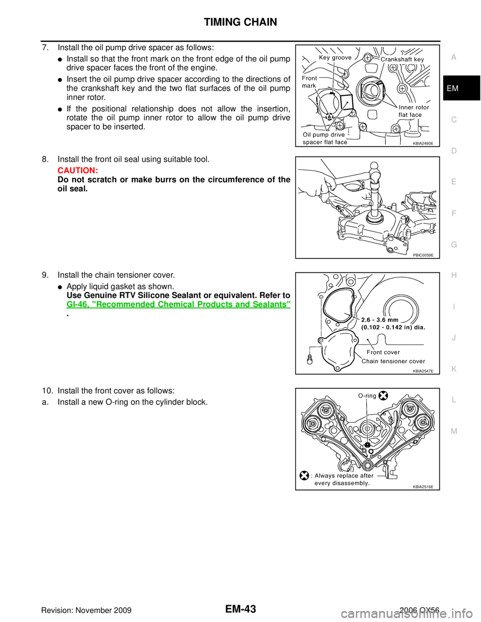
7. Install the oil pump drive spacer as follows:
�Install so that the front mark on the front edge of the oil pump
drive spacer faces the front of the engine.
�Insert the oil pump drive spacer according to the directions of
the crankshaft key and the two flat surfaces of the oil pump
inner rotor.
�If the positional relationship does not allow the insertion,
rotate the oil pump inner rotor to allow the oil pump drive
spacer to be inserted.
8. Install the front oil seal using suitable tool. CAUTION:
Do not scratch or make burrs on the circumference of the
oil seal.
9. Install the chain tensioner cover.
�Apply liquid gasket as shown.
Use Genuine RTV Silicone Sealant or equivalent. Refer to
GI-46, "
Recommended Chemical Products and Sealants"
.
10. Install the front cover as follows:
a. Install a new O-ring on the cylinder block.
KBIA2490E
PBIC0059E
KBIA2547E
KBIA2516E


 system and registration of all IVIS(NATS) ignitio")