IPDM E/R (INTELLIGENT POWER DISTRIBUTION MODULE ENGINE ROOM)PG-25
C
DE
F
G H
I
J
L
M A
B
PG
Revision: November 2009 2006 QX56
Concept of Auto Active Test
�IPDM E/R actuates auto active test mode when it receives door switch signal from BCM via CAN commu-
nication line. Therefore, when auto active test mode is activated successfully, CAN communication
between IPDM E/R and BCM is normal.
�If any of the systems controlled by IPDM E/R cannot be operated, possible cause can be easily diagnosed
using auto active test.
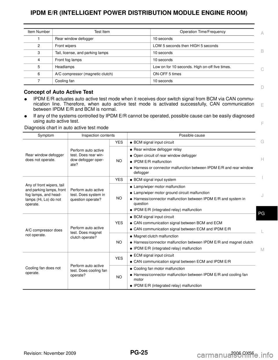
Diagnosis chart in auto active test mode
Item Number Test Item Operation Time/Frequency
1 Rear window defogger 10 seconds
2 Front wipers LOW 5 seconds then HIGH 5 seconds
3 Tail, license, and parking lamps 10 seconds
4 Front fog lamps 10 seconds
5 Headlamps Low on for 10 seconds. High on-off five times.
6 A/C compressor (magnetic clutch) ON-OFF 5 times
7 Cooling fan 10 seconds
SymptomInspection contents Possible cause
Rear window defogger
does not operate. Perform auto active
test. Does rear win-
dow defogger oper-
ate?YES
�BCM signal input circuit
NO
�Rear window defogger relay
�Open circuit of rear window defogger
�IPDM E/R malfunction
�Harness or connector malfunction between IPDM E/R and rear window
defogger
Any of front wipers, tail
and parking lamps, front
fog lamps, and head-
lamps (Hi, Lo) do not
operate. Perform auto active
test. Does system in
question operate?YES
�BCM signal input system
NO
�Lamp/wiper motor malfunction
�Lamp/wiper motor ground circuit malfunction
�Harness/connector malfunction between IPDM E/R and system in
question
�IPDM E/R (integrated relay) malfunction
A/C compressor does
not operate. Perform auto active
test. Does magnet
clutch operate?YES
�BCM signal input circuit
�CAN communication signal between BCM and ECM
�CAN communication signal between ECM and IPDM E/R
NO
�Magnet clutch malfunction
�Harness/connector malfunction between IPDM E/R and magnet clutch
�IPDM E/R (integrated relay) malfunction
Cooling fan does not
operate. Perform auto active
test. Does cooling fan
operate?YES
�ECM signal input circuit
�CAN communication signal between ECM and IPDM E/R
NO
�Cooling fan motor malfunction
�Harness/connector malfunction between IPDM E/R and cooling fan
motor
�IPDM E/R (integrated relay) malfunction
PG-62
HARNESS
Revision: November 20092006 QX56
Wiring Diagram Codes (Cell Codes)EKS00BNE
Use the chart below to find out what each wiring diagram code stands for.
Refer to the wiring diagram code in the alphabetical index to find the location (page number) of each wiring
diagram.
CodeSection Wiring Diagram Name
A/C,A ATC Auto Air Conditioner
A/SUSP RSU Rear Air Suspension
AF1B1 EC Air Fuel Ratio (A/F) Sensor 1 (Bank 1)
AF1B2 EC Air Fuel Ratio (A/F) Sensor 1 (Bank 2)
AF1HB1 EC Air Fuel Ratio (A/F) Sensor 1 (Bank 1)
AF1HB2 EC Air Fuel Ratio (A/F) Sensor 1 (Bank 2)
APPS1 EC Accelerator Pedal Position Sensor
APPS2 EC Accelerator Pedal Position Sensor
APPS3 EC Accelerator Pedal Position Sensor
ASC/BS EC ASCD Brake Switch
ASC/SW EC ASCD Steering Switch
ASCBOF EC ASCD Brake Switch
ASCIND EC ASCD Indicator
A/T AT A/T Assembly
AT/IND DI A/T Indicator Lamp
AUDIO AV Audio
AUT/DP SE Automatic Drive Positioner
AUTO/L LT Auto Light Control
B/CLOS BL Back Door Auto Closure System
BACK/L LT Back-up Lamp
BRK/SW EC Brake Switch
CAN EC CAN Communication Line
CAN LAN CAN System
CHARGE SC Charging System
CHIME DI Warning Chime
CLOCK DI Clock
COOL/F EC Cooling Fan Control
COMBSW LT Combination Switch
COMM AV Audio Visual Communication System
COMPAS DI Compass and Thermometer
D/LOCK BL Power Door Lock
DEF GW Rear Window Defogger
DTRL LT Headlamp - With Daytime Light System
DVD AV DVD Entertainment System
ECM/PW EC ECM Power Supply for Back-Up
ECTS EC Engine Coolant Temperature Sensor
ETC1 EC Electric Throttle Control Function
ETC2 EC Throttle Control Motor Relay
ETC3 EC Throttle Control Motor
F/FOG LT Front Fog Lamp
F/PUMP EC Fuel Pump
FTTS EC Fuel Tank Temperature Sensor
FUELB1 EC Fuel Injection System Bank 1
FUELB2 EC Fuel Injection System Bank 2
H/AIM LT Headlamp Aiming Control
H/PHON AV Hands Free Telephone
H/LAMP LT Headlamp
EKS00BNE
Use the chart below to find out what each wiring diagram code stands for.
Refer to the wiring diagram code in t")