Page 2015 of 3383

FAX-6
WHEEL HUB
Revision: November 20092006 QX56
4. Put alignment mark on disc rotor and wheel hub and bearing
assembly, then remove disc rotor.
5. On 4WD model, remove cotter pin, then remove lock nut from drive shaft using power tool. Then remove end of drive shaft from wheel hub and bearing assembly. Refer to FA X - 7 , "
Removal and Installation" .
6. Remove wheel sensor. Refer to BRC-64, "
Removal and Installation" .
�Inspect the wheel sensor O-ring, replace the wheel sensor assembly if damaged.
�Clean the wheel sensor hole and mounting surface with a suitable brake cleaner and clean lint-free
shop rag. Be careful that dirt and debris do not enter the axle bearing area.
�Apply a coat of suitable grease to the wheel sensor O-ring and mounting hole.
CAUTION:
Do not pull on the wheel sensor harness.
7. Remove wheel hub and bearing assembly bolts using power tool.
8. Remove splash guard and wheel hub and bearing assembly from steering knuckle.
INSPECTION AFTER REMOVAL
Check for deformity, cracks and damage on each part, replace if necessary.
INSTALLATION
Installation is in the reverse order of removal.
�Use new bolts when installing the wheel hub and bearing assembly.
�When installing disc rotor on wheel hub and bearing assembly,
position the disc rotor according to alignment mark.
(When not using the alignment mark, refer to BR-25, "
DISC
ROTOR INSPECTION" .)
�When installing wheel and tire. Refer to WT-7, "Rotation" .
WDIA0044E
WDIA0044E
Page 2016 of 3383

DRIVE SHAFTFAX-7
CE F
G H
I
J
K L
M A
B
FA X
Revision: November 2009 2006 QX56
DRIVE SHAFTPFP:39100
Removal and InstallationEDS003BP
REMOVAL
1. Remove wheel and tire using power tool.
2. Remove engine under cover using power tool.
3. Remove wheel sensor harness from mount on knuckle.
CAUTION:
Do not pull on wheel sensor harness.
4. Without disassembling the hydraulic lines, remove brake caliper using power tool. Reposition it aside with wire. Refer to BR-22, "
Removal and Installation of Brake Caliper and Disc Rotor" .
NOTE:
Avoid depressing brake pedal while brake caliper is removed.
5. Remove coil spring and shock absorber assembly using power tool. Refer to FSU-10, "
Removal and
Installation" .
6. Separate upper link ball joint stud from steering knuckle using To o l .
�Support lower link with jack.
7. Remove cotter pin, then remove drive shaft nut.
8. Remove drive shaft mounting bolts from front final drive.
9. Remove drive shaft from wheel hub and bearing assembly. CAUTION:
�When removing drive shaft, do not apply an excessive
angle to drive shaft joint. Also be careful not to exces-
sively extend slide joint.
INSPECTION AFTER REMOVAL
�Move joint up, down, left, right, and in axial direction. Check for any rough movement or significant loose-
ness.
�Check boot for cracks or other damage, and for grease leakage.
�If damaged, disassemble drive shaft to verify damage, and
repair or replace as necessary.
1. Cotter pin 2. Drive shaft nut3. Drive shaft
WDIA0329E
Tool number : ST29020001 (J-24319-01)
LEIA0095E
RAA0030D
Page 2017 of 3383
FAX-8
DRIVE SHAFT
Revision: November 20092006 QX56
INSTALLATION
Installation is in the reverse order of removal.
�Tighten wheel nuts to specification. Refer to WT-7, "Rotation" .
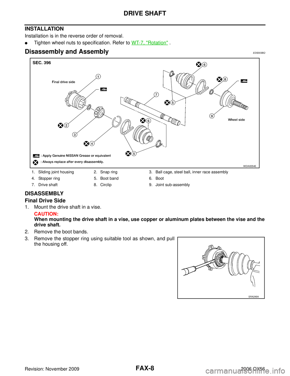
Disassembly and AssemblyEDS003BQ
DISASSEMBLY
Final Drive Side
1. Mount the drive shaft in a vise.
CAUTION:
When mounting the drive shaft in a vise, use copper or aluminum plates between the vise and the
drive shaft.
2. Remove the boot bands.
3. Remove the stopper ring using suitable tool as shown, and pull the housing off.
1. Sliding joint housing 2. Snap ring 3. Ball cage, steel ball, inner race assembly
4. Stopper ring 5. Boot band6. Boot
7. Drive shaft 8. Circlip9. Joint sub-assembly
WDIA0054E
SRA249A
Page 2018 of 3383

DRIVE SHAFTFAX-9
CE F
G H
I
J
K L
M A
B
FA X
Revision: November 2009 2006 QX56
4. Remove the snap ring, then remove the ball cage, steel ball,
inner race assembly from the drive shaft.
5. Remove the boot from the drive shaft.
6. Remove any old grease on the housing using paper towels.
Wheel Side
1. Mount the drive shaft in a vise. CAUTION:
When mounting the drive shaft in a vise, use copper or aluminum plates between the vise and the
drive shaft.
2. Remove the boot bands, then remove the boot from the joint sub-assembly.
3. Screw a suitable drive shaft puller 30 mm (1.18 in) or more into the threaded part of the joint sub-assembly. Pull the joint sub-
assembly off of the drive shaft as shown.
NOTE:
Align the sliding hammer and drive shaft and remove the joint
sub-assembly by pulling straight out.
CAUTION:
�If the joint sub-assembly cannot be removed after five or
more attempts, replace the drive shaft and joint sub-
assembly as a set.
4. Remove the boot from the drive shaft.
5. Remove the circlip from the drive shaft.
6. While rotating the ball cage, remove any old grease from the joint sub-assembly using paper towels.
INSPECTION AFTER DISASSEMBLY
Drive Shaft
�Replace the drive shaft if there is any runout, cracking, or other damage.
Joint Sub-assembly
�Check for any rough rotation or unusual axial looseness.
�Clean any foreign material from inside the joint sub-assembly.
�Check for any compression scars, cracks, or fractures.
CAUTION:
If any defective conditions are found in the joint sub-assembly components, replace the entire
joint sub-assembly.
Sliding Joint Side Housing
�Check for any compression scars, cracks, fractures, or unusual wear on the ball rolling surface.
�Check for any damage to the drive shaft screws.
�Check for any deformation of the boot installation components.
Ball Cage
�Check the sliding surface for any compression scars, cracks, or fractures.
SFA514A
SDIA0606E
Page 2020 of 3383

as shown.
CAUTION:
If there is grease on boot mount")
DRIVE SHAFTFAX-11
CE F
G H
I
J
K L
M A
B
FA X
Revision: November 2009 2006 QX56
7. Install the boot securely into the grooves (indicated by * marks)
as shown.
CAUTION:
If there is grease on boot mounting surfaces (indicated by *
marks) of shaft and housing, boot may come off. Remove
all grease from surfaces.
8. Check that the boot installation length “L” is the length indicated below. Insert a suitable tool into the large end of the boot, as
shown. Bleed air from the boot to prevent boot deformation.
CAUTION:
�The boot may break if the boot installation length is less than the specified value.
�Do not contact inside surface of boot with tip of the suitable tool.
9. Secure the large and small ends of the boot with the new boot bands as shown.
NOTE:
Discard the old boot bands and use new ones for assembly.
10. After installing the sliding joint housing to the drive shaft, rotate the boot to check that the boot is posi- tioned correctly. If the boot is not positioned correctly, reposition the boot and secure the boot using a new
boot band.
Wheel Side
1. Insert the Genuine NISSAN Grease or equivalent, into the jointsub-assembly serration hole until the grease begins to ooze
from the ball groove and serration hole. Refer to MA-11, "
REC-
OMMENDED FLUIDS AND LUBRICANTS" . After inserting the
grease, use a shop cloth to wipe off the grease that has oozed
out.
2. Wrap the serrated part of the drive shaft with tape. Install the boot band and boot onto the shaft. Do not damage the boot.
NOTE:
Discard the old boot band and boot and use a new one for
assembly.
3. Remove the protective tape wound around the serrated part of the drive shaft. Boot installation length “L ” : 145 mm (5.71 in)
WDIA0287E
SFA395
SDIA1127E
SFA800
Page 2022 of 3383
SERVICE DATA AND SPECIFICATIONS (SDS)FAX-13
CE F
G H
I
J
K L
M A
B
FA X
Revision: November 2009 2006 QX56
SERVICE DATA AND SPECIFICATIONS (SDS)PFP:00030
Wheel BearingEDS003BR
Drive ShaftEDS003BS
Boot BandsEDS004G1
Unit: mm (in)
Wheel bearing axial end play
0.05 mm (0.002 in) or less
Drive shaft joint typeFinal drive side Rzeppa
Wheel side Rzeppa
Grease Quality
Nissan Genuine Grease or
equivalent
Capacity Final drive side
130 - 150 g (4.58 - 5.29 oz)
Wheel side 145 - 165 g (5.11 - 5.82 oz)
Boot length Final drive side "L "
145 mm (5.71 in)
Wheel side "L " 168.4 mm (6.63 in)
WDIA0055E
Dimension "M" 1.0 - 4.0 (0.039 - 0.157)
DSF0047D
Page 2029 of 3383
FFD-6
NOISE, VIBRATION AND HARSHNESS (NVH) TROUBLESHOOTING
Revision: November 20092006 QX56
NOISE, VIBRATION AND HARSHNESS (NVH) TROUBLESHOOTINGPFP:00003
NVH Troubleshooting ChartEDS00450
Use the chart below to help you find the cause of the symptom. If necessary, repair or replace these parts.
×: ApplicableReference page
FFD-23FFD-16FFD-16FFD-17FFD-17FFD-7
PR-3, "
NVH Troubleshooting Chart
"
FAX-4, "
NVH Troubleshooting Chart
"
FSU-4, "
NVH Troubleshooting Chart
"
WT-4, "
NVH Troubleshooting Chart
"
WT-4, "
NVH Troubleshooting Chart
"
FAX-4, "
NVH Troubleshooting Chart
"
BR-5, "
NVH Troubleshooting Chart
"
PS-5, "
NVH Troubleshooting Chart
"
Possible cause and SUSPECTED PARTS
Gear tooth rough
Gear contact improper
Tooth surfaces worn
Incorrect backlash
Companion flange excessive runout
Gear oil improper
PROPELLER SHAFT
FRONT AXLE
FRONT SUSPENSION
TIRES
ROAD WHEEL
DRIVE SHAFT
BRAKES
STEERING
Symptom
Noise××××××××××××××
Page 2061 of 3383

FL-6Revision: November 2009
FUEL LEVEL SENSOR UNIT, FUEL FILTER AND FUEL PUMP ASSEMBLY
2006 QX56
FUEL LEVEL SENSOR UNIT, FUEL FILTER AND FUEL PUMP ASSEMBLYPFP:17042
Removal and InstallationEBS00M3S
REMOVAL
WARNING:
Follow the “General Precautions” before working on the fuel system. Refer to FL-4, "
General Precau-
tions" .
1. Remove the fuel filler cap to release the pressure from inside the fuel tank.
2. Check the fuel level on level gauge. If the fuel gauge indicates more than the level as shown (full or almost full), drain the fuel
from the fuel tank until the fuel gauge indicates the level as
shown, or less.
�If the fuel pump does not operate, use the following procedure
to drain the fuel to the specified level.
a. Insert a suitable hose of less than 15 mm (0.59 in) diameter into the fuel filler pipe through the fuel filler opening to drain the fuel
from fuel filler pipe.
b. Remove the LH rear wheel and tire. Refer to WT-7, "
Rotation" .
c. Remove the four clips and remove the rear fender protector, front.
1. Inspection hole cover 2. Inspection hole cover O-ring 3. Lock ring
4. Fuel level sensor, fuel filter, and fuel pump assembly 5. Fuel tank
6. Fuel level sensor, fuel filter, and fuel
pump assembly O-ring
LBIA0381E
WBIA0390E
FAX-13
CE F
G H
I
J
K L
M A
B
FA X
Revision: November 2009 2006 QX56
SERVICE DATA AND SPECIFICATIONS (SDS)PFP:00030
Wheel BearingEDS003BR
Drive ShaftEDS003BS
Boot")
 TROUBLESHOOTING
Revision: November 20092006 QX56
NOISE, VIBRATION AND HARSHNESS (NVH) TROUBLESHOOTINGPFP:00003
NVH Troubleshooting ChartEDS00450
Use the char")