Page 3296 of 3383

WHEEL AND TIRE ASSEMBLYWT-7
C
DF
G H
I
J
K L
M A
B
WT
Revision: November 2009 2006 QX56
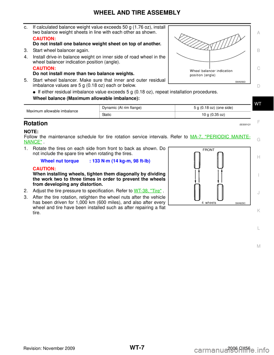
c. If calculated balance weight value exceeds 50 g (1.76 oz), install
two balance weight sheets in line with each other as shown.
CAUTION:
Do not install one balance weight sheet on top of another.
3. Start wheel balancer again.
4. Install drive-in balance weight on inner side of road wheel in the wheel balancer indication position (angle).
CAUTION:
Do not install more than two balance weights.
5. Start wheel balancer. Make sure that inner and outer residual imbalance values are 5 g (0.18 oz) each or below.
�If either residual imbalance value exceeds 5 g (0.18 oz), repeat installation procedures.
Wheel balance (Maximum allowable imbalance):
RotationEES001Q1
NOTE:
Follow the maintenance schedule for tire rotation service intervals. Refer to MA-7, "
PERIODIC MAINTE-
NANCE" .
1. Rotate the tires on each side from front to back as shown. Do not include the spare tire when rotating the tires.
CAUTION:
When installing wheels, tighten them diagonally by dividing
the work two to three times in order to prevent the wheels
from developing any distortion.
2. Adjust the tire pressure to specification. Refer to WT-38, "
Tire" .
3. After the tire rotation, retighten the wheel nuts after the vehicle has been driven for 1,000 km (600 miles), and also after every
wheel and tire have been installed such as after repairing a flat
tire.
Maximum allowable imbalance Dynamic (At rim flange)
5 g (0.18 oz) (one side)
Static 10 g (0.35 oz)
SMA056D
Wheel nut torque : 133 N·m (14 kg-m, 98 ft-lb)
SMA829C
Page 3297 of 3383
WT-8
LOW TIRE PRESSURE WARNING SYSTEM
Revision: November 20092006 QX56
LOW TIRE PRESSURE WARNING SYSTEMPFP:40300
System ComponentsEES001I2
System DescriptionEES001I3
TRANSMITTER
A sensor-transmitter integrated with a valve is installed on a wheel,
and transmits a detected air pressure signal in the form of a radio
wave.
REMOTE KEYLESS ENTRY RECEIVER
Receives the air pressure signal transmitted by the transmitter in
each wheel.
WEIA0081E
WEIA0137E
LEIA0069E
Page 3298 of 3383

LOW TIRE PRESSURE WARNING SYSTEMWT-9
C
DF
G H
I
J
K L
M A
B
WT
Revision: November 2009 2006 QX56
BCM (BODY CONTROL MODULE)
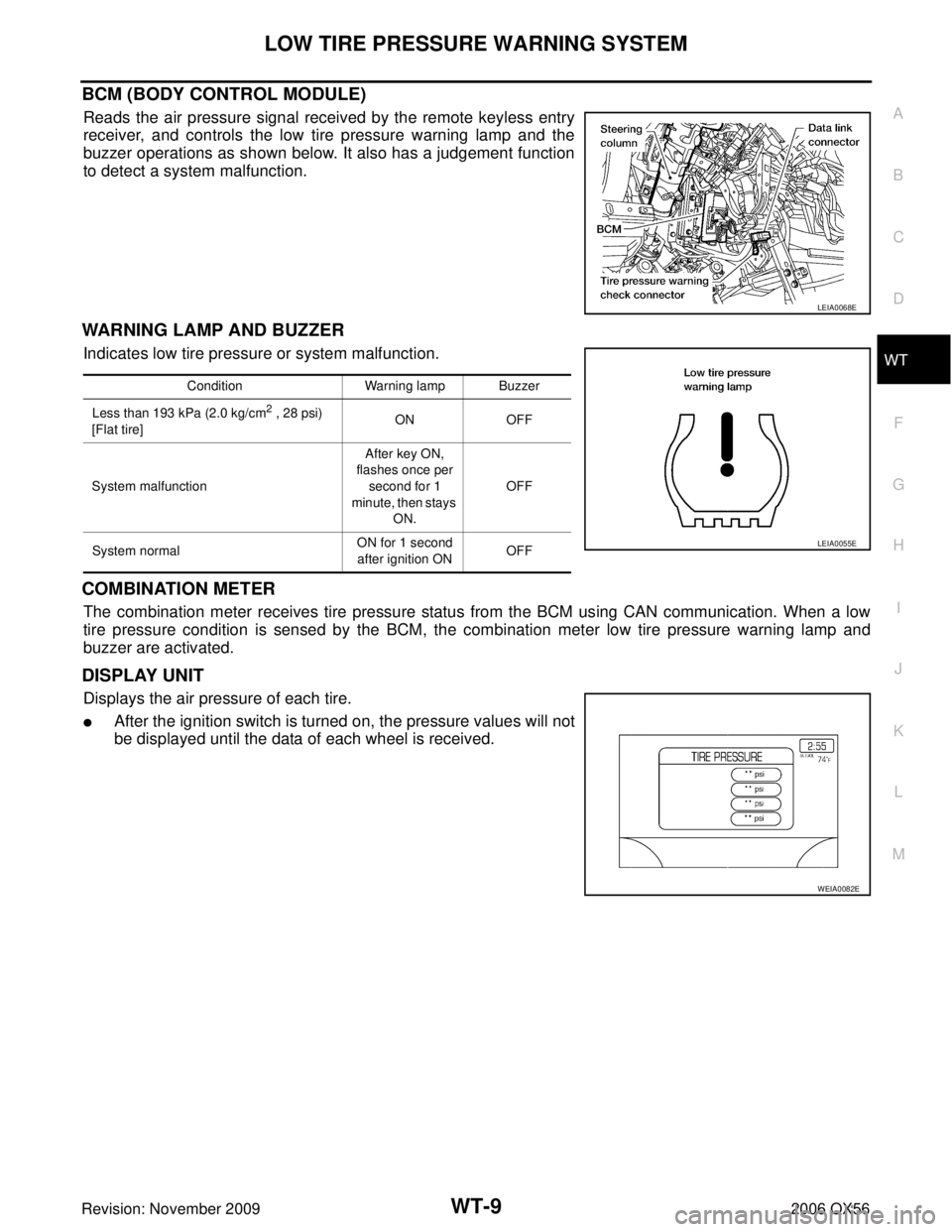
Reads the air pressure signal received by the remote keyless entry
receiver, and controls the low tire pressure warning lamp and the
buzzer operations as shown below. It also has a judgement function
to detect a system malfunction.
WARNING LAMP AND BUZZER
Indicates low tire pressure or system malfunction.
COMBINATION METER
The combination meter receives tire pressure status from the BCM using CAN communication. When a low
tire pressure condition is sensed by the BCM, the combination meter low tire pressure warning lamp and
buzzer are activated.
DISPLAY UNIT
Displays the air pressure of each tire.
�After the ignition switch is turned on, the pressure values will not
be displayed until the data of each wheel is received.
LEIA0068E
ConditionWarning lamp Buzzer
Less than 193 kPa (2.0 kg/cm
2 , 28 psi)
[Flat tire] ON
OFF
System malfunction After key ON,
flashes once per second for 1
minute, then stays ON. OFF
System normal ON for 1 second
after ignition ON OFF
LEIA0055E
WEIA0082E
Page 3304 of 3383
TROUBLE DIAGNOSESWT-15
C
DF
G H
I
J
K L
M A
B
WT
Revision: November 2009 2006 QX56
6. Push the transmitter activation tool against the tire near the front
left transmitter. Press the button for 5 seconds.
7. Register the IDs in order from FR LH, FR RH, RR RH and RR LH. When ID registration of each wheel has been completed, a buzzer sounds and the hazard warning lamps flash.
8. After completing all ID registrations, press “END” to complete the procedure.
NOTE:
Be sure to register the IDs in order from FR LH, FR RH, RR RH, to RR LH, or the self-diagnostic results dis-
play will not function properly. Tool number : (J-45295)
SEIA0101E
Activation tire position
BuzzerHazard warning lamp CONSULT-II
1 Front LH Once
2 times flashing “
YET ”
↓
“ DONE ”
2F
ro n t R H 2 tim es
3R ear R H 3 tim es
4 Rear LH 4 times
Page 3309 of 3383

WT-20
TROUBLE DIAGNOSES
Revision: November 20092006 QX56
Self-DiagnosisEES001I9
DESCRIPTION
During driving, the low tire pressure warning system receives the signal transmitted from the transmitter
installed in each wheel, and gives alarms when the tire pressure becomes low. The control unit (BCM) for this
system has pressure judgement and trouble diagnosis functions.
FUNCTION
When the low tire pressure warning system detects low inflation pressure or another unusual symptom, the
warning lamp in the combination meter comes on. To start the self-diagnostic results mode, ground the tire
pressure warning check terminal. The malfunction location is indicated by the low tire pressure warning lamp
flashing and the buzzer sounds.
CONSULT-II
CONSULT-II Application to Low Tire Pressure Warning System
× : Applicable
– : Not applicable
Self-Diagnostic Results Mode
NOTE:
Before performing the self-diagnosis, be sure to register the ID or the actual malfunction location may be different from that displayed on
CONSULT-II. ITEM
SELF-DIAGNOSTIC RESULTS DATA MONITOR
Front - Left transmitter ××
Front - Right transmitter ××
Rear - Left transmitter ××
Rear - Right transmitter ××
Warning lamp —×
Vehicle speed ××
Buzzer (in combination meter) —×
CAN Communication ××
Diagnostic itemDiagnostic item is detected when ···
FLAT - TIRE - FL [C1704]
FLAT - TIRE - FR [C1705]
FLAT - TIRE - RR [C1706]
FLAT - TIRE - RL [C1707] Front-left tire pressure drops to 193 kPa (2.0 kg/cm
2 , 28 psi) or less
Front-right tire pressure drops to 193 kPa (2.0 kg/cm2 , 28 psi) or less
Rear-right tire pressure drops to 193 kPa (2.0 kg/cm2 , 28 psi) or less
Rear-left tire pressure drops to 193 kPa (2.0 kg/cm2 , 28 psi) or less
[NO-DATA] - FL [C1708]
[NO-DATA] - FR [C1709]
[NO-DATA] - RR [C1710]
[NO-DATA] - RL [C1711] Data from front-left transmitter cannot be received.
Data from front-right transmitter cannot be received.
Data from rear-right transmitter cannot be received.
Data from rear-left transmitter cannot be received.
[CHECKSUM- ERR] - FL
[CHECKSUM- ERR] - FR
[CHECKSUM- ERR] - RR
[CHECKSUM- ERR] - RL Checksum data from front-left transmitter is malfunctioning.
Checksum data from front-right transmitter is malfunctioning.
Checksum data from rear-right transmitter is malfunctioning.
Checksum data from rear-left transmitter is malfunctioning.
[PRESSDATA- ERR] - FL
[PRESSDATA- ERR] - FR
[PRESSDATA- ERR] - RR
[PRESSDATA- ERR] - RL Air pressure data from front-left transmitter is malfunctioning.
Air pressure data from front-right transmitter is malfunctioning.
Air pressure data from rear-right transmitter is malfunctioning.
Air pressure data from rear-left transmitter is malfunctioning.
[CODE- ERR] - FL
[CODE- ERR] - FR
[CODE- ERR] - RR
[CODE- ERR] - RL Function code data from front-left transmitter is malfunctioning.
Function code data from front-right transmitter is malfunctioning.
Function code data from rear-right transmitter is malfunctioning.
Function code data from rear-left transmitter is malfunctioning.
[BATT - VOLT - LOW] - FL
[BATT - VOLT - LOW] - FR
[BATT - VOLT - LOW] - RR
[BATT - VOLT - LOW] - RL Battery voltage of front-left transmitter drops.
Battery voltage of front-right transmitter drops.
Battery voltage of rear-right transmitter drops.
Battery voltage of rear-left transmitter drops.
VHCL_SPEED_SIG_ERR [C1729] Vehicle speed signal is in error.
Page 3325 of 3383

WT-36
REMOVAL AND INSTALLATION
Revision: November 20092006 QX56
REMOVAL AND INSTALLATIONPFP:00000
Transmitter (Pressure Sensor)EES001IN
REMOVAL
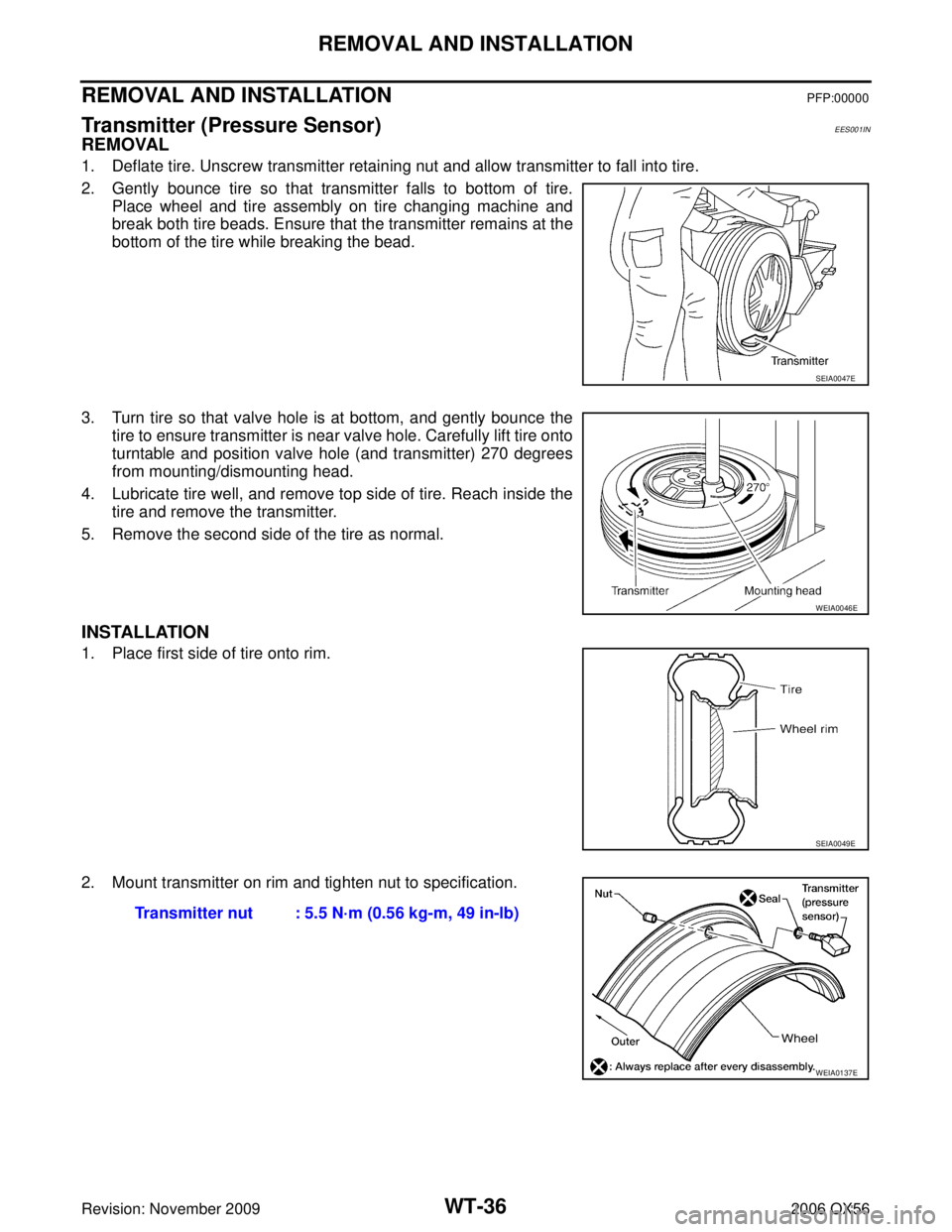
1. Deflate tire. Unscrew transmitter retaining nut and allow transmitter to fall into tire.
2. Gently bounce tire so that transmitter falls to bottom of tire.
Place wheel and tire assembly on tire changing machine and
break both tire beads. Ensure that the transmitter remains at the
bottom of the tire while breaking the bead.
3. Turn tire so that valve hole is at bottom, and gently bounce the tire to ensure transmitter is near valve hole. Carefully lift tire onto
turntable and position valve hole (and transmitter) 270 degrees
from mounting/dismounting head.
4. Lubricate tire well, and remove top side of tire. Reach inside the tire and remove the transmitter.
5. Remove the second side of the tire as normal.
INSTALLATION
1. Place first side of tire onto rim.
2. Mount transmitter on rim and tighten nut to specification.
SEIA0047E
WEIA0046E
SEIA0049E
Transmitter nut : 5.5 N·m (0.56 kg-m, 49 in-lb)
WEIA0137E
Page 3326 of 3383
REMOVAL AND INSTALLATIONWT-37
C
DF
G H
I
J
K L
M A
B
WT
Revision: November 2009 2006 QX56
3. Place wheel on turntable of tire machine. Ensure that transmitter
is 270 degrees from mounting/dismounting head.
NOTE:
Do not touch transmitter with mounting head.
4. Lubricate tire well, and install second side of tire as normal. Ensure that tire does not rotate relative to rim.
5. Inflate tire and balance the wheel and tire assembly. Refer to WT-6, "
Wheel Balance Adjustment" .
6. Install Wheel and tire assembly in appropriate wheel position on vehicle.
NOTE:
If replacing the transmitter, then transmitter wake up operation must be performed. Refer to WT-18,
"Transmitter Wake Up Operation" .
7. Adjust neutral position of steering angle sensor. Refer to BRC-62, "
Adjustment of Steering Angle Sensor
Neutral Position" .
WEIA0046E
Page 3327 of 3383
WT-38
SERVICE DATA AND SPECIFICATIONS (SDS)
Revision: November 20092006 QX56
SERVICE DATA AND SPECIFICATIONS (SDS)PFP:00030
Road WheelEES001IO
TireEES001IP
Unit: kPa (kg/cm2 , psi)
Wheel type
Aluminum
Maximum radial runout limit Lateral mm (in)
0.3 (0.012) or less
Radial mm (in) 0.3 (0.012) or less
Maximum residual imbalance Dynamic (at rim flange)
Less than 5 g (0.18 oz) (per side)
Static (at rim flange) Less than 10 g (0.35 oz)
Tire size Air pressure
Conventional tire Spare tire
Full size spare tire —240 (2.4, 35)
P265/70R18 240 (2.4, 35)—