Page 1801 of 3383
EC-590Revision: November 2009
ASCD BRAKE SWITCH
2006 QX56
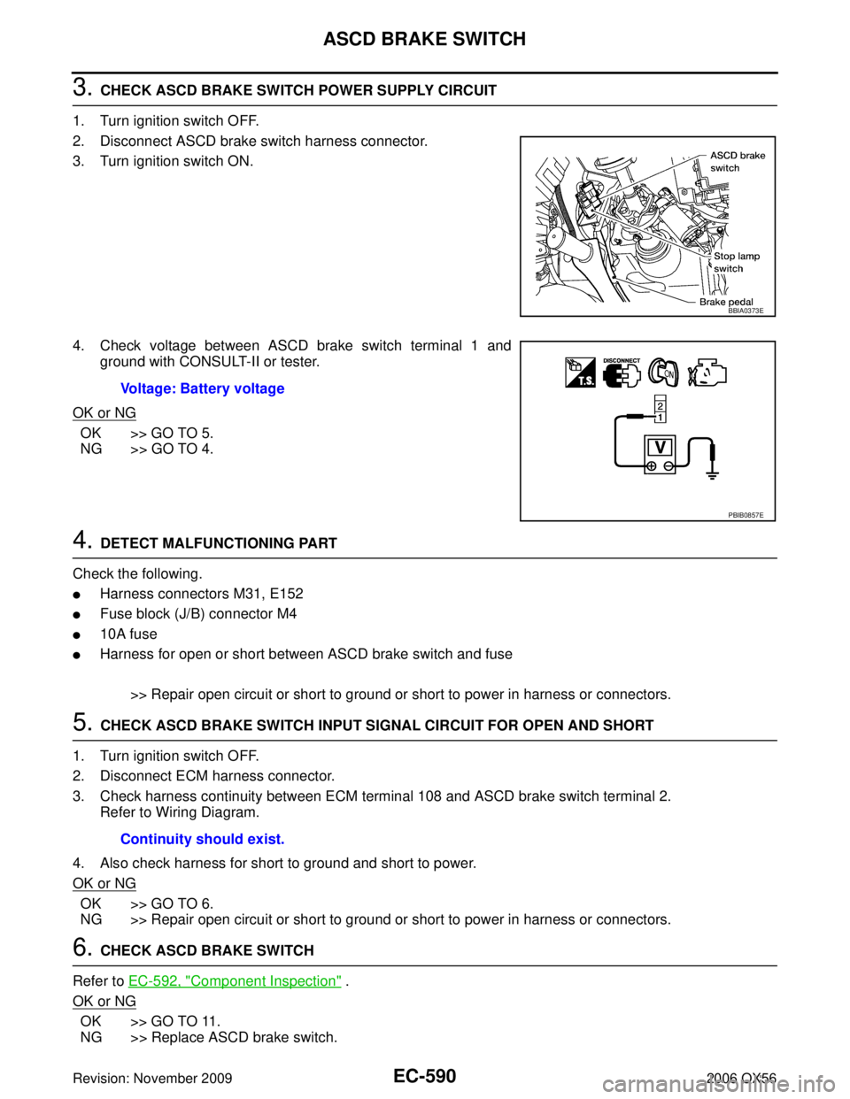
3. CHECK ASCD BRAKE SWITCH POWER SUPPLY CIRCUIT
1. Turn ignition switch OFF.
2. Disconnect ASCD brake switch harness connector.
3. Turn ignition switch ON.
4. Check voltage between ASCD brake switch terminal 1 and ground with CONSULT-II or tester.
OK or NG
OK >> GO TO 5.
NG >> GO TO 4.
4. DETECT MALFUNCTIONING PART
Check the following.
�Harness connectors M31, E152
�Fuse block (J/B) connector M4
�10A fuse
�Harness for open or short between ASCD brake switch and fuse
>> Repair open circuit or short to ground or short to power in harness or connectors.
5. CHECK ASCD BRAKE SWITCH INPUT SIGNAL CIRCUIT FOR OPEN AND SHORT
1. Turn ignition switch OFF.
2. Disconnect ECM harness connector.
3. Check harness continuity between ECM terminal 108 and ASCD brake switch terminal 2. Refer to Wiring Diagram.
4. Also check harness for short to ground and short to power.
OK or NG
OK >> GO TO 6.
NG >> Repair open circuit or short to ground or short to power in harness or connectors.
6. CHECK ASCD BRAKE SWITCH
Refer to EC-592, "
Component Inspection" .
OK or NG
OK >> GO TO 11.
NG >> Replace ASCD brake switch.
BBIA0373E
Voltage: Battery voltage
PBIB0857E
Continuity should exist.
Page 1802 of 3383
ASCD BRAKE SWITCHEC-591
C
DE
F
G H
I
J
K L
M A
EC
Revision: November 2009 2006 QX56
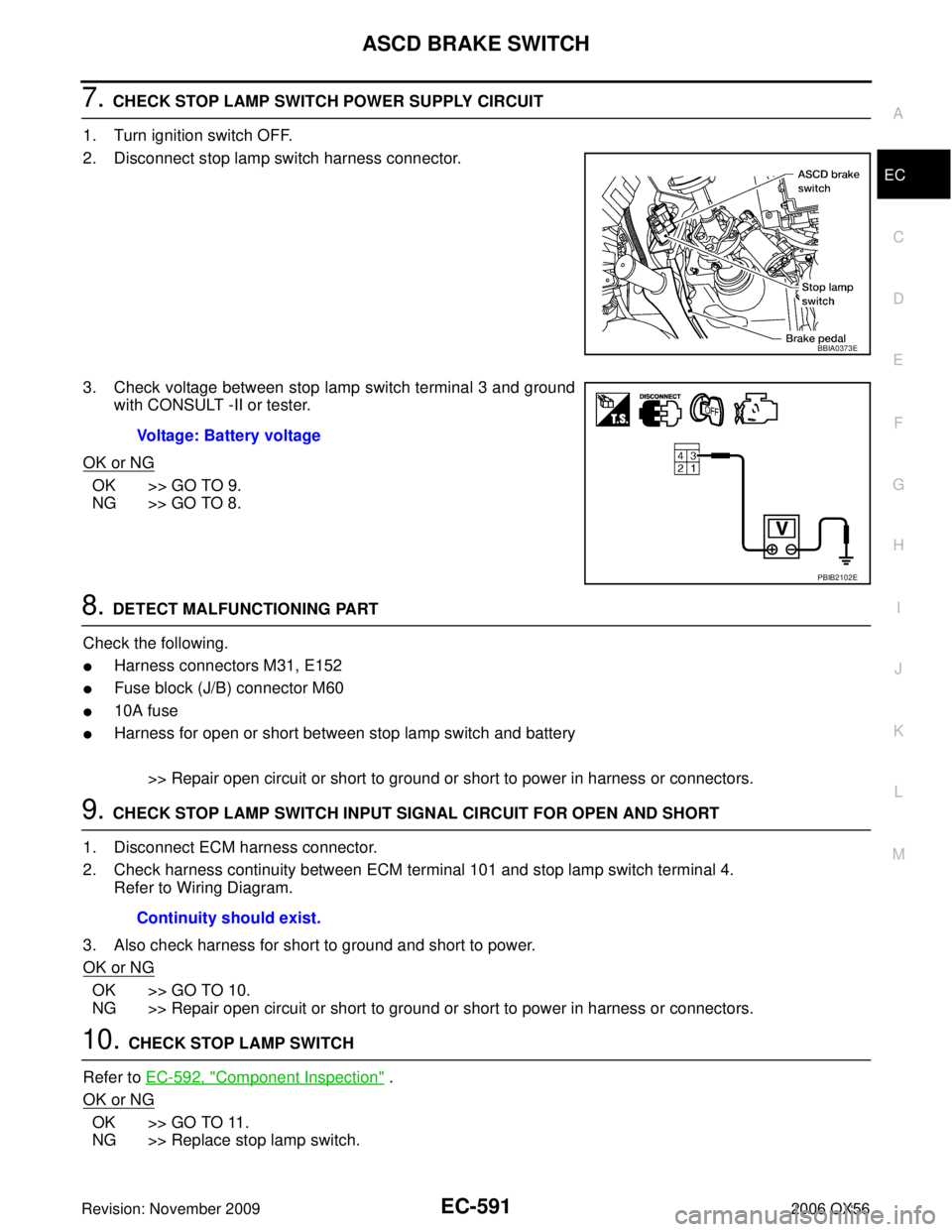
7. CHECK STOP LAMP SWITCH POWER SUPPLY CIRCUIT
1. Turn ignition switch OFF.
2. Disconnect stop lamp switch harness connector.
3. Check voltage between stop lamp switch terminal 3 and ground with CONSULT -II or tester.
OK or NG
OK >> GO TO 9.
NG >> GO TO 8.
8. DETECT MALFUNCTIONING PART
Check the following.
�Harness connectors M31, E152
�Fuse block (J/B) connector M60
�10A fuse
�Harness for open or short between stop lamp switch and battery
>> Repair open circuit or short to ground or short to power in harness or connectors.
9. CHECK STOP LAMP SWITCH INPUT SIGNAL CIRCUIT FOR OPEN AND SHORT
1. Disconnect ECM harness connector.
2. Check harness continuity between ECM terminal 101 and stop lamp switch terminal 4. Refer to Wiring Diagram.
3. Also check harness for short to ground and short to power.
OK or NG
OK >> GO TO 10.
NG >> Repair open circuit or short to ground or short to power in harness or connectors.
10. CHECK STOP LAMP SWITCH
Refer to EC-592, "
Component Inspection" .
OK or NG
OK >> GO TO 11.
NG >> Replace stop lamp switch.
BBIA0373E
Voltage: Battery voltage
PBIB2102E
Continuity should exist.
Page 1813 of 3383
EC-602Revision: November 2009
FUEL INJECTOR
2006 QX56
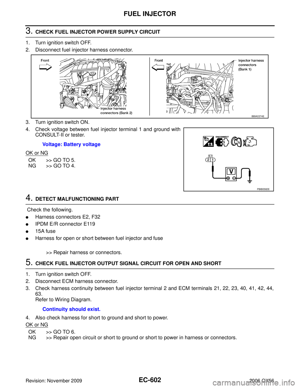
3. CHECK FUEL INJECTOR POWER SUPPLY CIRCUIT
1. Turn ignition switch OFF.
2. Disconnect fuel injector harness connector.
3. Turn ignition switch ON.
4. Check voltage between fuel injector terminal 1 and ground with CONSULT-II or tester.
OK or NG
OK >> GO TO 5.
NG >> GO TO 4.
4. DETECT MALFUNCTIONING PART
Check the following.
�Harness connectors E2, F32
�IPDM E/R connector E119
�15A fuse
�Harness for open or short between fuel injector and fuse
>> Repair harness or connectors.
5. CHECK FUEL INJECTOR OUTPUT SIGNAL CIRCUIT FOR OPEN AND SHORT
1. Turn ignition switch OFF.
2. Disconnect ECM harness connector.
3. Check harness continuity between fuel injector terminal 2 and ECM terminals 21, 22, 23, 40, 41, 42, 44, 63.
Refer to Wiring Diagram.
4. Also check harness for short to ground and short to power.
OK or NG
OK >> GO TO 6.
NG >> Repair open circuit or short to ground or short to power in harness or connectors. Voltage: Battery voltage
BBIA0374E
PBIB0582E
Continuity should exist.
Page 1818 of 3383
FUEL PUMPEC-607
C
DE
F
G H
I
J
K L
M A
EC
Revision: November 2009 2006 QX56
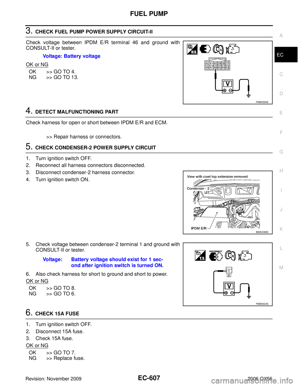
3. CHECK FUEL PUMP POWER SUPPLY CIRCUIT-II
Check voltage between IPDM E/R terminal 46 and ground with
CONSULT-II or tester.
OK or NG
OK >> GO TO 4.
NG >> GO TO 13.
4. DETECT MALFUNCTIONING PART
Check harness for open or short between IPDM E/R and ECM.
>> Repair harness or connectors.
5. CHECK CONDENSER-2 POWER SUPPLY CIRCUIT
1. Turn ignition switch OFF.
2. Reconnect all harness connectors disconnected.
3. Disconnect condenser-2 harness connector.
4. Turn ignition switch ON.
5. Check voltage between condenser-2 terminal 1 and ground with CONSULT-II or tester.
6. Also check harness for short to ground and short to power.
OK or NG
OK >> GO TO 8.
NG >> GO TO 6.
6. CHECK 15A FUSE
1. Turn ignition switch OFF.
2. Disconnect 15A fuse.
3. Check 15A fuse.
OK or NG
OK >> GO TO 7.
NG >> Replace fuse. Voltage: Battery voltage
PBIB2656E
BBIA0388E
Voltage: Battery voltage should exist for 1 sec-
ond after ignition switch is turned ON.
PBIB0624E
Page 1825 of 3383
EC-614Revision: November 2009
ICC BRAKE SWITCH
2006 QX56
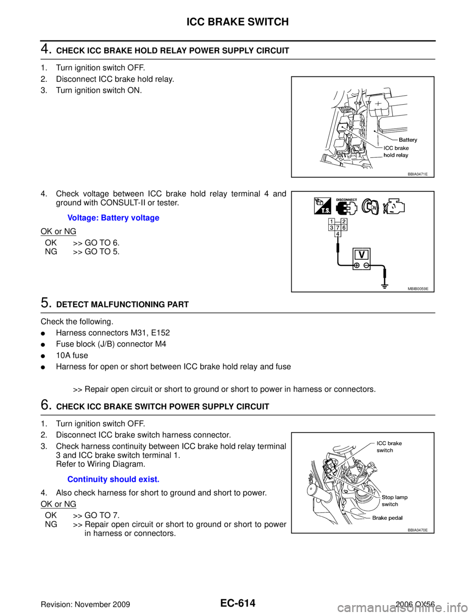
4. CHECK ICC BRAKE HOLD RELAY POWER SUPPLY CIRCUIT
1. Turn ignition switch OFF.
2. Disconnect ICC brake hold relay.
3. Turn ignition switch ON.
4. Check voltage between ICC brake hold relay terminal 4 and ground with CONSULT-II or tester.
OK or NG
OK >> GO TO 6.
NG >> GO TO 5.
5. DETECT MALFUNCTIONING PART
Check the following.
�Harness connectors M31, E152
�Fuse block (J/B) connector M4
�10A fuse
�Harness for open or short between ICC brake hold relay and fuse
>> Repair open circuit or short to ground or short to power in harness or connectors.
6. CHECK ICC BRAKE SWITCH POWER SUPPLY CIRCUIT
1. Turn ignition switch OFF.
2. Disconnect ICC brake switch harness connector.
3. Check harness continuity between ICC brake hold relay terminal 3 and ICC brake switch terminal 1.
Refer to Wiring Diagram.
4. Also check harness for short to ground and short to power.
OK or NG
OK >> GO TO 7.
NG >> Repair open circuit or short to ground or short to power in harness or connectors.
BBIA0471E
Voltage: Battery voltage
MBIB0059E
Continuity should exist.
BBIA0470E
Page 1827 of 3383
EC-616Revision: November 2009
ICC BRAKE SWITCH
2006 QX56
11 . DETECT MALFUNCTIONING PART
Check the following.
�Harness connectors M31, E152
�Fuse block (J/B) No. 1 connector M60
�10A fuse
�Harness for open or short between stop lamp switch and battery
>> Repair open circuit or short to ground or short to power in harness or connectors.
12. CHECK STOP LAMP SWITCH INPUT SIGNAL CIRCUIT FOR OPEN AND SHORT
1. Disconnect ECM harness connector.
2. Check harness continuity between ECM terminal 101 and stop lamp switch terminal 4. Refer to Wiring Diagram.
3. Also check harness for short to ground and short to power.
OK or NG
OK >> GO TO 13.
NG >> Repair open circuit or short to ground or short to power in harness or connectors.
13. CHECK STOP LAMP SWITCH
Refer to EC-617, "
Component Inspection" .
OK or NG
OK >> GO TO 14.
NG >> Replace stop lamp switch.
14. CHECK INTERMITTENT INCIDENT
Refer to EC-144, "
TROUBLE DIAGNOSIS FOR INTERMITTENT INCIDENT" .
>> INSPECTION END
Continuity should exist.
Page 1840 of 3383
IGNITION SIGNALEC-629
C
DE
F
G H
I
J
K L
M A
EC
Revision: November 2009 2006 QX56
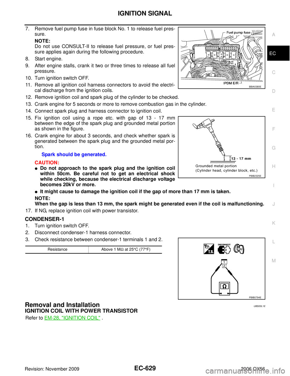
7. Remove fuel pump fuse in fuse block No. 1 to release fuel pres-
sure.
NOTE:
Do not use CONSULT-II to release fuel pressure, or fuel pres-
sure applies again during the following procedure.
8. Start engine.
9. After engine stalls, crank it two or three times to release all fuel pressure.
10. Turn ignition switch OFF.
11. Remove all ignition coil harness connectors to avoid the electri- cal discharge from the ignition coils.
12. Remove ignition coil and spark plug of the cylinder to be checked.
13. Crank engine for 5 seconds or more to remove combustion gas in the cylinder.
14. Connect spark plug and harness connector to ignition coil.
15. Fix ignition coil using a rope etc. with gap of 13 - 17 mm between the edge of the spark plug and grounded metal portion
as shown in the figure.
16. Crank engine for about 3 seconds, and check whether spark is generated between the spark plug and the grounded metal por-
tion.
CAUTION:
�Do not approach to the spark plug and the ignition coil
within 50cm. Be careful not to get an electrical shock
while checking, because the electrical discharge voltage
becomes 20kV or more.
�It might cause to damage the ignition coil if the gap of more than 17 mm is taken.
NOTE:
When the gap is less than 13 mm, the spark might be generated even if the coil is malfunctioning.
17. If NG, replace ignition coil with power transistor.
CONDENSER-1
1. Turn ignition switch OFF.
2. Disconnect condenser-1 harness connector.
3. Check resistance between condenser-1 terminals 1 and 2.
Removal and InstallationUBS00L1E
IGNITION COIL WITH POWER TRANSISTOR
Refer to EM-28, "IGNITION COIL" .
Spark should be generated.
BBIA0380E
PBIB2325E
Resistance
Above 1 MΩ at 25 °C (77 °F)
PBIB0794E
Page 1954 of 3383
CYLINDER HEADEM-63
C
DE
F
G H
I
J
K L
M A
EM
Revision: November 2009 2006 QX56
CYLINDER HEADPFP:11041
On-Vehicle ServiceEBS00RFD
CHECKING COMPRESSION PRESSURE
1. Warm up the engine thoroughly. Then stop the engine.
2. Release the fuel pressure. Refer to EC-80, "
FUEL PRESSURE RELEASE" .
CAUTION:
If CONSULT-II is not used to release fuel pressure leave the fuel pump fuse disconnected until
step 7.
3. Remove the spark plug from each cylinder. Refer to EM-29, "
Removal and Installation" .
4. Connect the engine tachometer (not required in use of CONSULT-II).
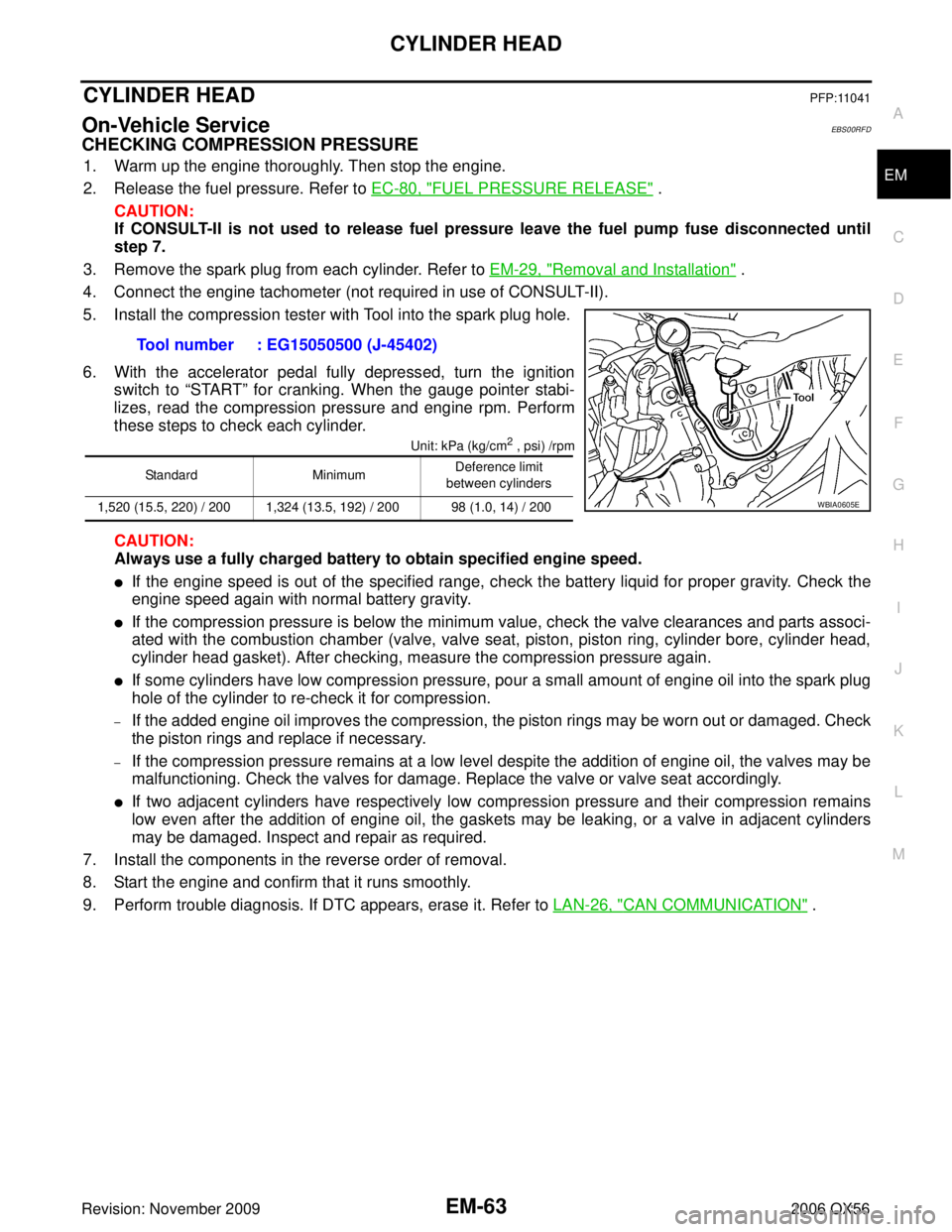
5. Install the compression tester with Tool into the spark plug hole.
6. With the accelerator pedal fully depressed, turn the ignition switch to “START” for cranking. When the gauge pointer stabi-
lizes, read the compression pressure and engine rpm. Perform
these steps to check each cylinder.
Unit: kPa (kg/cm2 , psi) /rpm
CAUTION:
Always use a fully charged battery to obtain specified engine speed.
�If the engine speed is out of the specified range, check the battery liquid for proper gravity. Check the
engine speed again with normal battery gravity.
�If the compression pressure is below the minimum value, check the valve clearances and parts associ-
ated with the combustion chamber (valve, valve seat, piston, piston ring, cylinder bore, cylinder head,
cylinder head gasket). After checking, measure the compression pressure again.
�If some cylinders have low compression pressure, pour a small amount of engine oil into the spark plug
hole of the cylinder to re-check it for compression.
–If the added engine oil improves the compression, the piston rings may be worn out or damaged. Check
the piston rings and replace if necessary.
–If the compression pressure remains at a low level despite the addition of engine oil, the valves may be
malfunctioning. Check the valves for damage. Replace the valve or valve seat accordingly.
�If two adjacent cylinders have respectively low compression pressure and their compression remains
low even after the addition of engine oil, the gaskets may be leaking, or a valve in adjacent cylinders
may be damaged. Inspect and repair as required.
7. Install the components in the reverse order of removal.
8. Start the engine and confirm that it runs smoothly.
9. Perform trouble diagnosis. If DTC appears, erase it. Refer to LAN-26, "
CAN COMMUNICATION" .
Tool number : EG15050500 (J-45402)
Standard
MinimumDeference limit
between cylinders
1,520 (15.5, 220) / 200 1,324 (13.5, 192) / 200 98 (1.0, 14) / 200
WBIA0605E