2006 INFINITI M35 Regulator
[x] Cancel search: RegulatorPage 112 of 5621

A/T CONTROL SYSTEM
AT-33
D
E
F
G
H
I
J
K
L
MA
B
AT
Revision: 2006 January2006 M35/M45
Line Pressure ControlNCS001JS
When an input torque signal equivalent to the engine drive force is sent from the ECM to the TCM, the
TCM controls the line pressure solenoid.
This line pressure solenoid controls the pressure regulator valve as the signal pressure and adjusts the
pressure of the operating oil discharged from the oil pump to the line pressure most appropriate to the
driving state.
LINE PRESSURE CONTROL IS BASED ON THE TCM LINE PRESSURE CHARACTERISTIC
PATTERN
The TCM has stored in memory a number of patterns for the optimum line pressure characteristic for the
driving state.
In order to obtain the most appropriate line pressure characteristic to meet the current driving state, the
TCM controls the line pressure solenoid current value and thus controls the line pressure.
Normal Control
Each clutch is adjusted to the necessary pressure to match the
engine drive force.
Back-up Control (Engine Brake)
When the select operation is performed during driving and the A/T is
shifted down, the line pressure is set according to the vehicle speed.
PCIA0007E
PCIA0008E
PCIA0009E
Page 117 of 5621

AT-38
A/T CONTROL SYSTEM
Revision: 2006 January2006 M35/M45
Engine Brake ControlNCS001JV
The forward one-way clutch transmits the drive force from the engine to the rear wheels. But the reverse
drive from the rear wheels is not transmitted to the engine because the one-way clutch is idling.
Therefore, the low coast brake solenoid is operated to prevent the forward one-way clutch from idling and
the engine brake is operated in the same manner as conventionally.
The operation of the low coast brake solenoid switches the low coast brake switching valve and controls
the coupling and releasing of the low coast brake.
The low coast brake reducing valve controls the low coast brake coupling force.
Control ValveNCS001JW
FUNCTION OF CONTROL VALVE
SCIA1520E
Name Function
Torque converter regulator valveIn order to prevent the pressure supplied to the torque converter from being excessive,
the line pressure is adjusted to the optimum pressure (torque converter operating pres-
sure).
Pressure regulator valve
Pressure regulator plug
Pressure regulator sleeveAdjusts the oil discharged from the oil pump to the optimum pressure (line pressure) for
the driving state.
Front brake control valveWhen the front brake is coupled, adjusts the line pressure to the optimum pressure
(front brake pressure) and supplies it to the front brake. (In 1st, 2nd, 3rd, and 5th gears,
adjusts the clutch pressure.)
Accumulator control valveAdjusts the pressure (accumulator control pressure) acting on the accumulator piston
and low coast reducing valve to the pressure appropriate to the driving state.
Pilot valve AAdjusts the line pressure and produces the constant pressure (pilot pressure) required
for line pressure control, shift change control, and lock-up control.
Pilot valve BAdjusts the line pressure and produces the constant pressure (pilot pressure) required
for shift change control.
Low coast brake switching valve During engine braking, supplies the line pressure to the low coast brake reducing valve.
Low coast brake reducing valveWhen the low coast brake is coupled, adjusts the line pressure to the optimum pressure
(low coast brake pressure) and supplies it to the low coast brake.
N-R accumulator Produces the stabilizing pressure for when N-R is selected.
Direct clutch piston switching valve Operates in 4th gear and switches the direct clutch coupling capacity.
High and low reverse clutch control valveWhen the high and low reverse clutch is coupled, adjusts the line pressure to the opti-
mum pressure (high and low reverse clutch pressure) and supplies it to the high and low
reverse clutch. (In 1st, 3rd, 4th and 5th gears, adjusts the clutch pressure.)
Page 135 of 5621

AT-56
TROUBLE DIAGNOSIS
Revision: 2006 January2006 M35/M45
CAUTION:
Do not reuse O-ring.
Apply ATF to O-ring.
Line Pressure
Judgement of Line Pressure Test
Engine speedLine pressure [kPa (kg/cm
2 , psi)]
“R” position “D”, “M” positions
At idle speed 425 - 465 (4.3 - 4.7, 62 - 67) 379 - 428 (3.9 - 4.4, 55 - 62)
At stall speed 1,605 - 1,950 (16.4 - 19.9, 233 - 283) 1,310 - 1,500 (13.4 - 15.3, 190 - 218)
Judgement Possible cause
Idle speedLow for all positions
(“P”, “R”, “N”, “D”, “M”)Possible causes include malfunctions in the pressure supply system and low oil pump out-
put.
For example
Oil pump wear
Pressure regulator valve or plug sticking or spring fatigue
Oil strainer oil pump pressure regulator valve passage oil leak
Engine idle speed too low
Only low for a specific
positionPossible causes include an oil pressure leak in a passage or device related to the position
after the pressure is distributed by the manual valve.
HighPossible causes include a sensor malfunction or malfunction in the line pressure adjustment
function.
For example
Accelerator pedal position signal malfunction
A/T fluid temperature sensor malfunction
Line pressure solenoid malfunction (sticking in OFF state, filter clog, cut line)
Pressure regulator valve or plug sticking
Stall speedOil pressure does not
rise higher than the oil
pressure for idle.Possible causes include a sensor malfunction or malfunction in the pressure adjustment
function.
For example
Accelerator pedal position signal malfunction
TCM breakdown
Line pressure solenoid malfunction (shorting, sticking in ON state)
Pressure regulator valve or plug sticking
Pilot valve sticking or pilot filter clogged
The pressure rises, but
does not enter the stan-
dard position.Possible causes include malfunctions in the pressure supply system and malfunction in the
pressure adjustment function.
For example
Accelerator pedal position signal malfunction
Line pressure solenoid malfunction (sticking, filter clog)
Pressure regulator valve or plug sticking
Pilot valve sticking or pilot filter clogged
Only low for a specific
positionPossible causes include an oil pressure leak in a passage or device related to the position
after the pressure is distributed by the manual valve.
Page 1135 of 5621
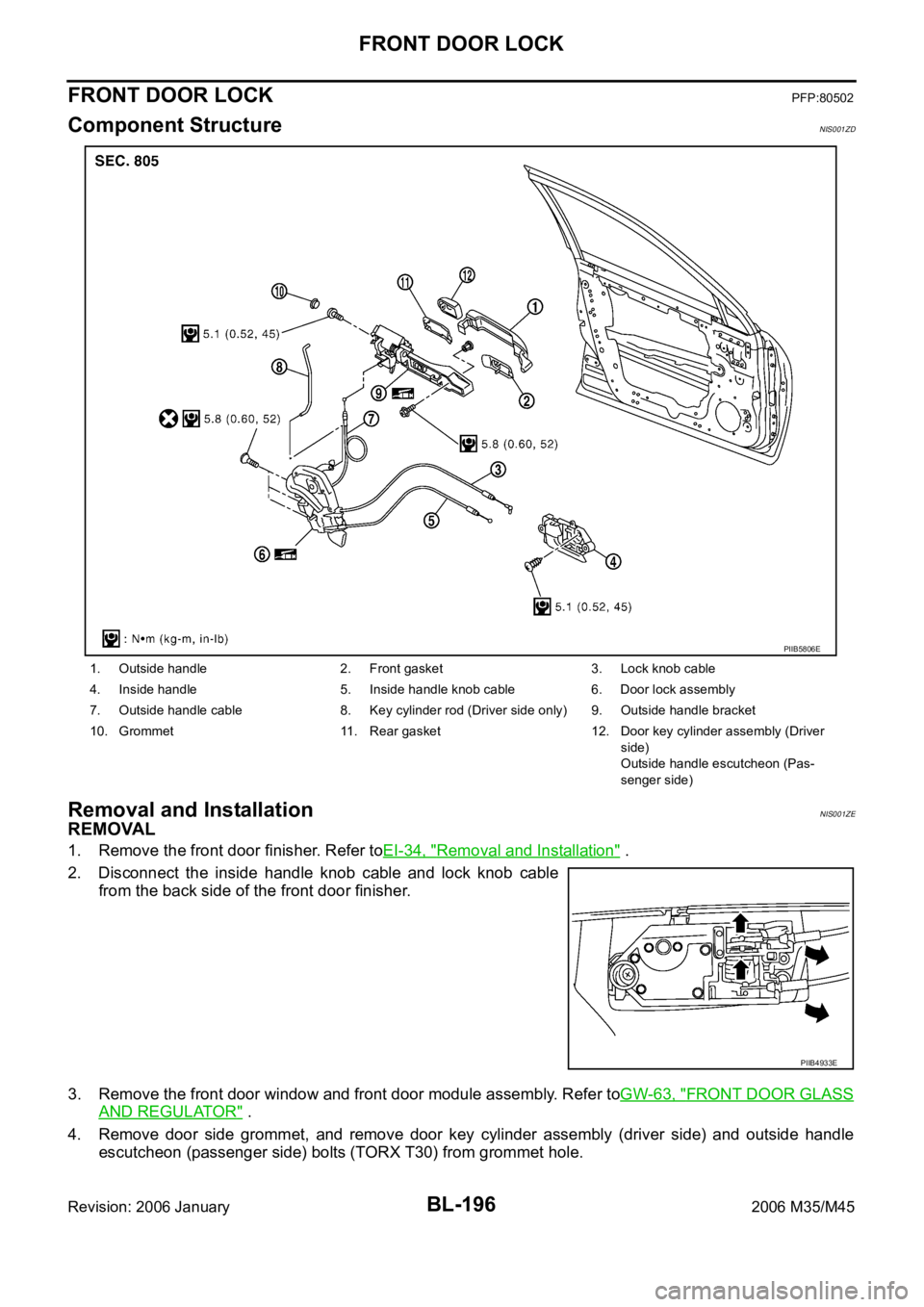
BL-196
FRONT DOOR LOCK
Revision: 2006 January2006 M35/M45
FRONT DOOR LOCKPFP:80502
Component StructureNIS001ZD
Removal and InstallationNIS001ZE
REMOVAL
1. Remove the front door finisher. Refer toEI-34, "Removal and Installation" .
2. Disconnect the inside handle knob cable and lock knob cable
from the back side of the front door finisher.
3. Remove the front door window and front door module assembly. Refer toGW-63, "
FRONT DOOR GLASS
AND REGULATOR" .
4. Remove door side grommet, and remove door key cylinder assembly (driver side) and outside handle
escutcheon (passenger side) bolts (TORX T30) from grommet hole.
1. Outside handle 2. Front gasket 3. Lock knob cable
4. Inside handle 5. Inside handle knob cable 6. Door lock assembly
7. Outside handle cable 8. Key cylinder rod (Driver side only) 9. Outside handle bracket
10. Grommet 11. Rear gasket 12. Door key cylinder assembly (Driver
side)
Outside handle escutcheon (Pas-
senger side)
PIIB5806E
PIIB4933E
Page 1139 of 5621
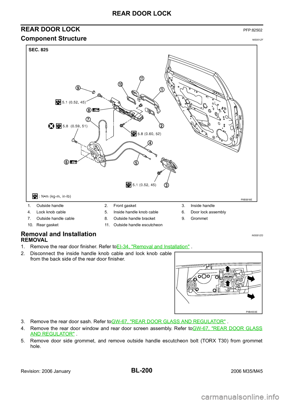
BL-200
REAR DOOR LOCK
Revision: 2006 January2006 M35/M45
REAR DOOR LOCKPFP:82502
Component StructureNIS001ZF
Removal and InstallationNIS001ZG
REMOVAL
1. Remove the rear door finisher. Refer toEI-34, "Removal and Installation" .
2. Disconnect the inside handle knob cable and lock knob cable
from the back side of the rear door finisher.
3. Remove the rear door sash. Refer toGW-67, "
REAR DOOR GLASS AND REGULATOR" .
4. Remove the rear door window and rear door screen assembly. Refer toGW-67, "
REAR DOOR GLASS
AND REGULATOR" .
5. Remove door side grommet, and remove outside handle escutcheon bolt (TORX T30) from grommet
hole.
1. Outside handle 2. Front gasket 3. Inside handle
4. Lock knob cable 5. Inside handle knob cable 6. Door lock assembly
7. Outside handle cable 8. Outside handle bracket 9. Grommet
10. Rear gasket 11. Outside handle escutcheon
PIIB5816E
PIIB4933E
Page 1570 of 5621
![INFINITI M35 2006 Factory Service Manual PRECAUTIONS
EC-27
[VQ35DE]
C
D
E
F
G
H
I
J
K
L
MA
EC
Revision: 2006 January2006 M35/M45
B1 indicates the bank 1, B2 indicates the bank 2 as shown
in the figure.
Do not operate fuel pump when](/manual-img/42/57023/w960_57023-1569.png "INFINITI M35 2006 Factory Service Manual PRECAUTIONS
EC-27
[VQ35DE]
C
D
E
F
G
H
I
J
K
L
MA
EC
Revision: 2006 January2006 M35/M45
B1 indicates the bank 1, B2 indicates the bank 2 as shown
in the figure.
Do not operate fuel pump when")
PRECAUTIONS
EC-27
[VQ35DE]
C
D
E
F
G
H
I
J
K
L
MA
EC
Revision: 2006 January2006 M35/M45
B1 indicates the bank 1, B2 indicates the bank 2 as shown
in the figure.
Do not operate fuel pump when there is no fuel in lines.
–Fuel level sensor unit and fuel pump (1)
–Fuel pressure regulator (2)
–Fuel tank temperature sensor (3)
Tighten fuel hose clamps to the specified torque.
Do not depress accelerator pedal when starting.
Immediately after starting, do not rev up engine unneces-
sarily.
Do not rev up engine just prior to shutdown.
When installing C.B. ham radio or a mobile phone, be sure
to observe the following as it may adversely affect elec-
tronic control systems depending on installation location.
–Keep the antenna as far as possible from the electronic
control units.
–Keep the antenna feeder line more than 20 cm (8 in) away
from the harness of electronic controls.
Do not let them run parallel for a long distance.
–Adjust the antenna and feeder line so that the standing-
wave radio can be kept smaller.
–Be sure to ground the radio to vehicle body.
SEC893C
PBIB2707E
SEF709Y
SEF708Y
Page 1637 of 5621
![INFINITI M35 2006 Factory Service Manual EC-94
[VQ35DE]
BASIC SERVICE PROCEDURE
Revision: 2006 January2006 M35/M45
29. CHECK AIR FUEL RATIO (A/F) SENSOR 1 FUNCTION
With CONSULT-II
1. Turn ignition switch OFF and wait at a least 10 seconds.](/manual-img/42/57023/w960_57023-1636.png "INFINITI M35 2006 Factory Service Manual EC-94
[VQ35DE]
BASIC SERVICE PROCEDURE
Revision: 2006 January2006 M35/M45
29. CHECK AIR FUEL RATIO (A/F) SENSOR 1 FUNCTION
With CONSULT-II
1. Turn ignition switch OFF and wait at a least 10 seconds.")
EC-94
[VQ35DE]
BASIC SERVICE PROCEDURE
Revision: 2006 January2006 M35/M45
29. CHECK AIR FUEL RATIO (A/F) SENSOR 1 FUNCTION
With CONSULT-II
1. Turn ignition switch OFF and wait at a least 10 seconds.
2. Start engine and warm it up to normal operating temperature.
3. Drive the vehicle at a speed of 80 km/h (50 MPH) for a few minutes in D position.
NOTE:
Keep the accelerator pedal as steady as possible during the cruising.
4. Release the accelerator pedal fully until the vehicle speed decreases to 50 km/h (30 MPH).
NOTE:
Never apply brake during releasing the accelerator pedal.
5. Repeat steps 3 to 4 for five times.
6. Stop the vehicle and connect CONSULT-II to the vehicle.
7. Make sure that no (1st trip) DTC is displayed in “SELF-DIAG RESULTS” mode.
OK or NG
OK >> GO TO 4.
NG >> GO TO 31.
30. CHECK AIR FUEL RATIO (A/F) SENSOR 1 FUNCTION
With GST
1. Turn ignition switch OFF and wait at a least 10 seconds.
2. Start engine and warm it up to normal operating temperature.
3. Drive the vehicle at a speed of 80 km/h (50 MPH) for a few minutes in D position.
NOTE:
Keep the accelerator pedal as steady as possible during the cruising.
4. Release the accelerator pedal fully until the vehicle speed decreases to 50 km/h (30 MPH).
NOTE:
Never apply brake during releasing the accelerator pedal.
5. Repeat steps 3 to 4 for five times.
6. Stop the vehicle and connect GST to the vehicle.
7. Make sure that no (1st trip) DTC is displayed.
OK or NG
OK >> GO TO 4.
NG >> GO TO 31.
31. DETECT MALFUNCTIONING PART
Check the following.
Check fuel pressure regulator, and repair or replace if necessary. Refer to EC-98, "FUEL PRESSURE
CHECK" .
Check mass air flow sensor and its circuit, and repair or replace if necessary. Refer to EC-205, "DTC
P0101 MAF SENSOR" and EC-214, "DTC P0102, P0103 MAF SENSOR" .
Check fuel injector and its circuit, and repair or replace if necessary. Refer to EC-679, "FUEL INJECTOR"
.
Check engine coolant temperature sensor and its circuit, and repair or replace if necessary. Refer to EC-
226, "DTC P0117, P0118 ECT SENSOR" and EC-238, "DTC P0125 ECT SENSOR" .
OK or NG
OK >> GO TO 33.
NG >> 1. Repair or replace.
2. GO TO 32.
Page 1642 of 5621
![INFINITI M35 2006 Factory Service Manual BASIC SERVICE PROCEDURE
EC-99
[VQ35DE]
C
D
E
F
G
H
I
J
K
L
MA
EC
Revision: 2006 January2006 M35/M45
2. Install the inline fuel quick disconnected fitting between fuel
damper and injector tube.](/manual-img/42/57023/w960_57023-1641.png "INFINITI M35 2006 Factory Service Manual BASIC SERVICE PROCEDURE
EC-99
[VQ35DE]
C
D
E
F
G
H
I
J
K
L
MA
EC
Revision: 2006 January2006 M35/M45
2. Install the inline fuel quick disconnected fitting between fuel
damper and injector tube.")
BASIC SERVICE PROCEDURE
EC-99
[VQ35DE]
C
D
E
F
G
H
I
J
K
L
MA
EC
Revision: 2006 January2006 M35/M45
2. Install the inline fuel quick disconnected fitting between fuel
damper and injector tube.
3. Connect the fuel pressure test gauge (quick connector adapter
hose) to the inline fuel quick disconnected fitting.
4. Turn ignition switch ON and check for fuel leakage.
5. Start engine and check for fuel leakage.
6. Read the indication of fuel pressure gauge.
7. If result is unsatisfactory, go to next step.
8. Check the following.
Fuel hoses and fuel tubes for clogging
Fuel filter for clogging
Fuel pump
Fuel pressure regulator for clogging
If OK, replace fuel pressure regulator.
If NG, repair or replace.At idling:
Approximately 350 kPa (3.57 kg/cm
2 , 51 psi)
PBIB1571E