2006 INFINITI M35 turn signal
[x] Cancel search: turn signalPage 4846 of 5621
IPDM E/R (INTELLIGENT POWER DISTRIBUTION MODULE ENGINE ROOM)
PG-19
C
D
E
F
G
H
I
J
L
MA
B
PG
Revision: 2006 January2006 M35/M45
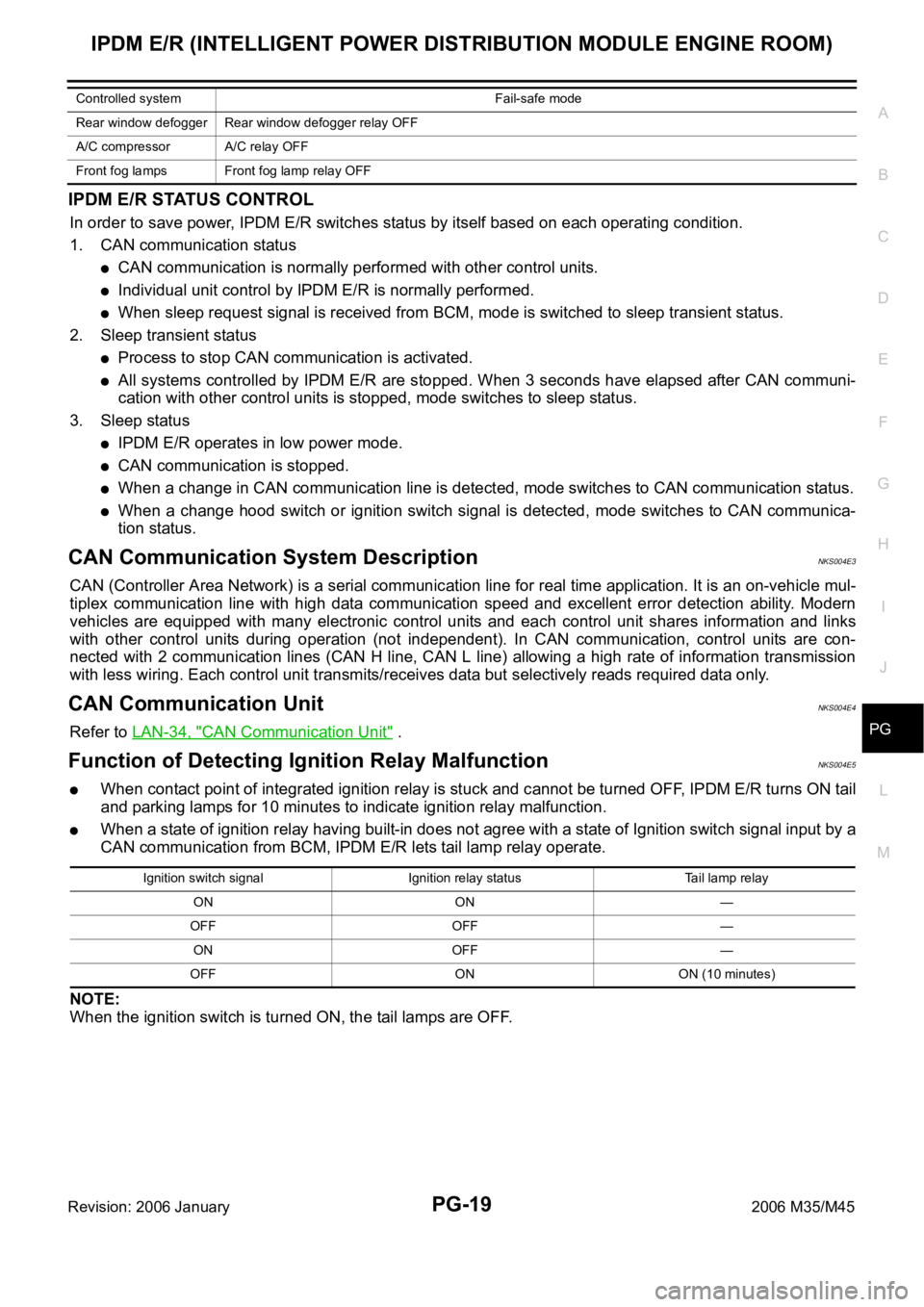
IPDM E/R STATUS CONTROL
In order to save power, IPDM E/R switches status by itself based on each operating condition.
1. CAN communication status
CAN communication is normally performed with other control units.
Individual unit control by IPDM E/R is normally performed.
When sleep request signal is received from BCM, mode is switched to sleep transient status.
2. Sleep transient status
Process to stop CAN communication is activated.
All systems controlled by IPDM E/R are stopped. When 3 seconds have elapsed after CAN communi-
cation with other control units is stopped, mode switches to sleep status.
3. Sleep status
IPDM E/R operates in low power mode.
CAN communication is stopped.
When a change in CAN communication line is detected, mode switches to CAN communication status.
When a change hood switch or ignition switch signal is detected, mode switches to CAN communica-
tion status.
CAN Communication System DescriptionNKS004E3
CAN (Controller Area Network) is a serial communication line for real time application. It is an on-vehicle mul-
tiplex communication line with high data communication speed and excellent error detection ability. Modern
vehicles are equipped with many electronic control units and each control unit shares information and links
with other control units during operation (not independent). In CAN communication, control units are con-
nected with 2 communication lines (CAN H line, CAN L line) allowing a high rate of information transmission
with less wiring. Each control unit transmits/receives data but selectively reads required data only.
CAN Communication UnitNKS004E4
Refer to LAN-34, "CAN Communication Unit" .
Function of Detecting Ignition Relay MalfunctionNKS004E5
When contact point of integrated ignition relay is stuck and cannot be turned OFF, IPDM E/R turns ON tail
and parking lamps for 10 minutes to indicate ignition relay malfunction.
When a state of ignition relay having built-in does not agree with a state of Ignition switch signal input by a
CAN communication from BCM, IPDM E/R lets tail lamp relay operate.
NOTE:
When the ignition switch is turned ON, the tail lamps are OFF.
Rear window defogger Rear window defogger relay OFF
A/C compressor A/C relay OFF
Front fog lamps Front fog lamp relay OFF Controlled system Fail-safe mode
Ignition switch signal Ignition relay status Tail lamp relay
ON ON —
OFF OFF —
ON OFF —
OFF ON ON (10 minutes)
Page 4847 of 5621
PG-20
IPDM E/R (INTELLIGENT POWER DISTRIBUTION MODULE ENGINE ROOM)
Revision: 2006 January2006 M35/M45
CONSULT-II Function (IPDM E/R)NKS004E6
CONSULT-II can display each diagnostic item using the diagnostic test modes shown following.
CONSULT-II BASIC OPERATION
CAUTION:
If CONSULT-II is used with no connection of CONSULT-II CONVERTER, malfunctions might be
detected in self-diagnosis depending on control unit which carry out CAN communication.
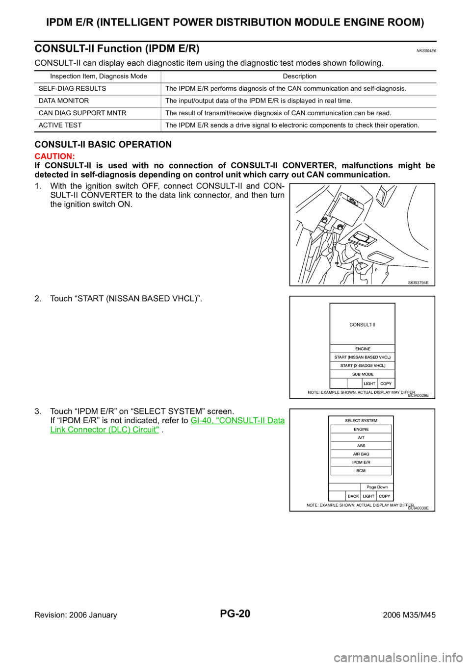
1. With the ignition switch OFF, connect CONSULT-II and CON-
SULT-II CONVERTER to the data link connector, and then turn
the ignition switch ON.
2. Touch “START (NISSAN BASED VHCL)”.
3. Touch “IPDM E/R” on “SELECT SYSTEM” screen.
If “IPDM E/R” is not indicated, refer to GI-40, "
CONSULT-II Data
Link Connector (DLC) Circuit" .
Inspection Item, Diagnosis Mode Description
SELF-DIAG RESULTS The IPDM E/R performs diagnosis of the CAN communication and self-diagnosis.
DATA MONITOR The input/output data of the IPDM E/R is displayed in real time.
CAN DIAG SUPPORT MNTR The result of transmit/receive diagnosis of CAN communication can be read.
ACTIVE TEST The IPDM E/R sends a drive signal to electronic components to check their operation.
SKIB3794E
BCIA0029E
BCIA0030E
Page 4851 of 5621
PG-24
IPDM E/R (INTELLIGENT POWER DISTRIBUTION MODULE ENGINE ROOM)
Revision: 2006 January2006 M35/M45
Auto Active TestNKS004E7
DESCRIPTION
In auto active test mode, operation inspection can be performed when IPDM E/R sends a drive signal to the
following systems:
Rear window defogger
Front wiper (LO, HI)
Tail lamps, parking lamps and license plate lamps
Front fog lamps
Headlamps (LO, HI)
A/C compressor (magnetic clutch)
Cooling fan
Oil pressure warning lamp
OPERATION PROCEDURE
1. Close hood and front door (passenger side), and then lift wiper arms away from windshield (to prevent
glass damage by wiper operation).
NOTE:
When auto active test is performed with hood opened, sprinkle water on windshield beforehand.
2. Turn ignition switch OFF.
3. Turn ignition switch ON, and within 20 seconds, press driver's door switch 10 times (close other doors).
Then turn ignition switch OFF.
4. Turn ignition switch ON within 10 seconds after ignition switch OFF.
5. When auto active test mode is actuated, horn chirps once. Oil pressure warning lamp starts blinking.
6. After a series of operations is repeated three times, auto active test is completed.
NOTE:
When auto active test mode has to be cancelled halfway, turn ignition switch OFF.
CAUTION:
Never start the engine.
If the engine starting operation is made, delete DTC on the self-diag results of CONSULT-II.
Refer to BL-81, "
CONSULT-II Application Items" .
Be sure to inspect GW-52, "Door Switch Check" when the auto active test cannot be performed.
Page 4869 of 5621
PG-42
PDU (POWER DISTRIBUTION UNIT)
Revision: 2006 January2006 M35/M45
Check Push-Button Ignition Switch (Indicator Circuit) SystemNKS004EN
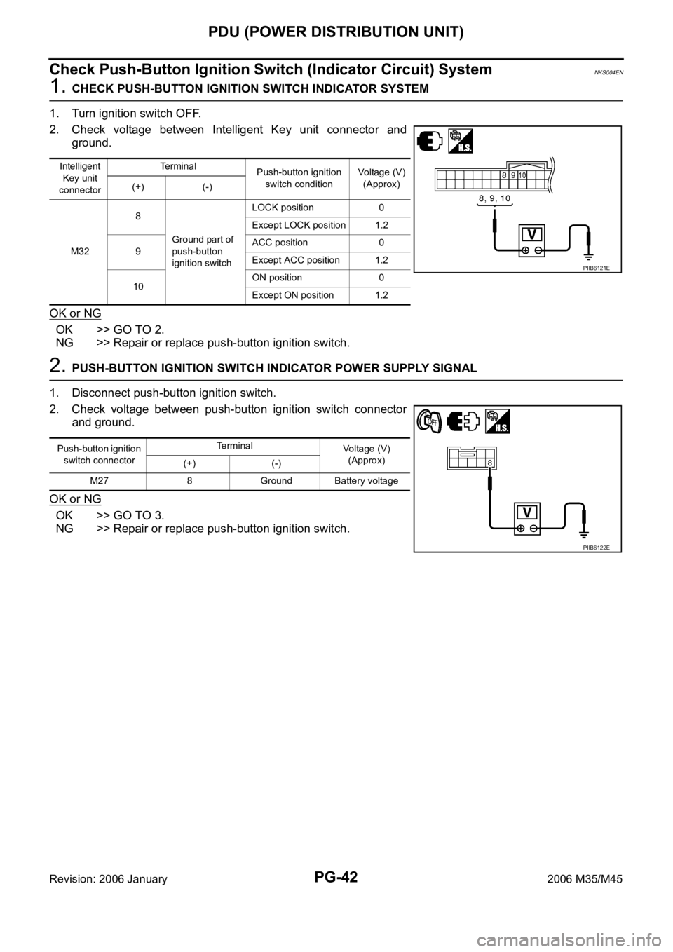
1. CHECK PUSH-BUTTON IGNITION SWITCH INDICATOR SYSTEM
1. Turn ignition switch OFF.
2. Check voltage between Intelligent Key unit connector and
ground.
OK or NG
OK >> GO TO 2.
NG >> Repair or replace push-button ignition switch.
2. PUSH-BUTTON IGNITION SWITCH INDICATOR POWER SUPPLY SIGNAL
1. Disconnect push-button ignition switch.
2. Check voltage between push-button ignition switch connector
and ground.
OK or NG
OK >> GO TO 3.
NG >> Repair or replace push-button ignition switch.
Intelligent
Key unit
connectorTe r m i n a l
Push-button ignition
switch conditionVoltage (V)
(Approx)
(+) (-)
M328
Ground part of
push-button
ignition switchLOCK position 0
Except LOCK position 1.2
9ACC position 0
Except ACC position 1.2
10ON position 0
Except ON position 1.2
PIIB6121E
Push-button ignition
switch connectorTerminal
Voltage (V)
(Approx)
(+) (-)
M27 8 Ground Battery voltage
PIIB6122E
Page 4871 of 5621
PG-44
PDU (POWER DISTRIBUTION UNIT)
Revision: 2006 January2006 M35/M45
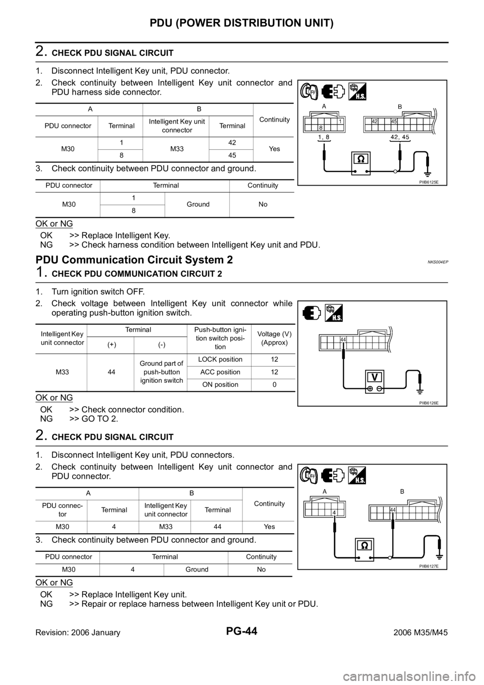
2. CHECK PDU SIGNAL CIRCUIT
1. Disconnect Intelligent Key unit, PDU connector.
2. Check continuity between Intelligent Key unit connector and
PDU harness side connector.
3. Check continuity between PDU connector and ground.
OK or NG
OK >> Replace Intelligent Key.
NG >> Check harness condition between Intelligent Key unit and PDU.
PDU Communication Circuit System 2NKS004EP
1. CHECK PDU COMMUNICATION CIRCUIT 2
1. Turn ignition switch OFF.
2. Check voltage between Intelligent Key unit connector while
operating push-button ignition switch.
OK or NG
OK >> Check connector condition.
NG >> GO TO 2.
2. CHECK PDU SIGNAL CIRCUIT
1. Disconnect Intelligent Key unit, PDU connectors.
2. Check continuity between Intelligent Key unit connector and
PDU connector.
3. Check continuity between PDU connector and ground.
OK or NG
OK >> Replace Intelligent Key unit.
NG >> Repair or replace harness between Intelligent Key unit or PDU.
AB
Continuity
PDU connector TerminalIntelligent Key unit
connectorTerminal
M301
M3342
Ye s
845
PDU connector Terminal Continuity
M301
Ground No
8
PIIB6125E
Intelligent Key
unit connectorTerminal Push-button igni-
tion switch posi-
tionVoltage (V)
(Approx)
(+) (-)
M33 44Ground part of
push-button
ignition switchLOCK position 12
ACC position 12
ON position 0
PIIB6126E
AB
Continuity
PDU connec-
torTerminalIntelligent Key
unit connectorTerminal
M30 4 M33 44 Yes
PDU connector Terminal Continuity
M30 4 Ground No
PIIB6127E
Page 4922 of 5621

HARNESS
PG-95
C
D
E
F
G
H
I
J
L
MA
B
PG
Revision: 2006 January2006 M35/M45
PGC/V EC EVAP Canister Purge Volume Control Solenoid Valve
PHASE EC Camshaft Position Sensor (PHASE)
PHSB1 EC Camshaft Position Sensor (PHASE) (Bank 1)
PHSB2 EC Camshaft Position Sensor (PHASE) (Bank 2)
PNP/SW AT Park/Neutral Position Switch
PNP/SW EC Park/Neutral Position Switch
POS EC Crankshaft Position Sensor (CKPS) (POS)
POWER PG Power Supply Routing Circuit
PRE/SE EC EVAP Control System Pressure Sensor
PS/SEN EC Power Steering Pressure Sensor
PSB SB Pre-Crash Seat Belt
R/SEAT SE Auto Return Seat
RAS STC Rear Active Steer
ROOM/L LT Interior Room Lamp
RP/SEN EC Refrigerant Pressure Sensor
SEAT SE Power Seat
SEN/PW EC Sensor Power Supply
SHADE EI Rear Sunshade
SHIFT AT A/T Shift Lock System
SNOWSW EC Snow Mode Switch
SROOF RF Sunroof
SRS SRS Supplemental Restraint System
START SC Starting System
STOP/L LT Stop Lamp
STSIG AT Start Signal Circuit
T/WARN WT Low Tire Pressure Warning System
TAIL/L LT Parking, License and Tail Lamps
TLID BL Trunk Lid Opener
TPS1 EC Throttle Position Sensor (Sensor 1)
TPS2 EC Throttle Position Sensor (Sensor 2)
TPS3 EC Throttle Position Sensor
TRNSCV BL Homelink Universal Transceiver
TURN LT Turn Signal and Hazard Warning Lamp
VDC BRC Vehicle Dynamics Control System
VEHSEC BL Vehicle Security System
VENT/V EC EVAP Canister Vent Control Valve
VIAS EC Variable Induction Air Control System
VIAS/V EC VIAS Control Solenoid Valve
VSSA/T AT Vehicle speed Sensor A/T (Revolution Sensor)
WARN DI Warning Lamps
WINDOW GW Power Window
WIPER WW Front Wiper and Washer Code Section Wiring Diagram Name
Page 5024 of 5621

SUNROOF
RF-11
C
D
E
F
G
H
J
K
L
MA
B
RF
Revision: 2006 January2006 M35/M45
System DescriptionNIS0023R
Power supplied at all time
through 50A fusible link (letter F , located in the fuse and fusible link box)
to BCM terminal 55.
through 10A fuse [No.21, located in the fuse block (J/B)]
to BCM terminal 42.
through BCM terminal 54
to sunroof motor assembly terminal 1.
When ignition switch ON or START position,
Power is supplied
through 15A fuse [No.1, located in the fuse block (J/B)]
to BCM terminal 38.
through BCM terminal 53
to sunroof motor assembly terminal 6.
Ground is supplied
to BCM terminal 52
through body grounds M16 and M70.
to sunroof motor assembly terminal 8
through body ground M16 and M70.
TILT UP / SLIDE CLOSE OPERATION
When tilt up / slide close switch is pressed,
Ground is supplied
to sunroof motor assembly terminal 11
through sunroof switch terminal 3
through sunroof switch terminal 2
through sunroof motor assembly terminal 9.
Then, the sunroof tilt up / slide close.
TILT DOWN / SLIDE OPEN OPERATION
When tilt down / slide open switch is pressed,
Ground is supplied
to sunroof motor assembly terminal 4
through sunroof switch terminal 1
through sunroof switch terminal 2
through sunroof motor assembly terminal 9.
Then, the sunroof tilt down / slide open.
AUTO OPERATION
The power sunroof AUTO feature makes it possible to slide open and slide close or tilt up and tilt down the
sunroof without holding the sunroof switch in the SLIDE OPEN/TILT DOWN or SLIDE CLOSE/TILT UP posi-
tion.
RETAINED POWER OPERATION
When the ignition switch is turned to OFF position from ON position, power is supplied for 45 seconds.
through BCM terminal 53.
to sunroof motor assembly terminal 6.
When power is supplied, the sunroof can be operated.
The retained power operation is canceled when the driver or passenger side door is opened.
RAP signal period can be changed by CONSULT-II. Refer to RF-16, "
CONSULT-II Function (BCM)" .
Page 5025 of 5621

RF-12
SUNROOF
Revision: 2006 January2006 M35/M45
ANTI-PINCH FUNCTION
The CPU of sunroof motor assembly monitors the sunroof motor operation and the sunroof position (fully-
closed or other) by the signals from sunroof motor.
When sunroof motor detects an interruption during the following slide close and tilt down operation, sunroof
motor assembly controls the motor until full up position (when tilt down operate) or 125 mm (4.92 in) or more to
open direction (when slide close operate).
The function is operated in the following conditions.
close operation and tilt down when ignition switch is in the ON position.
close operation and tilt down during retained power operation.
INITIALIZATION PROCEDURE
If the battery is disconnected, the sunroof motor connector is disconnected sunroof does not close or open
automatically, use the following procedure to return sunroof operation to normal.
1. Close the sunroof if it is not in the closed position. It may be necessary to repeatedly push the switch to
close the sunroof.
2. Press the SLIDE OPEH/TILT DOWN switch for approximately 1 second or more.
3. Initialization procedure is completed. Confirm proper operation of the sunroof (slide open, slide close, tilt
up, tilt down.)