2006 INFINITI M35 diagram
[x] Cancel search: diagramPage 1327 of 5621
![INFINITI M35 2006 Factory Service Manual BRC-16
[VDC/TCS/ABS]
TROUBLE DIAGNOSIS
Revision: 2006 January2006 M35/M45
Wiring Diagram — VDC — NFS000QE
TFWT0261E INFINITI M35 2006 Factory Service Manual BRC-16
[VDC/TCS/ABS]
TROUBLE DIAGNOSIS
Revision: 2006 January2006 M35/M45
Wiring Diagram — VDC — NFS000QE
TFWT0261E](/manual-img/42/57023/w960_57023-1326.png)
BRC-16
[VDC/TCS/ABS]
TROUBLE DIAGNOSIS
Revision: 2006 January2006 M35/M45
Wiring Diagram — VDC — NFS000QE
TFWT0261E
Page 1434 of 5621
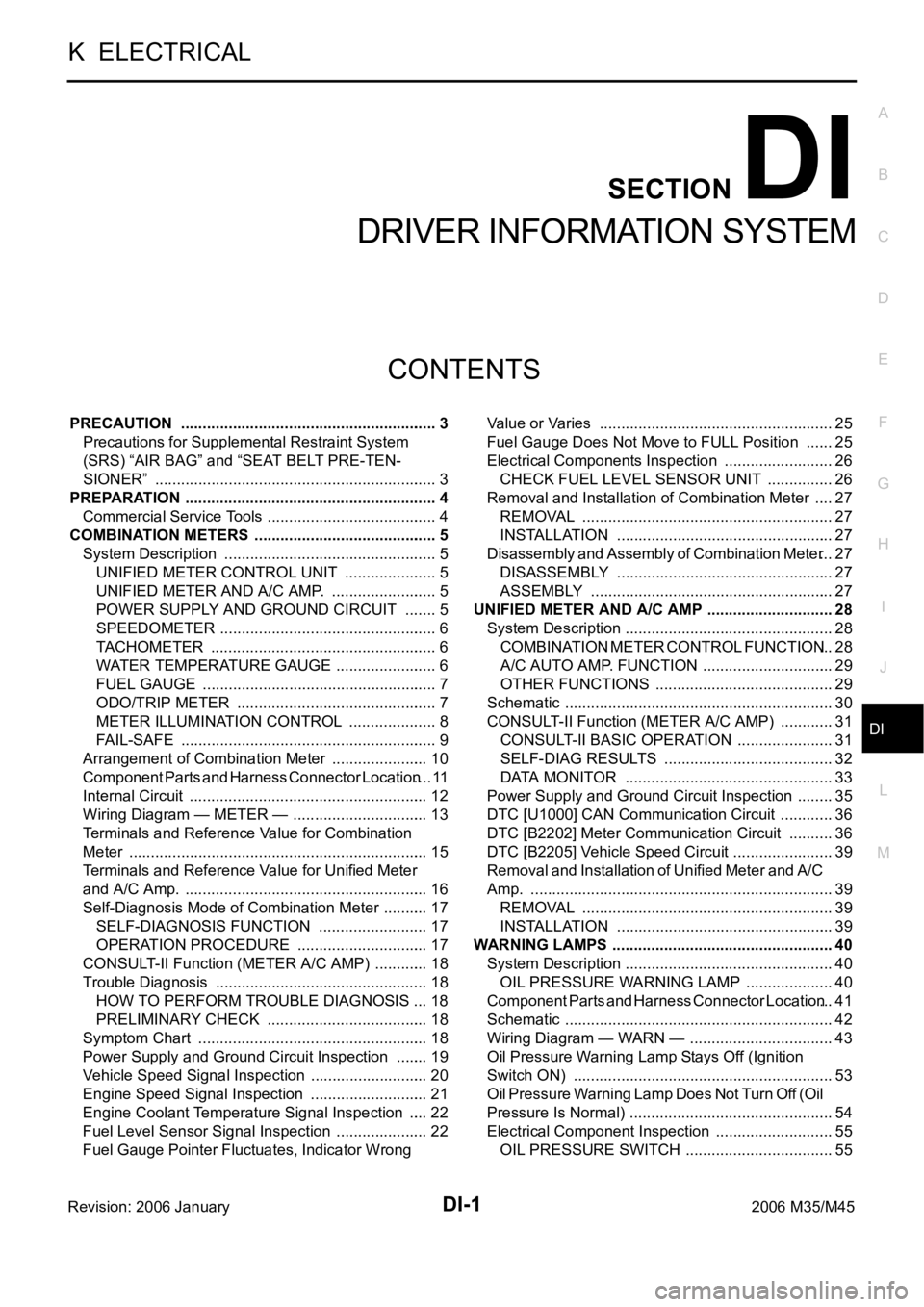
DI-1
DRIVER INFORMATION SYSTEM
K ELECTRICAL
CONTENTS
C
D
E
F
G
H
I
J
L
M
SECTION DI
A
B
DI
Revision: 2006 January2006 M35/M45
DRIVER INFORMATION SYSTEM
PRECAUTION ............................................................ 3
Precautions for Supplemental Restraint System
(SRS) “AIR BAG” and “SEAT BELT PRE-TEN-
SIONER” .................................................................. 3
PREPARATION ........................................................... 4
Commercial Service Tools ........................................ 4
COMBINATION METERS ........................................... 5
System Description .................................................. 5
UNIFIED METER CONTROL UNIT ...................... 5
UNIFIED METER AND A/C AMP. ......................... 5
POWER SUPPLY AND GROUND CIRCUIT ........ 5
SPEEDOMETER ................................................... 6
TACHOMETER ..................................................... 6
WATER TEMPERATURE GAUGE ........................ 6
FUEL GAUGE ....................................................... 7
ODO/TRIP METER ............................................... 7
METER ILLUMINATION CONTROL ..................... 8
FAIL-SAFE ............................................................ 9
Arrangement of Combination Meter ....................... 10
Component Parts and Harness Connector Location .... 11
Internal Circuit ........................................................ 12
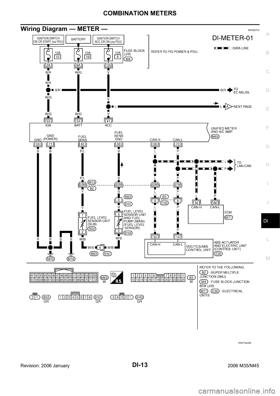
Wiring Diagram — METER — ................................ 13
Terminals and Reference Value for Combination
Meter ...................................................................... 15
Terminals and Reference Value for Unified Meter
and A/C Amp. ......................................................... 16
Self-Diagnosis Mode of Combination Meter ........... 17
SELF-DIAGNOSIS FUNCTION .......................... 17
OPERATION PROCEDURE ............................... 17
CONSULT-II Function (METER A/C AMP) ............. 18
Trouble Diagnosis .................................................. 18
HOW TO PERFORM TROUBLE DIAGNOSIS ... 18
PRELIMINARY CHECK ...................................... 18
Symptom Chart ...................................................... 18
Power Supply and Ground Circuit Inspection ........ 19
Vehicle Speed Signal Inspection ............................ 20
Engine Speed Signal Inspection ............................ 21
Engine Coolant Temperature Signal Inspection ..... 22
Fuel Level Sensor Signal Inspection ...................... 22
Fuel Gauge Pointer Fluctuates, Indicator Wrong Value or Varies ....................................................... 25
Fuel Gauge Does Not Move to FULL Position ....... 25
Electrical Components Inspection .......................... 26
CHECK FUEL LEVEL SENSOR UNIT ................ 26
Removal and Installation of Combination Meter ..... 27
REMOVAL ........................................................
... 27
INSTALLATION ................................................... 27
Disassembly and Assembly of Combination Meter ... 27
DISASSEMBLY ................................................... 27
ASSEMBLY ......................................................... 27
UNIFIED METER AND A/C AMP ...........................
... 28
System Description ................................................. 28
COMBINATION METER CONTROL FUNCTION ... 28
A/C AUTO AMP. FUNCTION ............................... 29
OTHER FUNCTIONS .......................................... 29
Schematic ............................................................... 30
CONSULT-II Function (METER A/C AMP) ............. 31
CONSULT-II BASIC OPERATION ....................... 31
SELF-DIAG RESULTS ........................................ 32
DATA MONITOR ................................................. 33
Power Supply and Ground Circuit Inspection ......... 35
DTC [U1000] CAN Communication Circuit ............. 36
DTC [B2202] Meter Communication Circuit ........... 36
DTC [B2205] Vehicle Speed Circuit ........................ 39
Removal and Installation of Unified Meter and A/C
Amp. ....................................................................... 39
REMOVAL ........................................................
... 39
INSTALLATION ................................................... 39
WARNING LAMPS .................................................... 40
System Description ................................................. 40
OIL PRESSURE WARNING LAMP ..................... 40
Component Parts and Harness Connector Location ... 41
Schematic ............................................................... 42
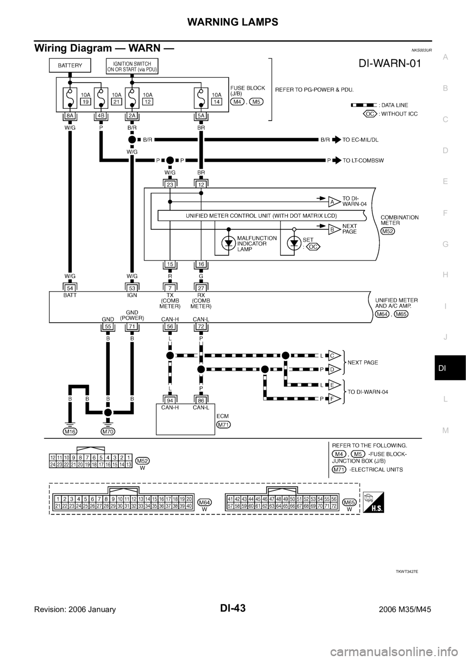
Wiring Diagram — WARN — .................................. 43
Oil Pressure Warning Lamp Stays Off (Ignition
Switch ON) ............................................................. 53
Oil Pressure Warning Lamp Does Not Turn Off (Oil
Pressure Is Normal) ................................................ 54
Electrical Component Inspection ............................ 55
OIL PRESSURE SWITCH ................................... 55
Page 1435 of 5621

DI-2Revision: 2006 January2006 M35/M45 A/T INDICATOR ........................................................ 56
System Description ................................................. 56
MANUAL MODE .................................................. 56
NOT MANUAL MODE ......................................... 56
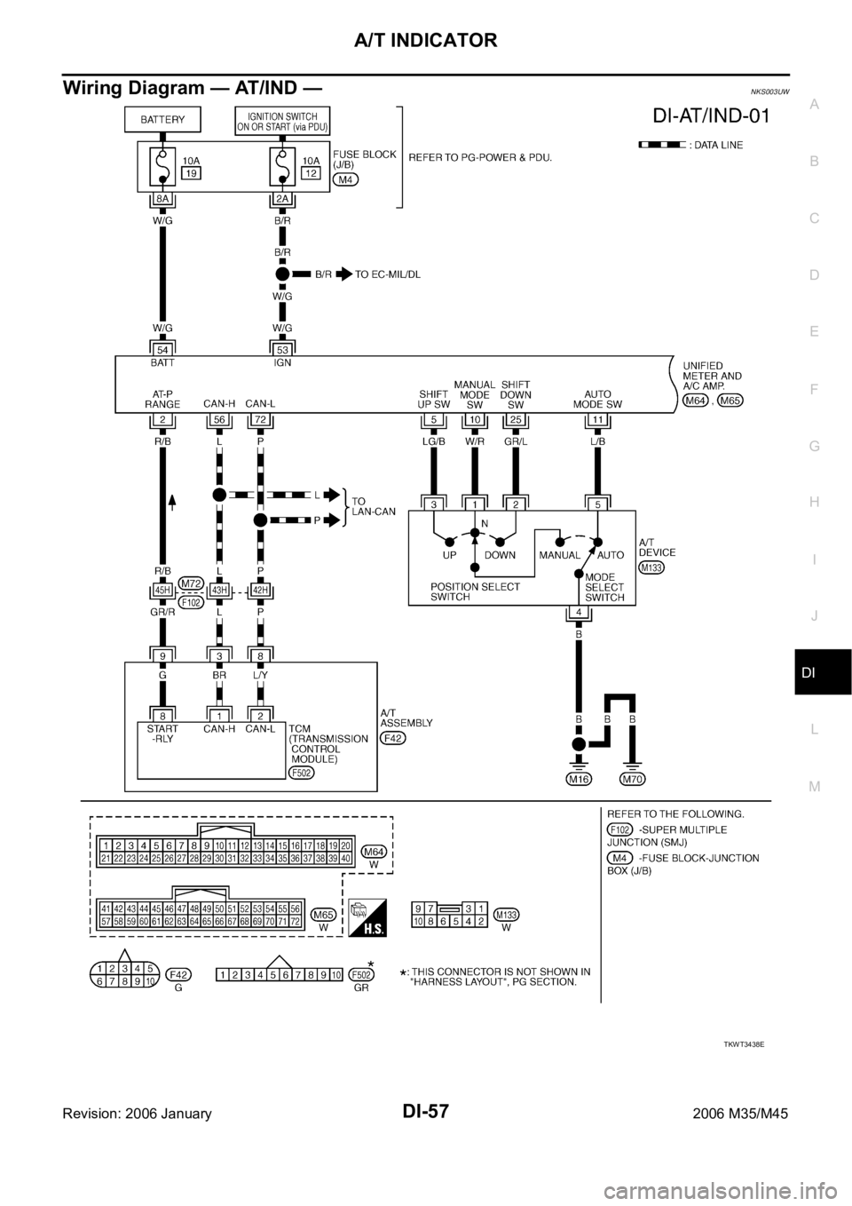
Wiring Diagram — AT/IND — ................................. 57
A/T Indicator Is Malfunction .................................... 59
WARNING CHIME .................................................. ... 60
System Description ................................................. 60
POWER SUPPLY AND GROUND CIRCUIT ....... 60
IGNITION KEY WARNING CHIME (WITH INTEL-
LIGENT KEY) ...................................................... 61
LIGHT WARNING CHIME ................................... 61
SEAT BELT WARNING CHIME ........................... 61
Component Parts and Harness Connector Location ... 62
Schematic ............................................................... 63
Wiring Diagram — CHIME — ................................. 64
Terminals and Reference Value for Combination
Meter ...................................................................... 67
Terminals and Reference Value for Unified Meter
and A/C Amp. ......................................................... 67
Terminals and Reference Value for BCM ................ 68
CONSULT-II Function (BCM) .................................. 69
CONSULT-II BASIC OPERATION ....................... 69
DATA MONITOR .................................................. 70
ACTIVE TEST ..................................................... 71
SELF-DIAG RESULTS ........................................ 71
CONSULT-II Function (METER A/C AMP) ............. 71
Trouble Diagnosis ................................................... 71
HOW TO PERFORM TROUBLE DIAGNOSIS .... 71
PRELIMINARY INSPECTION ............................. 71
SYMPTOM CHART ............................................. 72
Meter Buzzer Circuit Inspection .............................. 72
Lighting Switch Signal Inspection ........................... 73
Front Door Switch (Driver Side) Signal Inspection ... 73
Seat Belt Buckle Switch Signal Inspection ............. 74
Electrical Component Inspection ............................ 76
FRONT DOOR SWITCH (DRIVER SIDE) ........... 76
SEAT BELT BUCKLE SWITCH (DRIVER SIDE) ... 76
CAN COMMUNICATION ........................................... 77
System Description ................................................. 77
CAN Communication Unit ....................................... 77
LANE DEPARTURE WARNING SYSTEM ................ 78
Precautions for Lane Departure Warning (LDW)
system .................................................................... 78
System Description ................................................. 78
LDW SYSTEM OPERATION ............................... 78
POWER SUPPLY AND GROUND CIRCUIT ....... 80
Action Test ...........................................................
... 80
LDW SYSTEM RUNNING TEST ......................... 80
Camera Aiming Adjustment .................................... 81
OUTLINE ............................................................. 81
PREPARATION ................................................... 81TARGET SETTING .............................................. 81
VEHICLE HEIGHT CHECK ................................. 84
AIMING ADJUSTMENT ....................................... 84
Component Parts and Harness Connector Location ... 88
Wiring Diagram — LDW — ..................................... 89
Terminals and Reference Value for LDW Camera
Unit .......................................................................... 91
CONSULT-II Function (LDW) .................................. 91
DESCRIPTION .................................................... 91
CONSULT-II BASIC OPERATION ....................... 91
WORK SUPPORT ............................................... 92
SELF-DIAG RESULTS ......................................... 92
DATA MONITOR .................................................. 93
ACTIVE TEST ...................................................... 94
Trouble Diagnosis ................................................... 95
HOW TO PERFORM TROUBLE DIAGNOSIS .... 95
PRELIMINARY INSPECTION .............................. 95
SYMPTOM CHART .............................................. 96
Power Supply and Ground Circuit Inspection ......... 96
DTC [C1B00] CAMERA UNIT MALF ...................... 97
DTC [C1B01] CAM AIMING INCMP ....................... 97
DTC [C1B02] VHCL SPD DATA MALF ................... 97
DTC [C1B03] ABNRML TEMP DETECT ................ 97
DTC [U1000] CAN COMM CIRCUIT ...................... 98
DTC [U1010] CONTROL UNIT (CAN) .................... 98
LDW Chime Circuit Inspection ................................ 98
LDW Switch Circuit Inspection ................................ 99
LDW Indicator Lamp Circuit Inspection .................102
Turn Signal Input Inspection .................................103
Electrical Component Inspection ..........................103
LDW SWITCH ....................................................103
Removal and Installation for LDW Camera Unit ...103
REMOVAL ..........................................................103
INSTALLATION ..................................................103
Removal and Installation for LDW Chime .............104
REMOVAL ..........................................................104
INSTALLATION ..................................................104
Removal and Installation for LDW Switch .............104
COMPASS ...............................................................105
System Description ...............................................105
DIRECTION DISPLAY .......................................105
Zone Variation Change Procedure ........................105
Correction Functions of the Compass Display ......105
AUTOMATIC CORRECTION .............................105
MANUAL CORRECTION PROCEDURE ...........105
Wiring Diagram – COMPAS – ...............................106
Removal and Installation of Compass ...................107
CLOCK ....................................................................108
Wiring Diagram — CLOCK — ...............................108
Removal and Installation of Clock .........................109
REMOVAL ..........................................................109
INSTALLATION ..................................................109
Page 1446 of 5621
COMBINATION METERS
DI-13
C
D
E
F
G
H
I
J
L
MA
B
DI
Revision: 2006 January2006 M35/M45
Wiring Diagram — METER —NKS003TZ
TKWT3422E
Page 1476 of 5621
WARNING LAMPS
DI-43
C
D
E
F
G
H
I
J
L
MA
B
DI
Revision: 2006 January2006 M35/M45
Wiring Diagram — WARN —NKS003UR
TKWT3427E
Page 1490 of 5621
A/T INDICATOR
DI-57
C
D
E
F
G
H
I
J
L
MA
B
DI
Revision: 2006 January2006 M35/M45
Wiring Diagram — AT/IND —NKS003UW
TKWT3438E
Page 1497 of 5621
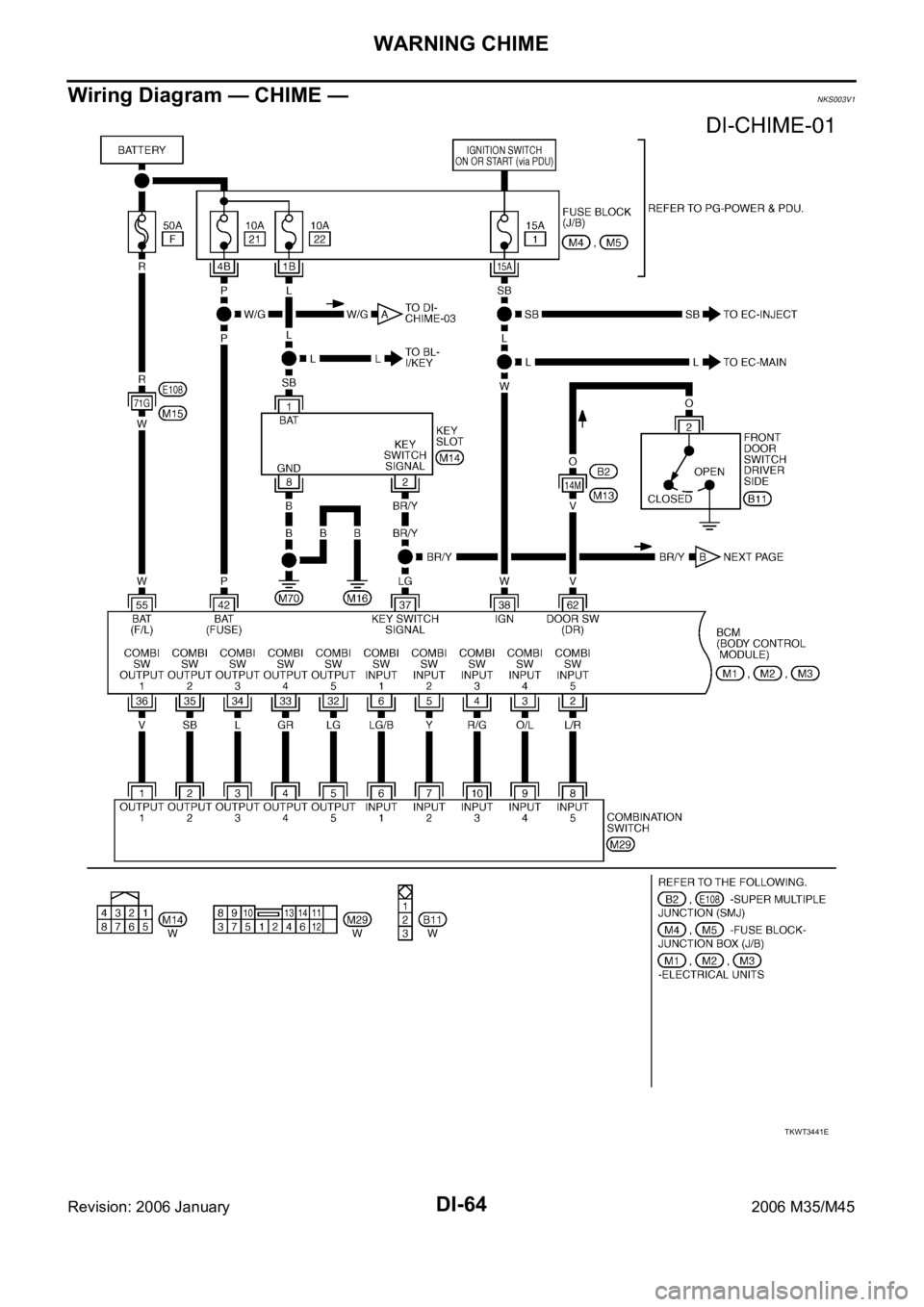
DI-64
WARNING CHIME
Revision: 2006 January2006 M35/M45
Wiring Diagram — CHIME —NKS003V1
TKWT3441E
Page 1513 of 5621
DI-80
LANE DEPARTURE WARNING SYSTEM
Revision: 2006 January2006 M35/M45
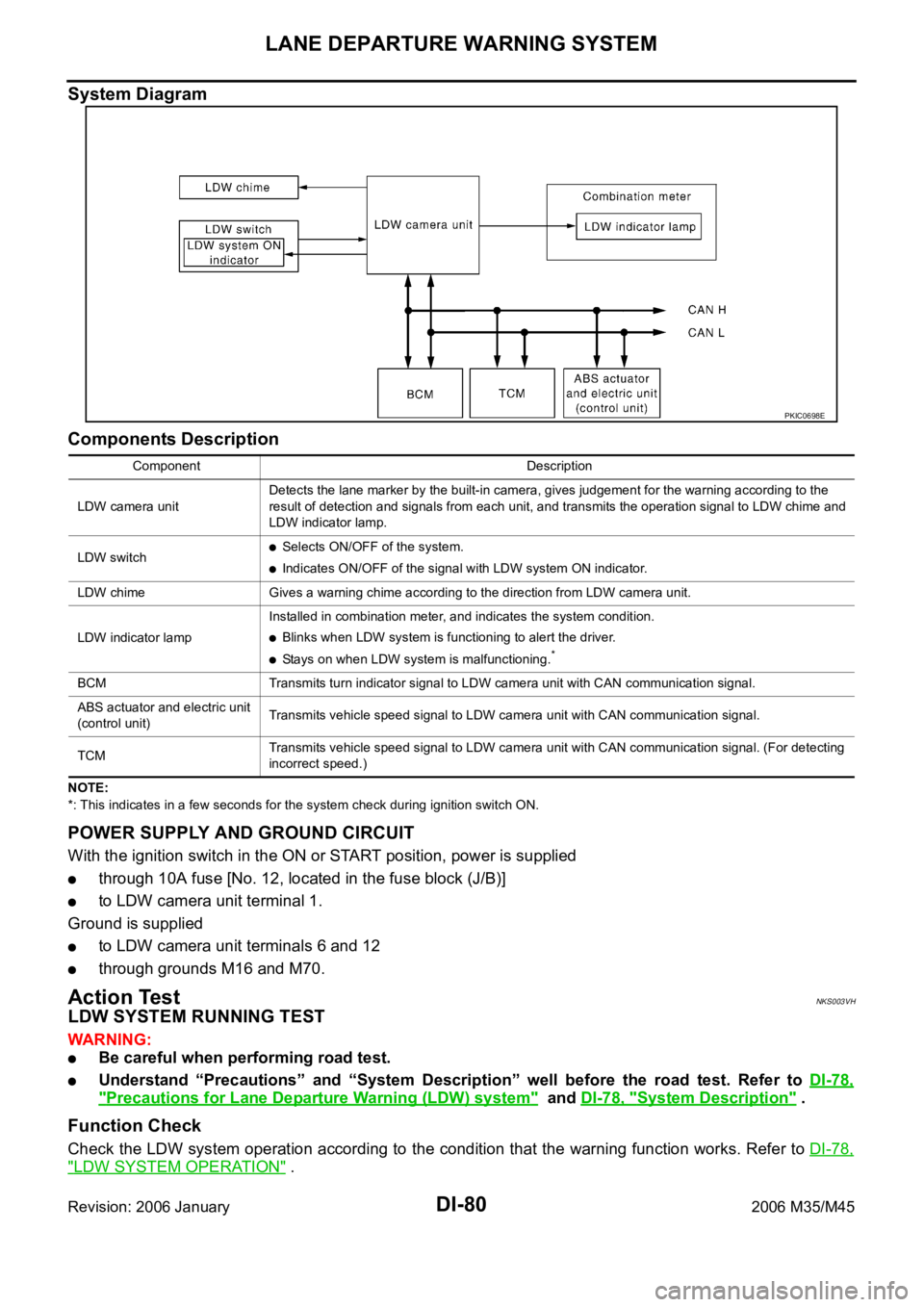
System Diagram
Components Description
NOTE:
*: This indicates in a few seconds for the system check during ignition switch ON.
POWER SUPPLY AND GROUND CIRCUIT
With the ignition switch in the ON or START position, power is supplied
through 10A fuse [No. 12, located in the fuse block (J/B)]
to LDW camera unit terminal 1.
Ground is supplied
to LDW camera unit terminals 6 and 12
through grounds M16 and M70.
Action TestNKS003VH
LDW SYSTEM RUNNING TEST
WAR NING :
Be careful when performing road test.
Understand “Precautions” and “System Description” well before the road test. Refer to DI-78,
"Precautions for Lane Departure Warning (LDW) system" and DI-78, "System Description" .
Function Check
Check the LDW system operation according to the condition that the warning function works. Refer to DI-78,
"LDW SYSTEM OPERATION" .
PKIC0698E
Component Description
LDW camera unitDetects the lane marker by the built-in camera, gives judgement for the warning according to the
result of detection and signals from each unit, and transmits the operation signal to LDW chime and
LDW indicator lamp.
LDW switch
Selects ON/OFF of the system.
Indicates ON/OFF of the signal with LDW system ON indicator.
LDW chime Gives a warning chime according to the direction from LDW camera unit.
LDW indicator lampInstalled in combination meter, and indicates the system condition.
Blinks when LDW system is functioning to alert the driver.
Stays on when LDW system is malfunctioning.*
BCM Transmits turn indicator signal to LDW camera unit with CAN communication signal.
ABS actuator and electric unit
(control unit)Transmits vehicle speed signal to LDW camera unit with CAN communication signal.
TCM Transmits vehicle speed signal to LDW camera unit with CAN communication signal. (For detecting
incorrect speed.)