2006 INFINITI M35 Fuse
[x] Cancel search: FusePage 1187 of 5621
BL-248
IVIS (INFINITI VEHICLE IMMOBILIZER SYSTEM-NATS)
Revision: 2006 January2006 M35/M45
IVIS (INFINITI VEHICLE IMMOBILIZER SYSTEM-NATS)PFP:28591
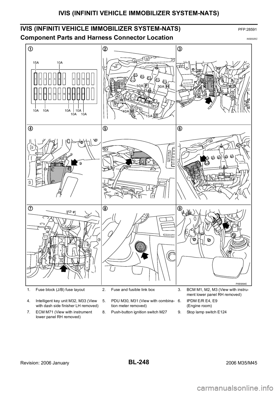
Component Parts and Harness Connector LocationNIS0020C
1. Fuse block (J/B) fuse layout 2. Fuse and fusible link box 3. BCM M1, M2, M3 (View with instru-
ment lower panel RH removed)
4. Intelligent key unit M32, M33 (View
with dash side finisher LH removed) 5. PDU M30, M31 (View with combina-
tion meter removed)6. IPDM E/R E4, E9
(Engine room)
7. ECM M71 (View with instrument
lower panel RH removed)8. Push-button ignition switch M27 9. Stop lamp switch E124
PIIB5894E
Page 1203 of 5621

BL-264
IVIS (INFINITI VEHICLE IMMOBILIZER SYSTEM-NATS)
Revision: 2006 January2006 M35/M45
Terminals and Reference Value for Intelligent Key UnitNIS0020I
Te r m i -
nal
No.Wire
colorItemCondition
Voltage (V)
(Approx.) Push-
button
ignition
switch
positionOperation or conditions
1 SB Power source (fuse) — — Battery voltage
3YIPDM E/R current sig-
nalSTART At starter motor cranking 5
LOCK Any condition other than above 2
8WPush-button ignition
switch LOCK indicatorLOCKPower supply position is in LOCK
position0
—Power supply position is in any posi-
tion other than LOCK1.2
9LPush-button ignition
switch ACC indicatorACCPower supply position is in ACC posi-
tion0
—Power supply position is in any posi-
tion other than ACC1.2
10 VPush-button ignition
switch ON indicatorONPower supply position is in ON posi-
tion0
—Power supply position is in any posi-
tion other than ON1.2
11 P Stop lamp switch —Brake pedal depressed Battery voltage
Brake pedal released Battery voltage
12 L/RPush-button ignition
switch illumination—Push-button ignition switch illumina-
tion is turned on2.6
Push-button ignition switch illumina-
tion is turned off
(15 seconds or more after the driver
door is closed)0
13 LG/B Key slot illumination LOCKDriver door is opened under the condi-
tion that the Intelligent Key is inserted
into the key slot0
Battery voltage 0
Intelligent Key is removed from key
slot (when key slot illumination is
turned off)0
15 LGSteering lock unit
power sourceLOCK — Battery voltage
16 P/BSteering lock unit sig-
nalLOCK Steering lock: Lock Battery voltage
ACCSteering lock: Unlock
(Unlocked moment)0
17 OSteering lock unit con-
dition signal-1LOCK Steering lock: Lock 0
ACC
Steering lock: UnlockBattery voltage
ON Battery voltage
18 L/YSteering lock unit con-
dition signal-2LOCK Steering lock: Lock Battery voltage
ACC
Steering lock: Unlock0
ON 0
19 BR/Y Key switch LOCKIntelligent Key is inserted into key slot Battery voltage
Intelligent Key is removed from key
slot0
20 B Ground — — 0
Page 1204 of 5621
IVIS (INFINITI VEHICLE IMMOBILIZER SYSTEM-NATS)
BL-265
C
D
E
F
G
H
J
K
L
MA
B
BL
Revision: 2006 January2006 M35/M45
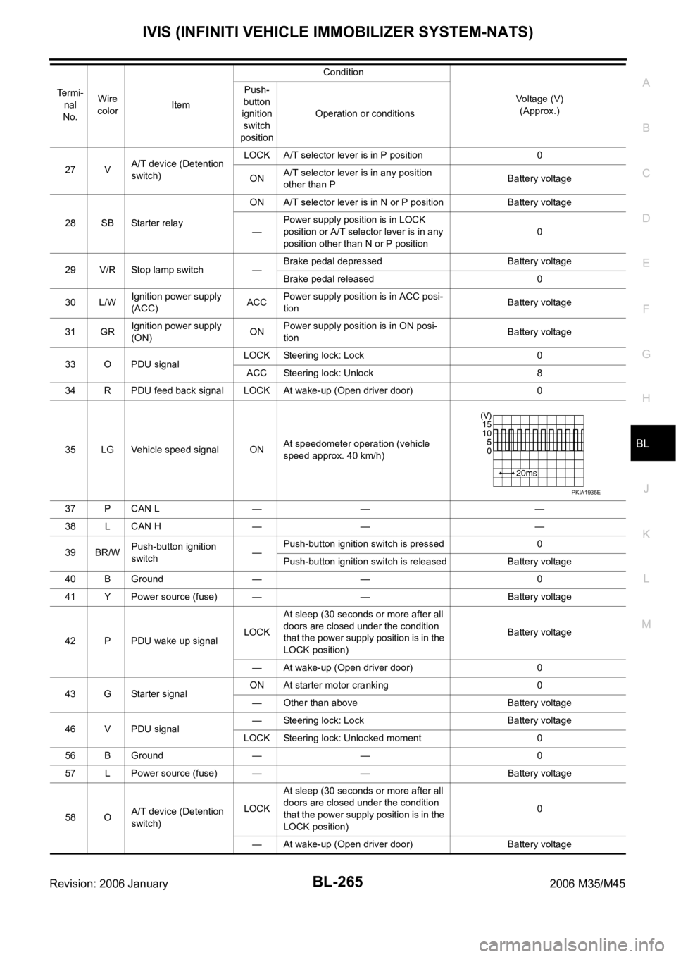
27 VA/T device (Detention
switch)LOCK A/T selector lever is in P position 0
ONA/T selector lever is in any position
other than PBattery voltage
28 SB Starter relayON A/T selector lever is in N or P position Battery voltage
—Power supply position is in LOCK
position or A/T selector lever is in any
position other than N or P position0
29 V/R Stop lamp switch —Brake pedal depressed Battery voltage
Brake pedal released 0
30 L/WIgnition power supply
(ACC)ACCPower supply position is in ACC posi-
tionBattery voltage
31 GRIgnition power supply
(ON)ONPower supply position is in ON posi-
tionBattery voltage
33 O PDU signalLOCK Steering lock: Lock 0
ACC Steering lock: Unlock 8
34 R PDU feed back signal LOCK At wake-up (Open driver door) 0
35 LG Vehicle speed signal ONAt speedometer operation (vehicle
speed approx. 40 km/h)
37 P CAN L — — —
38 L CAN H — — —
39 BR/WPush-button ignition
switch—Push-button ignition switch is pressed 0
Push-button ignition switch is released Battery voltage
40 B Ground — — 0
41 Y Power source (fuse) — — Battery voltage
42 P PDU wake up signalLOCKAt sleep (30 seconds or more after all
doors are closed under the condition
that the power supply position is in the
LOCK position)Battery voltage
— At wake-up (Open driver door) 0
43 G Starter signalON At starter motor cranking 0
— Other than above Battery voltage
46 V PDU signal— Steering lock: Lock Battery voltage
LOCK Steering lock: Unlocked moment 0
56 B Ground — — 0
57 L Power source (fuse) — — Battery voltage
58 OA/T device (Detention
switch)LOCKAt sleep (30 seconds or more after all
doors are closed under the condition
that the power supply position is in the
LOCK position)0
— At wake-up (Open driver door) Battery voltage Te r m i -
nal
No.Wire
colorItemCondition
Voltage (V)
(Approx.) Push-
button
ignition
switch
positionOperation or conditions
PKIA1935E
Page 1206 of 5621

IVIS (INFINITI VEHICLE IMMOBILIZER SYSTEM-NATS)
BL-267
C
D
E
F
G
H
J
K
L
MA
B
BL
Revision: 2006 January2006 M35/M45
Terminals and Reference Value for IPDM E/RNIS0020L
Terminals and Reference Value for PDUNIS0020M
38 WIgnition power supply
(ON or START)ONPower supply position is in ON posi-
tionBattery voltage
39 L CAN H — — —
40 P CAN L — — —
42 P Power source (fuse) — — Battery voltage
52 B Ground — — 0
55 WPower source (Fusible
link)— — Battery voltage Te r m i -
nal
No.Wire
colorItemCondition
Voltage (V)
(Approx.) Push-but-
ton igni-
tion
switch
positionOperation or conditions
Te r -
minal
No.Wire
ColorItemCondition
Voltage (V)
(Approx.) Push-
button
ignition
switch
positionOperation or conditions
4W/RStarter motor power
supplyLOCK — 0
START Starter motor is activating Battery voltage
49 L CAN H — — —
50 P CAN L — — —
53 GR/RA/T Shift position
signalONA/T shift position is P/ N posi-
tionBattery voltage
LOCK Other than above 0
Te r -
minal
No.Wire
colorItemCondition
Voltage (V)
(Approx.) Push-
button
ignition
switch
positionOperation or conditions
1 P Wake up signalLOCKSleep condition (30 seconds or more
after all doors are closed under the con-
dition that the power supply position is in
the LOCK position)Battery voltage
— Wake-up condition (Open driver door) 0
2 G Starter control signalON At starter motor cranking 0
— Any condition other than above Battery voltage
3GRSteering lock unit
power sourceLOCKPush-button ignition switch is pressed
under the condition that Intelligent Key is
in the vehicle or Intelligent Key is inserted0
Battery voltage 0
— Any condition other than above 0
Page 1207 of 5621

BL-268
IVIS (INFINITI VEHICLE IMMOBILIZER SYSTEM-NATS)
Revision: 2006 January2006 M35/M45
CONSULT-IINIS0020N
CONSULT-II INSPECTION PROCEDURE
1. Turn ignition switch OFF.
2. Insert IVIS (NATS) program card into CONSULT-II.
3. Connect CONSULT-II and CONSULT-II CONVERTER to data
link connector (1).
6VSteering lock control
signal-1—Push-button ignition switch is pressed
under the condition that Intelligent Key is
in the vehicle or Intelligent Key is insertedBattery voltage
LOCKPower supply position is in LOCK posi-
tion
(Steering lock activated)Battery voltage 0 Battery volt-
age
(Battery voltage is detected when
activating the steering lock)
7LGSteering lock control
signal-2—Push-button ignition switch is pressed
under the condition that Intelligent Key is
in the vehicle or Intelligent Key is insertedBattery voltage
LOCKPower supply position is in LOCK posi-
tion
(Steering lock activated)Battery voltage
0 Battery volt-
age
(Battery voltage is detected when
activating the steering lock)
9OSteering lock feed
back signal—Power supply position is in ACC or ON
position0
LOCKPower supply position is in LOCK posi-
tion0
8 0
(0V is detected when activating the
steering lock)
10 B Ground — — 0
11 YIPDM E/R current sig-
nalSTART At starter motor cranking 5
LOCK Any condition other than above 2
12 R Feed back signalLOCKSleep condition (30 seconds or more
after all doors are closed under the con-
dition that the power supply position is in
the LOCK position)1
—Wake-up condition (any condition other
than above)0
13 R Starter relaySTART At starter motor cranking Battery voltage
— Any condition other than above 4
14 SB Power source (fuse) — — Battery voltage
15 LPower source (fusible
link)— — Battery voltage
17 GPower source (fusible
link)— — Battery voltage Te r -
minal
No.Wire
colorItemCondition
Voltage (V)
(Approx.) Push-
button
ignition
switch
positionOperation or conditions
Program card : NATS (AEN04D)
PBIB2712E
Page 1217 of 5621
BL-278
IVIS (INFINITI VEHICLE IMMOBILIZER SYSTEM-NATS)
Revision: 2006 January2006 M35/M45
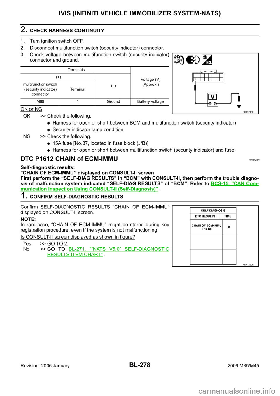
2. CHECK HARNESS CONTINUITY
1. Turn ignition switch OFF.
2. Disconnect multifunction switch (security indicator) connector.
3. Check voltage between multifunction switch (security indicator)
connector and ground.
OK or NG
OK >> Check the following.
Harness for open or short between BCM and multifunction switch (security indicator)
Security indicator lamp condition
NG >> Check the following.
15A fuse [No.37, located in fuse block (J/B)]
Harness for open or short between multifunction switch (security indicator) and fuse
DTC P1612 CHAIN of ECM-IMMUNIS0020S
Self-diagnostic results:
“CHAIN OF ECM-IMMU” displayed on CONSULT-II screen
First perform the “SELF-DIAG RESULTS” in “BCM” with CONSULT-II, then perform the trouble diagno-
sis of malfunction system indicated “SELF-DIAG RESULTS” of “BCM”. Refer to BCS-15, "
CAN Com-
munication Inspection Using CONSULT-II (Self-Diagnosis)" .
1. CONFIRM SELF-DIAGNOSTIC RESULTS
Confirm SELF-DIAGNOSTIC RESULTS “CHAIN OF ECM-IMMU”
displayed on CONSULT-II screen.
NOTE:
In rare case, “CHAIN OF ECM-IMMU” might be stored during key
registration procedure, even if the system is not malfunctioning.
Is CONSULT-II screen displayed as shown in figure?
Yes >> GO TO 2.
No >> GO TO BL-271, "
“NATS V5.0” SELF-DIAGNOSTIC
RESULTS ITEM CHART" .
Te r m i n a l s
Voltage (V)
(Approx.) (+)
(–) multifunction switch
(security indicator)
connectorTerminal
M69 1 Ground Battery voltage
PIIB6218E
PIIA1260E
Page 1218 of 5621
IVIS (INFINITI VEHICLE IMMOBILIZER SYSTEM-NATS)
BL-279
C
D
E
F
G
H
J
K
L
MA
B
BL
Revision: 2006 January2006 M35/M45
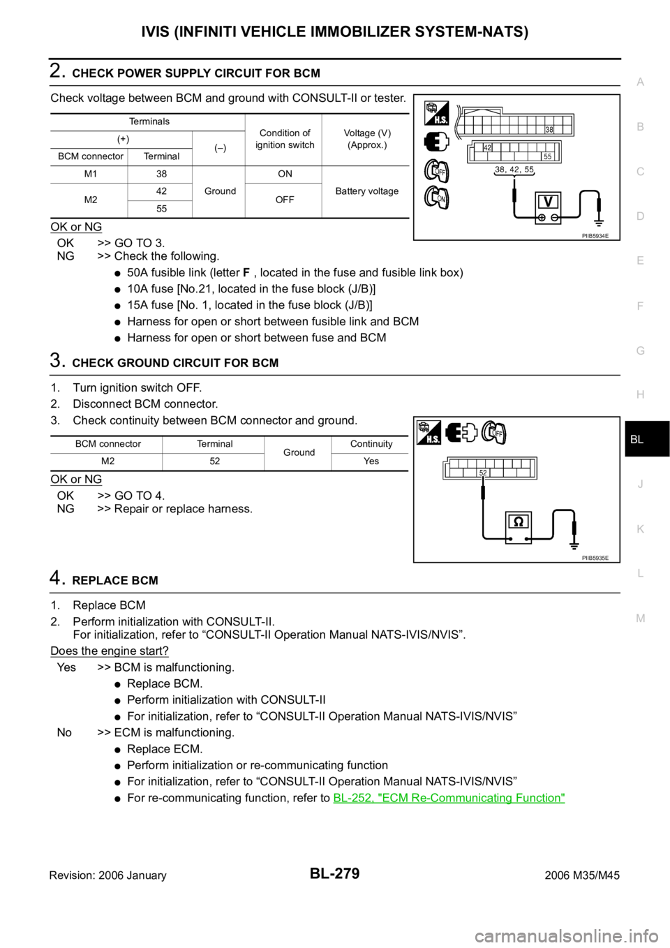
2. CHECK POWER SUPPLY CIRCUIT FOR BCM
Check voltage between BCM and ground with CONSULT-II or tester.
OK or NG
OK >> GO TO 3.
NG >> Check the following.
50A fusible link (letter F , located in the fuse and fusible link box)
10A fuse [No.21, located in the fuse block (J/B)]
15A fuse [No. 1, located in the fuse block (J/B)]
Harness for open or short between fusible link and BCM
Harness for open or short between fuse and BCM
3. CHECK GROUND CIRCUIT FOR BCM
1. Turn ignition switch OFF.
2. Disconnect BCM connector.
3. Check continuity between BCM connector and ground.
OK or NG
OK >> GO TO 4.
NG >> Repair or replace harness.
4. REPLACE BCM
1. Replace BCM
2. Perform initialization with CONSULT-II.
For initialization, refer to “CONSULT-II Operation Manual NATS-IVIS/NVIS”.
Does the engine start?
Yes >> BCM is malfunctioning.
Replace BCM.
Perform initialization with CONSULT-II
For initialization, refer to “CONSULT-II Operation Manual NATS-IVIS/NVIS”
No >> ECM is malfunctioning.
Replace ECM.
Perform initialization or re-communicating function
For initialization, refer to “CONSULT-II Operation Manual NATS-IVIS/NVIS”
For re-communicating function, refer to BL-252, "ECM Re-Communicating Function"
Terminals
Condition of
ignition switchVoltage (V)
(Approx.) (+)
(–)
BCM connector Terminal
M1 38
GroundON
Battery voltage
M242
OFF
55
PIIB5934E
BCM connector Terminal
GroundContinuity
M2 52 Yes
PIIB5935E
Page 1221 of 5621
BL-282
INTEGRATED HOMELINK TRANSMITTER
Revision: 2006 January2006 M35/M45
Trouble DiagnosesNIS0020W
DIAGNOSTIC PROCEDURE
SYMPTOM: Transmitter does not activate receiver.
Before conducting the procedure given below, make sure that system receiver (garage door opener, etc.)
operates with original, hand-held transmitter. If NG, receiver or hand-held transmitter is malfunctioning, not
vehicle related.
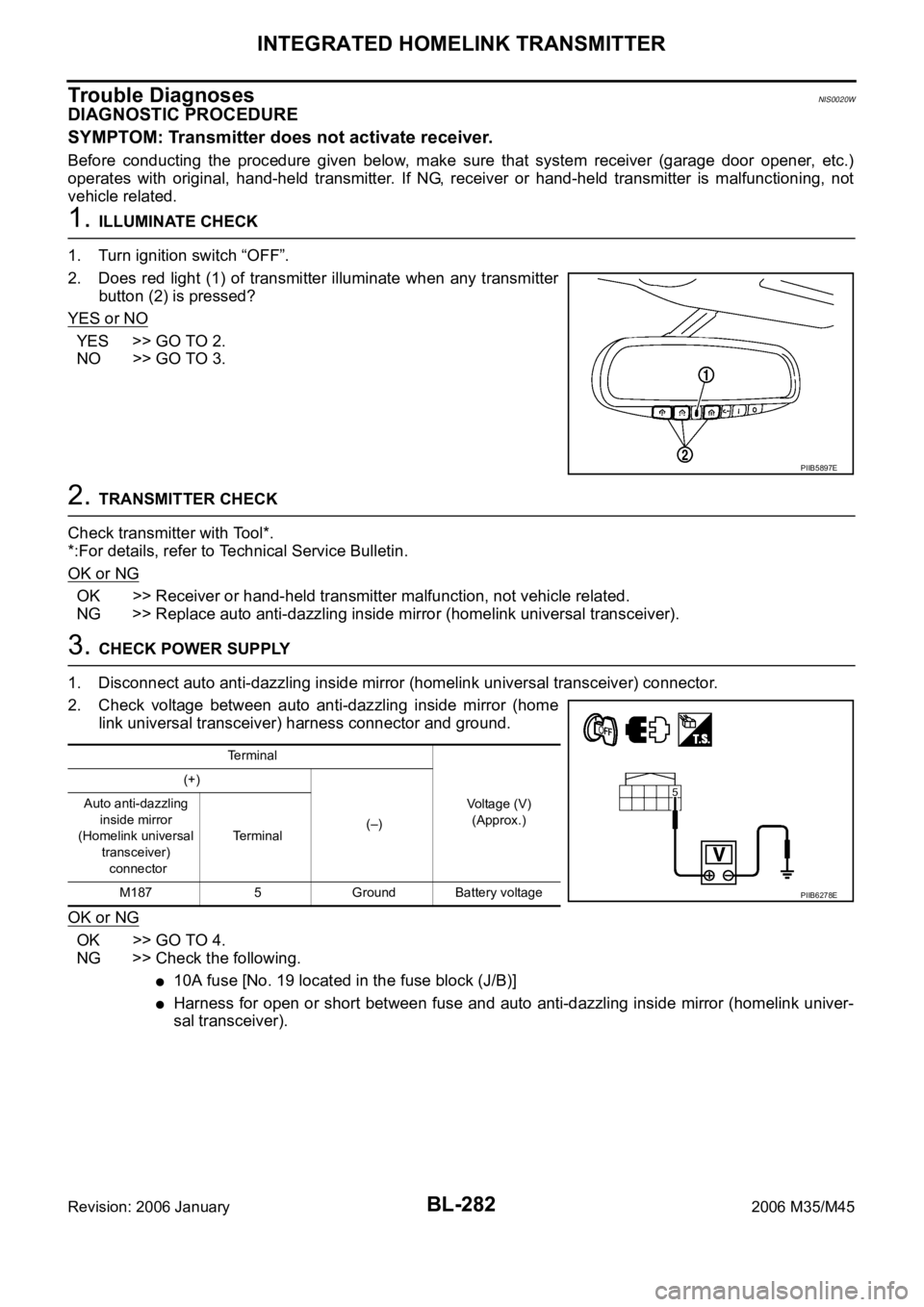
1. ILLUMINATE CHECK
1. Turn ignition switch “OFF”.
2. Does red light (1) of transmitter illuminate when any transmitter
button (2) is pressed?
YES or NO
YES >> GO TO 2.
NO >> GO TO 3.
2. TRANSMITTER CHECK
Check transmitter with Tool*.
*:For details, refer to Technical Service Bulletin.
OK or NG
OK >> Receiver or hand-held transmitter malfunction, not vehicle related.
NG >> Replace auto anti-dazzling inside mirror (homelink universal transceiver).
3. CHECK POWER SUPPLY
1. Disconnect auto anti-dazzling inside mirror (homelink universal transceiver) connector.
2. Check voltage between auto anti-dazzling inside mirror (home
link universal transceiver) harness connector and ground.
OK or NG
OK >> GO TO 4.
NG >> Check the following.
10A fuse [No. 19 located in the fuse block (J/B)]
Harness for open or short between fuse and auto anti-dazzling inside mirror (homelink univer-
sal transceiver).
PIIB5897E
Terminal
Voltage (V)
(Approx.) (+)
(–) Auto anti-dazzling
inside mirror
(Homelink universal
transceiver)
connectorTerminal
M187 5 Ground Battery voltage
PIIB6278E