2006 INFINITI M35 Fuse
[x] Cancel search: FusePage 1438 of 5621

COMBINATION METERS
DI-5
C
D
E
F
G
H
I
J
L
MA
B
DI
Revision: 2006 January2006 M35/M45
COMBINATION METERSPFP:24814
System DescriptionNKS003TV
UNIFIED METER CONTROL UNIT
Speedometer, odo/trip meter, tachometer, fuel gauge and water temperature gauge are controlled by the
unified meter control unit, which is built into the combination meter. Unified meter control unit receives sig-
nals from unified meter and A/C amp.
Warning lamp and indicator lamp of combination meter are controlled by signals drawn from the unified
meter and A/C amp.
Digital meter is adopted for odo/trip meter.
NOTE:
The record of the odo meter is kept even if the battery cable is disconnected. The record of the trip meter
is erased when the battery cable is disconnected.
Dot matrix LCD is adopted to display “push engine starter”, “A/T position” and “ICC system* ”.
Odo/trip meter and dot matrix LCD segments can be checked in self-diagnosis mode.
Meters/gauges can be checked in self-diagnosis mode.
*: With ICC system
UNIFIED METER AND A/C AMP.
Refer to DI-28, "COMBINATION METER CONTROL FUNCTION" in “UNIFIED METER AND A/C AMP”.
POWER SUPPLY AND GROUND CIRCUIT
Power is supplied at all times
through 10A fuse [No. 21, located in the fuse block (J/B)]
to combination meter terminal 23,
through 10A fuse [No. 19, located in the fuse block (J/B)]
to unified meter and A/C amp. terminal 54.
With the ignition switch in the ACC or ON position, power is supplied
through 10A fuse [No. 6, located in the fuse block (J/B)],
to combination meter terminal 2, and
to unified meter and A/C amp. terminal 41.
With the ignition switch in the ON or START position, power is supplied
through 10A fuse [No. 14, located in the fuse block (J/B)]
to combination meter terminal 12,
through 10A fuse [No. 12, located in the fuse block (J/B)]
to unified meter and A/C amp. terminal 53.
Ground is supplied
to combination meter terminals 9, 10 and 11
to unified meter and A/C amp. terminals 55 and 71
through grounds M16 and M70.
Page 1452 of 5621
COMBINATION METERS
DI-19
C
D
E
F
G
H
I
J
L
MA
B
DI
Revision: 2006 January2006 M35/M45
Power Supply and Ground Circuit InspectionNKS003U6
1. CHECK FUSE
Check for blown fuses.
OK or NG
OK >> GO TO 2.
NG >> Be sure to eliminate cause of malfunction before installing new fuse. Refer to PG-3, "
POWER
SUPPLY ROUTING CIRCUIT" .
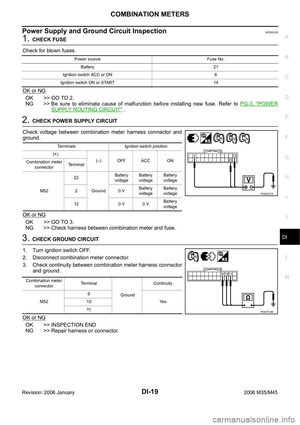
2. CHECK POWER SUPPLY CIRCUIT
Check voltage between combination meter harness connector and
ground.
OK or NG
OK >> GO TO 3.
NG >> Check harness between combination meter and fuse.
3. CHECK GROUND CIRCUIT
1. Turn ignition switch OFF.
2. Disconnect combination meter connector.
3. Check continuity between combination meter harness connector
and ground.
OK or NG
OK >> INSPECTION END
NG >> Repair harness or connector.
Power source Fuse No.
Battery 21
Ignition switch ACC or ON 6
Ignition switch ON or START 14
Terminals Ignition switch position
(+)
(–) OFF ACC ON
Combination meter
connectorTerminal
M5223
GroundBattery
voltageBattery
voltageBattery
voltage
20 VBattery
voltageBattery
voltage
12 0 V 0 VBattery
voltage
PKIB7637E
Combination meter
connectorTerminal
GroundContinuity
M529
Ye s 10
11
PKIB7638E
Page 1465 of 5621
DI-32
UNIFIED METER AND A/C AMP
Revision: 2006 January2006 M35/M45
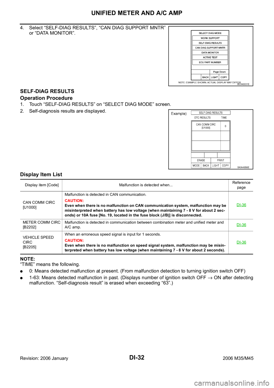
4. Select “SELF-DIAG RESULTS”, “CAN DIAG SUPPORT MNTR”
or “DATA MONITOR”.
SELF-DIAG RESULTS
Operation Procedure
1. Touch “SELF-DIAG RESULTS” on “SELECT DIAG MODE” screen.
2. Self-diagnosis results are displayed.
Display Item List
NOTE:
“TIME” means the following.
0: Means detected malfunction at present. (From malfunction detection to turning ignition switch OFF)
1-63: Means detected malfunction in past. (Displays number of ignition switch OFF ON after detecting
malfunction. “Self-diagnosis result” is erased when exceeding “63”.)
BCIA0031E
SKIA4956E
Display item [Code] Malfunction is detected when...Reference
page
CAN COMM CIRC
[U1000]Malfunction is detected in CAN communication.
CAUTION:
Even when there is no malfunction on CAN communication system, malfunction may be
misinterpreted when battery has low voltage (when maintaining 7 - 8 V for about 2 sec-
onds) or 10A fuse [No. 19, located in the fuse block (J/B)] is disconnected.DI-36
METER COMM CIRC
[B2202]Malfunction is detected in communication between combination meter and unified meter and
A/C amp.DI-36
VEHICLE SPEED
CIRC
[B2205]When an erroneous speed signal is input for 1 seconds.
CAUTION:
Even when there is no malfunction on speed signal system, malfunction may be misin-
terpreted when battery has low voltage (when maintaining 7 - 8 V for about 2 seconds). DI-36
Page 1468 of 5621
UNIFIED METER AND A/C AMP
DI-35
C
D
E
F
G
H
I
J
L
MA
B
DI
Revision: 2006 January2006 M35/M45
Power Supply and Ground Circuit InspectionNKS003UJ
1. CHECK FUSE
Check for blown fuses.
OK or NG
OK >> GO TO 2.
NG >> Be sure to eliminate cause of malfunction before installing new fuse. Refer to PG-3, "
POWER
SUPPLY ROUTING CIRCUIT" .
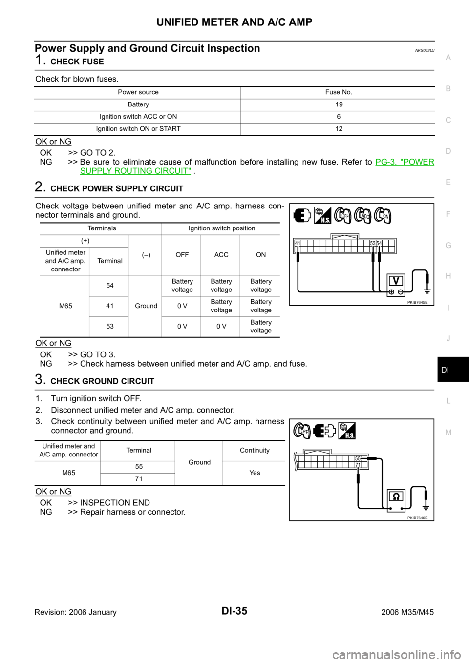
2. CHECK POWER SUPPLY CIRCUIT
Check voltage between unified meter and A/C amp. harness con-
nector terminals and ground.
OK or NG
OK >> GO TO 3.
NG >> Check harness between unified meter and A/C amp. and fuse.
3. CHECK GROUND CIRCUIT
1. Turn ignition switch OFF.
2. Disconnect unified meter and A/C amp. connector.
3. Check continuity between unified meter and A/C amp. harness
connector and ground.
OK or NG
OK >> INSPECTION END
NG >> Repair harness or connector.
Power source Fuse No.
Battery 19
Ignition switch ACC or ON 6
Ignition switch ON or START 12
Terminals Ignition switch position
(+)
(–) OFF ACC ON Unified meter
a n d A / C a m p .
connectorTerminal
M6554
GroundBattery
voltageBattery
voltageBattery
voltage
41 0 VBattery
voltageBattery
voltage
53 0 V 0 VBattery
voltage
PKIB7645E
Unified meter and
A/C amp. connectorTerminal
GroundContinuity
M6555
Ye s
71
PKIB7646E
Page 1472 of 5621
UNIFIED METER AND A/C AMP
DI-39
C
D
E
F
G
H
I
J
L
MA
B
DI
Revision: 2006 January2006 M35/M45
7. CHECK COMMUNICATION SIGNAL (RX: UNIFIED METER AND A/C AMP.)
1. Turn ignition switch OFF.
2. Connect combination meter connector.
3. Turn ignition switch ON.
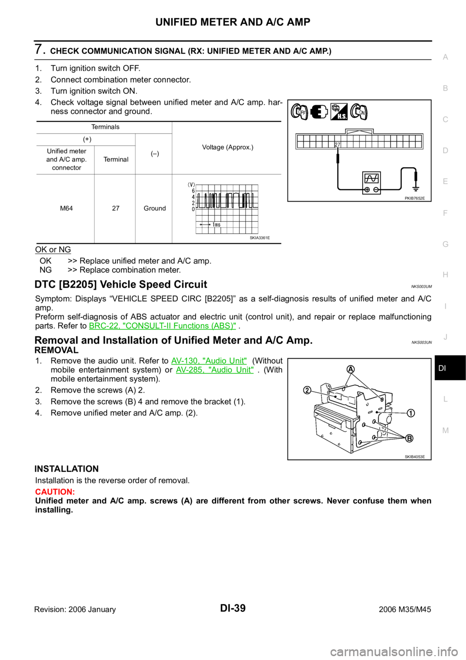
4. Check voltage signal between unified meter and A/C amp. har-
ness connector and ground.
OK or NG
OK >> Replace unified meter and A/C amp.
NG >> Replace combination meter.
DTC [B2205] Vehicle Speed CircuitNKS003UM
Symptom: Displays “VEHICLE SPEED CIRC [B2205]” as a self-diagnosis results of unified meter and A/C
amp.
Preform self-diagnosis of ABS actuator and electric unit (control unit), and repair or replace malfunctioning
parts. Refer to BRC-22, "
CONSULT-II Functions (ABS)" .
Removal and Installation of Unified Meter and A/C Amp. NKS003UN
REMOVAL
1. Remove the audio unit. Refer to AV- 1 3 0 , "Audio Unit" (Without
mobile entertainment system) or AV- 2 8 5 , "
Audio Unit" . (With
mobile entertainment system).
2. Remove the screws (A) 2.
3. Remove the screws (B) 4 and remove the bracket (1).
4. Remove unified meter and A/C amp. (2).
INSTALLATION
Installation is the reverse order of removal.
CAUTION:
Unified meter and A/C amp. screws (A) are different from other screws. Never confuse them when
installing.
Terminals
Voltage (Approx.) (+)
(–) Unified meter
and A/C amp.
connectorTerminal
M64 27 Ground
PKIB7652E
SKIA3361E
SKIB4053E
Page 1493 of 5621
DI-60
WARNING CHIME
Revision: 2006 January2006 M35/M45
WARNING CHIMEPFP:24814
System DescriptionNKS003UY
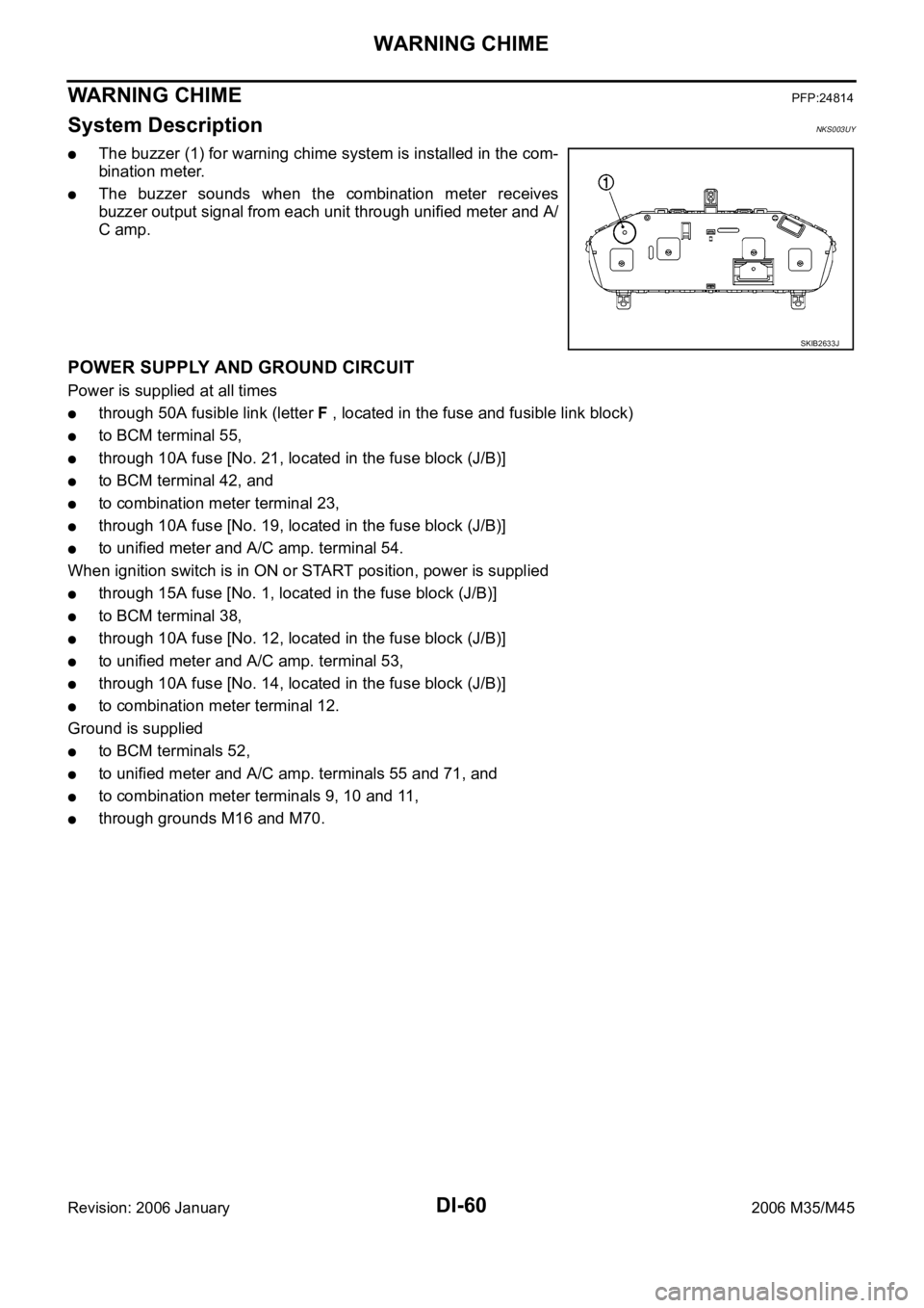
The buzzer (1) for warning chime system is installed in the com-
bination meter.
The buzzer sounds when the combination meter receives
buzzer output signal from each unit through unified meter and A/
C amp.
POWER SUPPLY AND GROUND CIRCUIT
Power is supplied at all times
through 50A fusible link (letter F , located in the fuse and fusible link block)
to BCM terminal 55,
through 10A fuse [No. 21, located in the fuse block (J/B)]
to BCM terminal 42, and
to combination meter terminal 23,
through 10A fuse [No. 19, located in the fuse block (J/B)]
to unified meter and A/C amp. terminal 54.
When ignition switch is in ON or START position, power is supplied
through 15A fuse [No. 1, located in the fuse block (J/B)]
to BCM terminal 38,
through 10A fuse [No. 12, located in the fuse block (J/B)]
to unified meter and A/C amp. terminal 53,
through 10A fuse [No. 14, located in the fuse block (J/B)]
to combination meter terminal 12.
Ground is supplied
to BCM terminals 52,
to unified meter and A/C amp. terminals 55 and 71, and
to combination meter terminals 9, 10 and 11,
through grounds M16 and M70.
SKIB2633J
Page 1513 of 5621
DI-80
LANE DEPARTURE WARNING SYSTEM
Revision: 2006 January2006 M35/M45
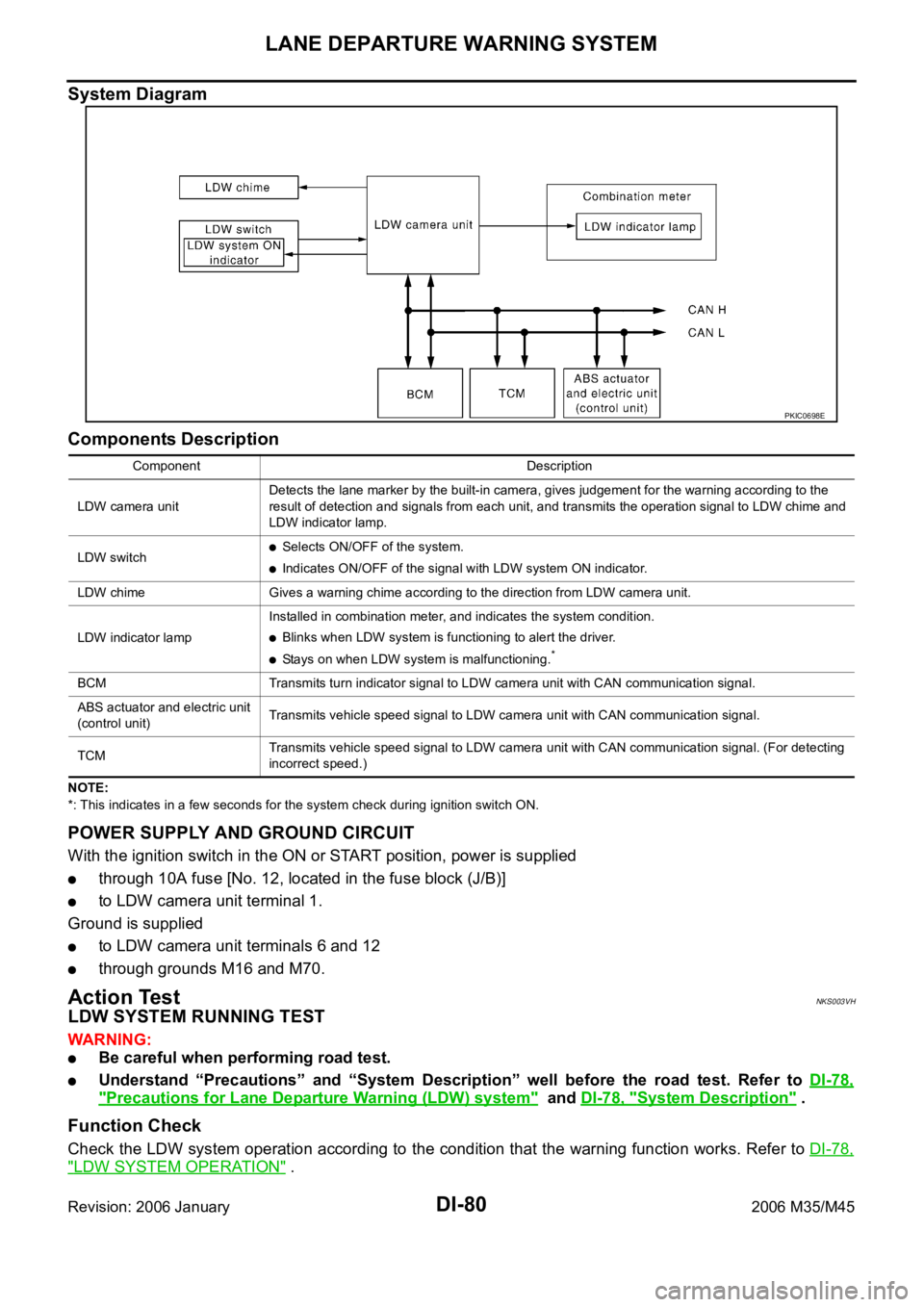
System Diagram
Components Description
NOTE:
*: This indicates in a few seconds for the system check during ignition switch ON.
POWER SUPPLY AND GROUND CIRCUIT
With the ignition switch in the ON or START position, power is supplied
through 10A fuse [No. 12, located in the fuse block (J/B)]
to LDW camera unit terminal 1.
Ground is supplied
to LDW camera unit terminals 6 and 12
through grounds M16 and M70.
Action TestNKS003VH
LDW SYSTEM RUNNING TEST
WAR NING :
Be careful when performing road test.
Understand “Precautions” and “System Description” well before the road test. Refer to DI-78,
"Precautions for Lane Departure Warning (LDW) system" and DI-78, "System Description" .
Function Check
Check the LDW system operation according to the condition that the warning function works. Refer to DI-78,
"LDW SYSTEM OPERATION" .
PKIC0698E
Component Description
LDW camera unitDetects the lane marker by the built-in camera, gives judgement for the warning according to the
result of detection and signals from each unit, and transmits the operation signal to LDW chime and
LDW indicator lamp.
LDW switch
Selects ON/OFF of the system.
Indicates ON/OFF of the signal with LDW system ON indicator.
LDW chime Gives a warning chime according to the direction from LDW camera unit.
LDW indicator lampInstalled in combination meter, and indicates the system condition.
Blinks when LDW system is functioning to alert the driver.
Stays on when LDW system is malfunctioning.*
BCM Transmits turn indicator signal to LDW camera unit with CAN communication signal.
ABS actuator and electric unit
(control unit)Transmits vehicle speed signal to LDW camera unit with CAN communication signal.
TCM Transmits vehicle speed signal to LDW camera unit with CAN communication signal. (For detecting
incorrect speed.)
Page 1529 of 5621
DI-96
LANE DEPARTURE WARNING SYSTEM
Revision: 2006 January2006 M35/M45
SYMPTOM CHART
Power Supply and Ground Circuit InspectionNKS003VO
1. CHECK FUSE
Check for blown LDW camera unit fuse.
OK or NG
OK >> GO TO 2.
NG >> Be sure to eliminate cause of malfunction before installing new fuse. Refer to PG-3, "
POWER
SUPPLY ROUTING CIRCUIT" .
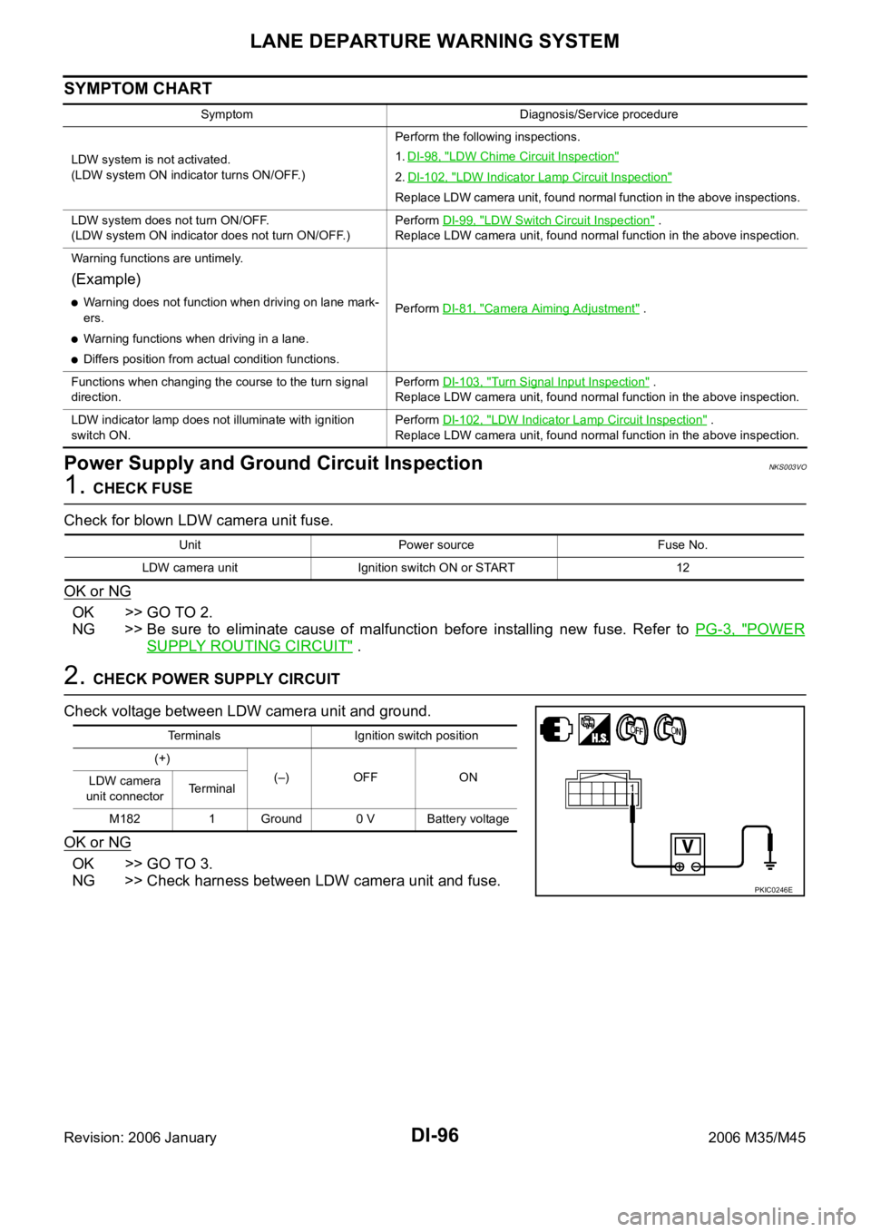
2. CHECK POWER SUPPLY CIRCUIT
Check voltage between LDW camera unit and ground.
OK or NG
OK >> GO TO 3.
NG >> Check harness between LDW camera unit and fuse.
Symptom Diagnosis/Service procedure
LDW system is not activated.
(LDW system ON indicator turns ON/OFF.)Perform the following inspections.
1.DI-98, "
LDW Chime Circuit Inspection"
2.DI-102, "LDW Indicator Lamp Circuit Inspection"
Replace LDW camera unit, found normal function in the above inspections.
LDW system does not turn ON/OFF.
(LDW system ON indicator does not turn ON/OFF.)Perform DI-99, "
LDW Switch Circuit Inspection" .
Replace LDW camera unit, found normal function in the above inspection.
Warning functions are untimely.
(Example)
Warning does not function when driving on lane mark-
ers.
Warning functions when driving in a lane.
Differs position from actual condition functions.Perform DI-81, "
Camera Aiming Adjustment" .
Functions when changing the course to the turn signal
direction.Perform DI-103, "
Turn Signal Input Inspection" .
Replace LDW camera unit, found normal function in the above inspection.
LDW indicator lamp does not illuminate with ignition
switch ON.Perform DI-102, "
LDW Indicator Lamp Circuit Inspection" .
Replace LDW camera unit, found normal function in the above inspection.
Unit Power source Fuse No.
LDW camera unit Ignition switch ON or START 12
Terminals Ignition switch position
(+)
(–) OFF ON
LDW camera
unit connectorTerminal
M182 1 Ground 0 V Battery voltage
PKIC0246E