2006 INFINITI M35 ECO mode
[x] Cancel search: ECO modePage 3507 of 5621
GI-44
TOW TRUCK TOWING
Revision: 2006 January2006 M35/M45
TOW TRUCK TOWINGPFP:00000
Tow Truck TowingNAS00081
CAUTION:
All applicable state or Provincial (in Canada) laws and local laws regarding the towing operation
must be obeyed.
It is necessary to use proper towing equipment to avoid possible damage to the vehicle during
towing operation. Towing is in accordance with Towing Procedure Manual at dealer.
Always attach safety chains before towing.
When towing, make sure that the transmission, steering system and powertrain are in good order.
If any unit is damaged, dollies must be used.
Never tow an automatic transmission model from the rear (that is backward) with four wheels on
the ground. This may cause serious and expensive damage to the transmission.
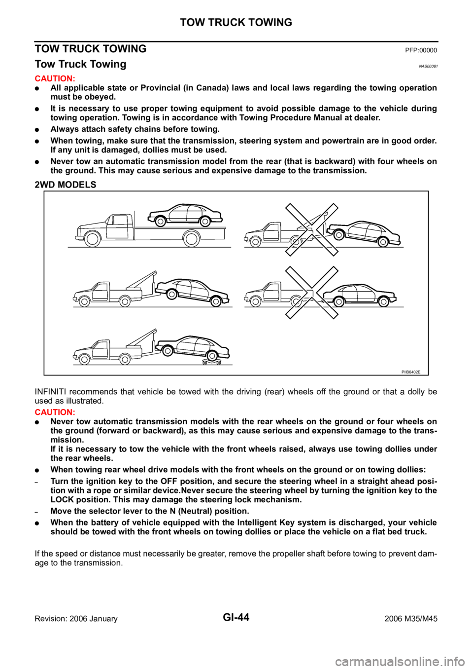
2WD MODELS
INFINITI recommends that vehicle be towed with the driving (rear) wheels off the ground or that a dolly be
used as illustrated.
CAUTION:
Never tow automatic transmission models with the rear wheels on the ground or four wheels on
the ground (forward or backward), as this may cause serious and expensive damage to the trans-
mission.
If it is necessary to tow the vehicle with the front wheels raised, always use towing dollies under
the rear wheels.
When towing rear wheel drive models with the front wheels on the ground or on towing dollies:
–Turn the ignition key to the OFF position, and secure the steering wheel in a straight ahead posi-
tion with a rope or similar device.Never secure the steering wheel by turning the ignition key to the
LOCK position. This may damage the steering lock mechanism.
–Move the selector lever to the N (Neutral) position.
When the battery of vehicle equipped with the Intelligent Key system is discharged, your vehicle
should be towed with the front wheels on towing dollies or place the vehicle on a flat bed truck.
If the speed or distance must necessarily be greater, remove the propeller shaft before towing to prevent dam-
age to the transmission.
PIIB6402E
Page 3508 of 5621
TOW TRUCK TOWING
GI-45
C
D
E
F
G
H
I
J
K
L
MB
GI
Revision: 2006 January2006 M35/M45
AWD MODELS
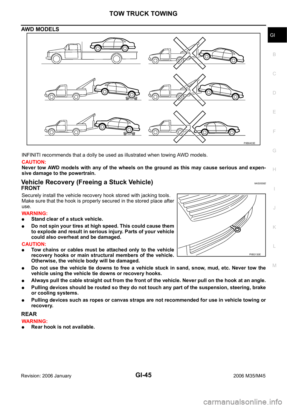
INFINITI recommends that a dolly be used as illustrated when towing AWD models.
CAUTION:
Never tow AWD models with any of the wheels on the ground as this may cause serious and expen-
sive damage to the powertrain.
Vehicle Recovery (Freeing a Stuck Vehicle) NAS00082
FRONT
Securely install the vehicle recovery hook stored with jacking tools.
Make sure that the hook is properly secured in the stored place after
use.
WAR NING :
Stand clear of a stuck vehicle.
Do not spin your tires at high speed. This could cause them
to explode and result in serious injury. Parts of your vehicle
could also overheat and be damaged.
CAUTION:
Tow chains or cables must be attached only to the vehicle
recovery hooks or main structural members of the vehicle.
Otherwise, the vehicle body will be damaged.
Do not use the vehicle tie downs to free a vehicle stuck in sand, snow, mud, etc. Never tow the
vehicle using the vehicle tie downs or recovery hooks.
Always pull the cable straight out from the front of the vehicle. Never pull on the hook at an angle.
Pulling devices should be routed so they do not touch any part of the suspension, steering, brake
or cooling systems.
Pulling devices such as ropes or canvas straps are not recommended for use in vehicle towing or
recovery.
REAR
WAR NING :
Rear hook is not available.
PIIB6403E
PIIB3130E
Page 3575 of 5621
GW-56
POWER WINDOW SYSTEM
Revision: 2006 January2006 M35/M45
Power Window Serial Link Check (Passenger Side)NIS00223
1. CHECK POWER WINDOW SWITCH OUTPUT SIGNAL
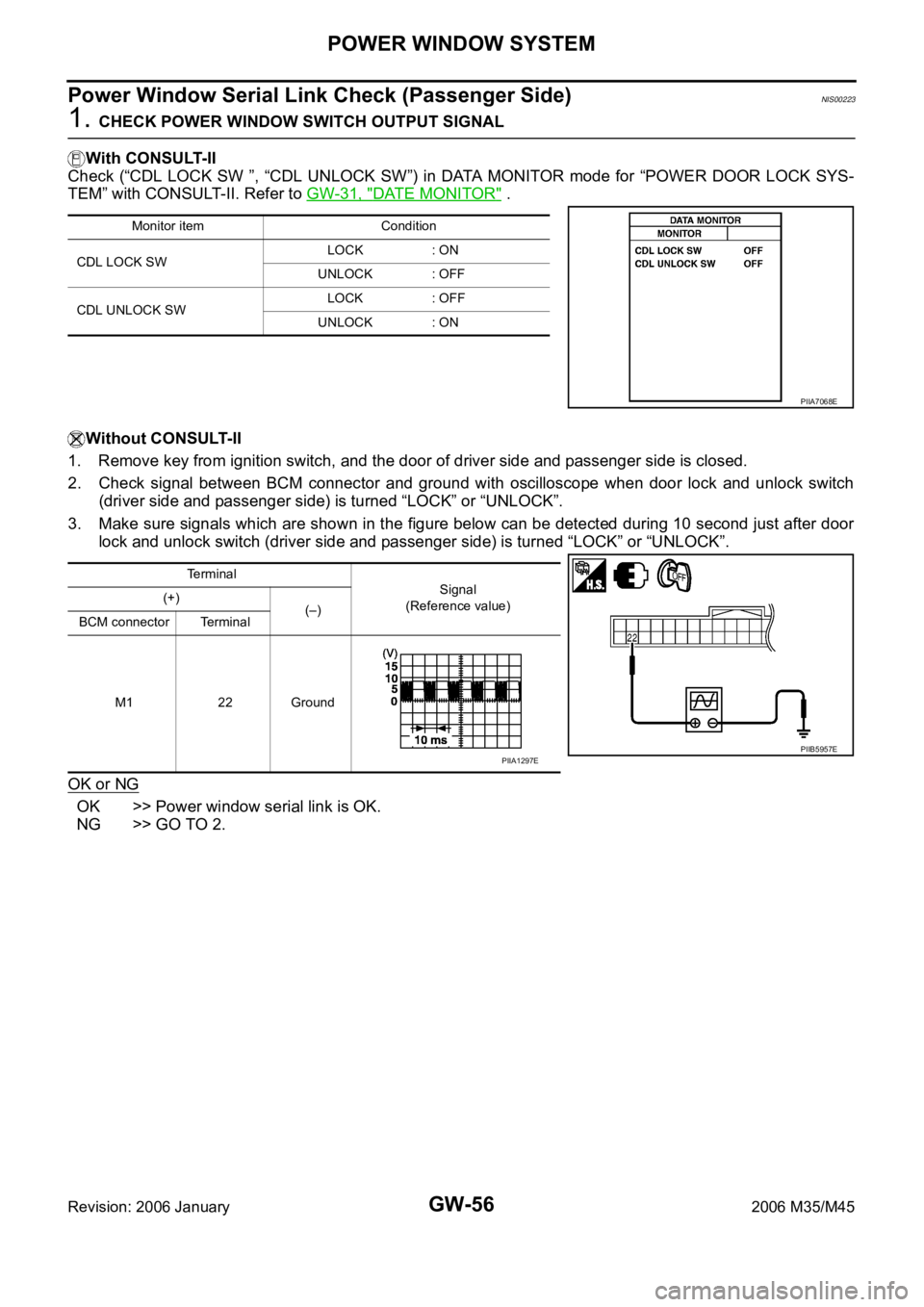
With CONSULT-II
Check (“CDL LOCK SW ”, “CDL UNLOCK SW”) in DATA MONITOR mode for “POWER DOOR LOCK SYS-
TEM” with CONSULT-II. Refer to GW-31, "
DATE MONITOR" .
Without CONSULT-II
1. Remove key from ignition switch, and the door of driver side and passenger side is closed.
2. Check signal between BCM connector and ground with oscilloscope when door lock and unlock switch
(driver side and passenger side) is turned “LOCK” or “UNLOCK”.
3. Make sure signals which are shown in the figure below can be detected during 10 second just after door
lock and unlock switch (driver side and passenger side) is turned “LOCK” or “UNLOCK”.
OK or NG
OK >> Power window serial link is OK.
NG >> GO TO 2.
Monitor item Condition
CDL LOCK SW LOCK : ON
UNLOCK : OFF
CDL UNLOCK SW LOCK : OFF
UNLOCK : ON
PIIA7068E
Terminal
Signal
(Reference value) (+)
(–)
BCM connector Terminal
M1 22 Ground
PIIB5957EPIIA1297E
Page 3647 of 5621
IDX-6
ALPHABETICAL INDEX
Meter ..................................................................... DI-5
METER - Wiring diagram .................................... DI-13
MIL data link connectors circuit ....... EC-722, EC-1459
MIL/DL - Wiring diagram .................. EC-722, EC-1459
MIRROR - Wiring diagram ................................ GW-99
Mirror, door ..................................................... GW-120
Mirror, out side ................................................ GW-120
Misfire .............................................. EC-361, EC-1084
MMSW - Wiring diagram .................................. AT-168
Mode door control linkage adjustment ATC-79, ATC-82
Mode door motor .............. ATC-75, ATC-80, ATC-140
Molding - See Exterior .............................. EI-25, EI-29
Mud guard - See Exterior .................................... EI-22
Multiport fuel injection (MFI) system .... EC-31, EC-741
Multiport fuel injection precautions ....................... GI-7
N
NATS - Wiring diagram .................................... BL-256
NONDTC - Wiring diagram .............................. AT-187
NVH troubleshooting (EM) .............................. EM-171
NVH troubleshooting (EM)(VQ35DE) ............... EM-12
NVH troubleshooting (Final drive) ......... FFD-6, RFD-7
NVH troubleshooting (Propeller shaft) ................. PR-3
NVH troubleshooting (Transfer) ........................... TF-8
NVIS (Nissan vehicle immobilizer system) precautions
GI-3
O
O2H2B1 - Wiring diagram .................. EC-191
, EC-913
O2H2B2 - Wiring diagram .................. EC-193, EC-915
O2S2B1 - Wiring diagram .. EC-289, EC-300, EC-313,
EC-1012
, EC-1023, EC-1036
O2S2B2 - Wiring diagram .. EC-291, EC-302, EC-315,
EC-1014
, EC-1025, EC-1038
Oil cooler (engine)(VQ35DE) ............................. LU-14
Oil filter(VK45DE) .............................................. LU-29
Oil filter(VQ35DE) .............................................. LU-10
Oil pan (engine)(VK45DE) .............................. EM-187
Oil pan (engine)(VQ35DE) ................................ EM-29
Oil pressure (engine)(VK45DE) ......................... LU-26
Oil pressure (engine)(VQ35DE) ........................... LU-8
Oil pressure relief valve (engine)(VQ35DE) ........ LU-6
Oil pump (A/T) ................................................. AT-318
Oil pump (engine)(VK45DE) .............................. LU-30
Oil pump (engine)(VQ35DE) .............................. LU-18
Oil pump regulator valve (engine)(VK45DE) ..... LU-30
Oil pump regulator valve (engine)(VQ35DE) ..... LU-18
Oil seal replacement (engine)(VK45DE) ......... EM-229
Oil seal replacement (engine)(VQ35DE) .......... EM-98
Oil seal replacement (front of final drive) .......... FFD-9,
RFD-10
Oil seal replacement (side of final drive) ......... FFD-11,
RFD-14
On board diagnostic system ................ EC-54, EC-764
ORVR (On-board Refueling Vapor Recovery) .. EC-46,
EC-756
Out side mirror ................................................ GW-120
Overheat ......................................... EC-512, EC-1239
P
P/SCKT - Wiring diagram ................................ WW-51
Park/Neutral position switch ........... EC-504, EC-1223
Park/neutral position switch (A/T) .................... AT-113
Parking brake control ........................................... PB-3
Parking lamp .................................................... LT-249
PCV (positive crankcase ventilation) .. EC-51, EC-761
PGC/V - Wiring diagram .. EC-414, EC-422, EC-1134,
EC-1142
PHASE - Wiring diagram ............................... EC-1108
PHSB1 - Wiring diagram .................................. EC-385
PHSB2 - Wiring diagram .................................. EC-387
Pilot bushing replacement - See Pilot
converter(VQ35DE) ........................................ EM-124
Piston assembly(VK45DE) ............................. EM-260
Piston assembly(VQ35DE) ............................. EM-135
Piston pin inspection(VK45DE) ....................... EM-266
Piston pin inspection(VQ35DE) ...................... EM-140
Piston ring inspection(VK45DE) ..................... EM-267
Piston ring inspection(VQ35DE) ..................... EM-141
Piston to bore clearance(VK45DE) ................. EM-270
Piston to bore clearance(VQ35DE) ................ EM-144
PNP/SW - Wiring diagram . EC-506, EC-1225, AT-114
POS - Wiring diagram ..................... EC-378, EC-1101
POWER - Wiring diagram ................................... PG-5
Power door mirror .............................................. BL-24
Power socket ................................................... WW-51
Power steering fluid level ........................ PS-8, MA-37
Power steering gear ........................................... PS-18
Power steering hydraulic pressure .................... PS-29
Power steering oil pump .................................... PS-29
Power steering system bleeding .......................... PS-8
Power supply routing .......................................... PG-3
Power window .................................................. GW-13
PRE/SE - Wiring diagram EC-445, EC-452, EC-1165,
EC-1172
Precations for Leak detection dye .................. ATC-15
Precautions (General) ........................................... GI-4
Pressure switch 1 .............................. AT-153, AT-172
Pressure switch 2 ............................................ AT-165
Pressure switch 3 .............................. AT-149, AT-174
Pressure switch 5 .............................. AT-157, AT-176
Pressure switch 6 .............................. AT-161, AT-178
Pressure test (A/T) ............................................. AT-55
Propeller shaft ........................................... PR-4, PR-6
Propeller shaft on vehicle service ............. PR-4, PR-6
Propeller shaft vibration ............................ PR-4, PR-6
PS/SEN - Wiring diagram ............... EC-488, EC-1207
R
Radiator(VK45DE) ............................................ CO-43
Radiator(VQ35DE) ............................................ CO-14
Rear axle .......................................................... RAX-5
Rear bumper ....................................................... EI-14
Rear combination lamp removal and installation ..........
Page 4450 of 5621
HEADLAMP (FOR USA) - CONVENTIONAL TYPE -
LT-23
C
D
E
F
G
H
I
J
L
MA
B
LT
Revision: 2006 January2006 M35/M45
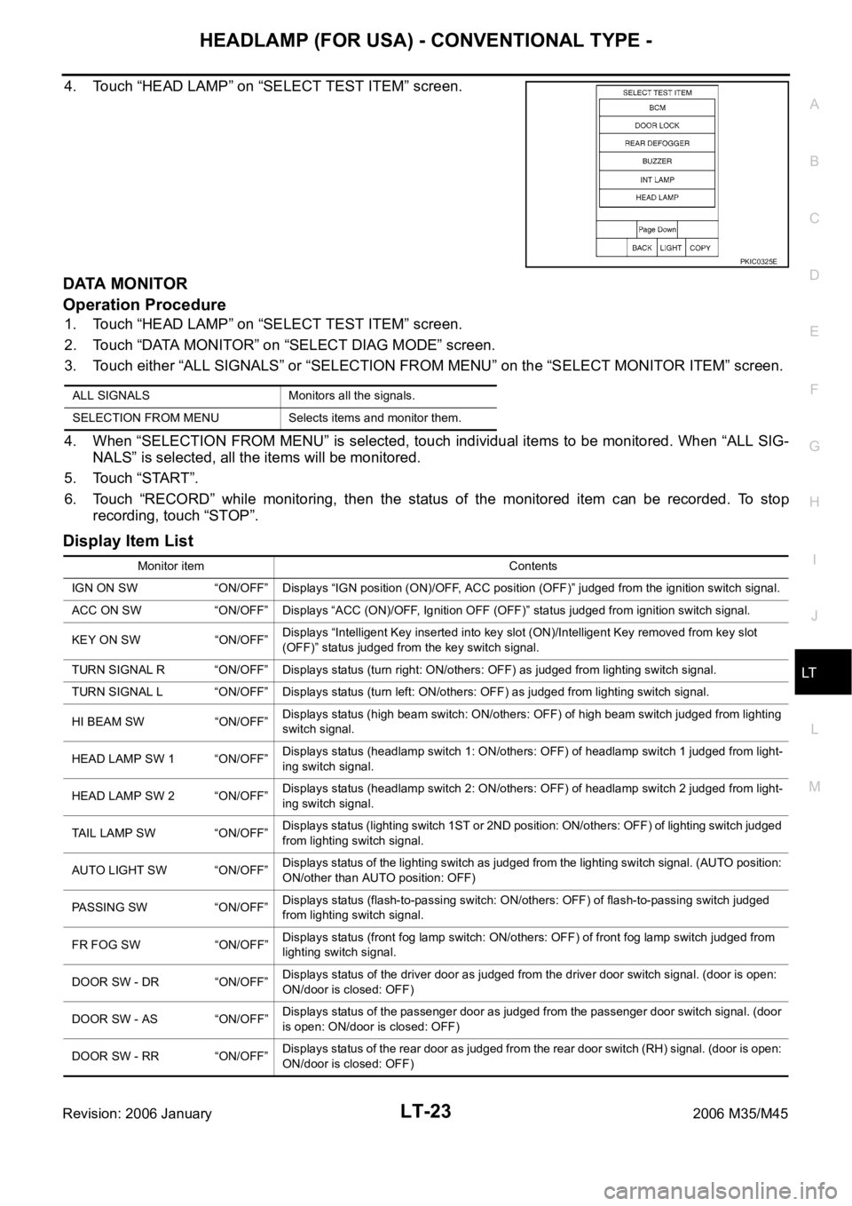
4. Touch “HEAD LAMP” on “SELECT TEST ITEM” screen.
DATA MONITOR
Operation Procedure
1. Touch “HEAD LAMP” on “SELECT TEST ITEM” screen.
2. Touch “DATA MONITOR” on “SELECT DIAG MODE” screen.
3. Touch either “ALL SIGNALS” or “SELECTION FROM MENU” on the “SELECT MONITOR ITEM” screen.
4. When “SELECTION FROM MENU” is selected, touch individual items to be monitored. When “ALL SIG-
NALS” is selected, all the items will be monitored.
5. Touch “START”.
6. Touch “RECORD” while monitoring, then the status of the monitored item can be recorded. To stop
recording, touch “STOP”.
Display Item List
PKIC0325E
ALL SIGNALS Monitors all the signals.
SELECTION FROM MENU Selects items and monitor them.
Monitor item Contents
IGN ON SW “ON/OFF” Displays “IGN position (ON)/OFF, ACC position (OFF)” judged from the ignition switch signal.
ACC ON SW “ON/OFF” Displays “ACC (ON)/OFF, Ignition OFF (OFF)” status judged from ignition switch signal.
KEY ON SW “ON/OFF”Displays “Intelligent Key inserted into key slot (ON)/Intelligent Key removed from key slot
(OFF)” status judged from the key switch signal.
TURN SIGNAL R “ON/OFF” Displays status (turn right: ON/others: OFF) as judged from lighting switch signal.
TURN SIGNAL L “ON/OFF” Displays status (turn left: ON/others: OFF) as judged from lighting switch signal.
HI BEAM SW “ON/OFF”Displays status (high beam switch: ON/others: OFF) of high beam switch judged from lighting
switch signal.
HEAD LAMP SW 1 “ON/OFF”Displays status (headlamp switch 1: ON/others: OFF) of headlamp switch 1 judged from light-
ing switch signal.
HEAD LAMP SW 2 “ON/OFF”Displays status (headlamp switch 2: ON/others: OFF) of headlamp switch 2 judged from light-
ing switch signal.
TAIL LAMP SW “ON/OFF”Displays status (lighting switch 1ST or 2ND position: ON/others: OFF) of lighting switch judged
from lighting switch signal.
AUTO LIGHT SW “ON/OFF”Displays status of the lighting switch as judged from the lighting switch signal. (AUTO position:
ON/other than AUTO position: OFF)
PASSING SW “ON/OFF”Displays status (flash-to-passing switch: ON/others: OFF) of flash-to-passing switch judged
from lighting switch signal.
FR FOG SW “ON/OFF”Displays status (front fog lamp switch: ON/others: OFF) of front fog lamp switch judged from
lighting switch signal.
DOOR SW - DR “ON/OFF”Displays status of the driver door as judged from the driver door switch signal. (door is open:
ON/door is closed: OFF)
DOOR SW - AS “ON/OFF”Displays status of the passenger door as judged from the passenger door switch signal. (door
is open: ON/door is closed: OFF)
DOOR SW - RR “ON/OFF”Displays status of the rear door as judged from the rear door switch (RH) signal. (door is open:
ON/door is closed: OFF)
Page 4453 of 5621
LT-26
HEADLAMP (FOR USA) - CONVENTIONAL TYPE -
Revision: 2006 January2006 M35/M45
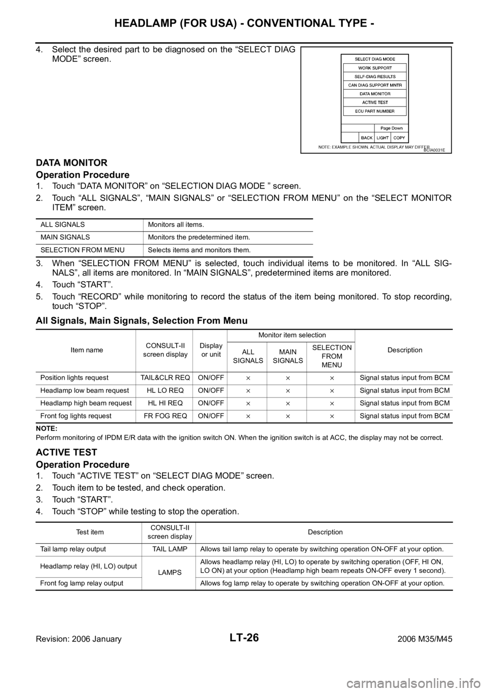
4. Select the desired part to be diagnosed on the “SELECT DIAG
MODE” screen.
DATA MONITOR
Operation Procedure
1. Touch “DATA MONITOR” on “SELECTION DIAG MODE ” screen.
2. Touch “ALL SIGNALS”, “MAIN SIGNALS” or “SELECTION FROM MENU” on the “SELECT MONITOR
ITEM” screen.
3. When “SELECTION FROM MENU” is selected, touch individual items to be monitored. In “ALL SIG-
NALS”, all items are monitored. In “MAIN SIGNALS”, predetermined items are monitored.
4. Touch “START”.
5. Touch “RECORD” while monitoring to record the status of the item being monitored. To stop recording,
touch “STOP”.
All Signals, Main Signals, Selection From Menu
NOTE:
Perform monitoring of IPDM E/R data with the ignition switch ON. When the ignition switch is at ACC, the display may not be correct.
ACTIVE TEST
Operation Procedure
1. Touch “ACTIVE TEST” on “SELECT DIAG MODE” screen.
2. Touch item to be tested, and check operation.
3. Touch “START”.
4. Touch “STOP” while testing to stop the operation.
BCIA0031E
ALL SIGNALS Monitors all items.
MAIN SIGNALS Monitors the predetermined item.
SELECTION FROM MENU Selects items and monitors them.
Item nameCONSULT-II
screen displayDisplay
or unitMonitor item selection
Description
ALL
SIGNALSMAIN
SIGNALSSELECTION
FROM
MENU
Position lights request TAIL&CLR REQ ON/OFF
Signal status input from BCM
Headlamp low beam request HL LO REQ ON/OFF
Signal status input from BCM
Headlamp high beam request HL HI REQ ON/OFF
Signal status input from BCM
Front fog lights request FR FOG REQ ON/OFF
Signal status input from BCM
Test itemCONSULT-II
screen displayDescription
Tail lamp relay output TAIL LAMP Allows tail lamp relay to operate by switching operation ON-OFF at your option.
Headlamp relay (HI, LO) output
LAMPSAllows headlamp relay (HI, LO) to operate by switching operation (OFF, HI ON,
LO ON) at your option (Headlamp high beam repeats ON-OFF every 1 second).
Front fog lamp relay output Allows fog lamp relay to operate by switching operation ON-OFF at your option.
Page 4454 of 5621

HEADLAMP (FOR USA) - CONVENTIONAL TYPE -
LT-27
C
D
E
F
G
H
I
J
L
MA
B
LT
Revision: 2006 January2006 M35/M45
Headlamp High Beam Does Not Illuminate (Both Sides)NKS003OA
1. CHECK COMBINATION SWITCH INPUT SIGNAL
With CONSULT-II
1. Select “BCM” on CONSULT-II. Select “HEAD LAMP” on
“SELECT TEST ITEM” screen.
2. Select “DATA MONITOR” on “SELECT DIAG MODE” screen.
Make sure that “HI BEAM SW” turns ON-OFF linked with opera-
tion of lighting switch.
Without CONSULT-II
Refer to LT-240, "
Combination Switch Inspection" .
OK or NG
OK >> GO TO 2.
NG >> Check combination switch (lighting switch). Refer to LT- 2 4 0 , "
Combination Switch Inspection" .
2. HEADLAMP ACTIVE TEST
With CONSULT-II
1. Select “IPDM E/R” on CONSULT-II. Select “ACTIVE TEST” on
“SELECT DIAG MODE” screen.
2. Select “LAMPS” on “SELECT TEST ITEM” screen.
3. Touch “HI” screen.
4. Make sure headlamp high beam operation.
Without CONSULT-II
1. Start auto active test. Refer to PG-24, "
Auto Active Test" .
2. Make sure headlamp high beam operation.
OK or NG
OK >> GO TO 3.
NG >> GO TO 4.
3. CHECK IPDM E/R
1. Select “IPDM E/R” on CONSULT-II. Select “DATA MONITOR”
on “SELECT DIAG MODE” screen.
2. Make sure “HL LO REQ” and “HL HI REQ” turns ON when light-
ing switch is in HI position.
OK or NG
OK >> Replace IPDM E/R. Refer to PG-31, "Removal and
Installation of IPDM E/R" .
NG >> Replace BCM. Refer to BCS-17, "
Removal and Installa-
tion of BCM" . When lighting switch is
HIGH position: HI BEAM SW ON
PKIA7585E
Headlamp high beam should operate
(Headlamp high beam repeats ON–OFF every 1 second).
Headlamp high beam should operate.
SKIA5774E
When lighting switch is
HIGH position: HL LO REQ ON
: HL HI REQ ON
PKIA7638E
Page 4485 of 5621

LT-58
HEADLAMP (FOR USA) - XENON TYPE -
Revision: 2006 January2006 M35/M45
4. Touch “HEAD LAMP” on “SELECT TEST ITEM” screen.
DATA MONITOR
Operation Procedure
1. Touch “HEAD LAMP” on “SELECT TEST ITEM” screen.
2. Touch “DATA MONITOR” on “SELECT DIAG MODE” screen.
3. Touch either “ALL SIGNALS” or “SELECTION FROM MENU” on the “SELECT MONITOR ITEM” screen.
4. When “SELECTION FROM MENU” is selected, touch individual items to be monitored. When “ALL SIG-
NALS” is selected, all the items will be monitored.
5. Touch “START”.
6. Touch “RECORD” while monitoring, then the status of the monitored item can be recorded. To stop
recording, touch “STOP”.
Display Item List
PKIA5226E
ALL SIGNALS Monitors all the signals.
SELECTION FROM MENU Selects items and monitor them.
Monitor item Contents
IGN ON SW “ON/OFF” Displays “IGN position (ON)/OFF, ACC position (OFF)” judged from the ignition switch signal.
ACC ON SW “ON/OFF” Displays “ACC (ON)/OFF, Ignition OFF (OFF)” status judged from ignition switch signal.
KEY ON SW “ON/OFF”Displays “Intelligent Key inserted into key slot (ON)/Intelligent Key removed from key slot
(OFF)” status judged from the key switch signal.
TURN SIGNAL R “ON/OFF” Displays status (turn right: ON/others: OFF) as judged from lighting switch signal.
TURN SIGNAL L “ON/OFF” Displays status (turn left: ON/others: OFF) as judged from lighting switch signal.
HI BEAM SW “ON/OFF”Displays status (high beam switch: ON/others: OFF) of high beam switch judged from lighting
switch signal.
HEAD LAMP SW 1 “ON/OFF”Displays status (headlamp switch 1: ON/others: OFF) of headlamp switch 1 judged from light-
ing switch signal.
HEAD LAMP SW 2 “ON/OFF”Displays status (headlamp switch 2: ON/others: OFF) of headlamp switch 2 judged from light-
ing switch signal.
TAIL LAMP SW “ON/OFF”Displays status (lighting switch 1ST or 2ND position: ON/others: OFF) of lighting switch
judged from lighting switch signal.
AUTO LIGHT SW “ON/OFF”Displays status of the lighting switch as judged from the lighting switch signal. (AUTO position:
ON/other than AUTO position: OFF)
PASSING SW “ON/OFF”Displays status (flash-to-passing switch: ON/others: OFF) of flash-to-passing switch judged
from lighting switch signal.
FR FOG SW “ON/OFF”Displays status (front fog lamp switch: ON/others: OFF) of front fog lamp switch judged from
lighting switch signal.
DOOR SW - DR “ON/OFF”Displays status of the driver door as judged from the driver door switch signal. (door is open:
ON/door is closed: OFF)
DOOR SW - AS “ON/OFF”Displays status of the passenger door as judged from the passenger door switch signal. (door
is open: ON/door is closed: OFF)
DOOR SW - RR “ON/OFF”Displays status of the rear door as judged from the rear door switch (RH) signal. (door is
open: ON/door is closed: OFF)