2006 INFINITI M35 ECO mode
[x] Cancel search: ECO modePage 5547 of 5621
WT-22
TROUBLE DIAGNOSES
Revision: 2006 January2006 M35/M45
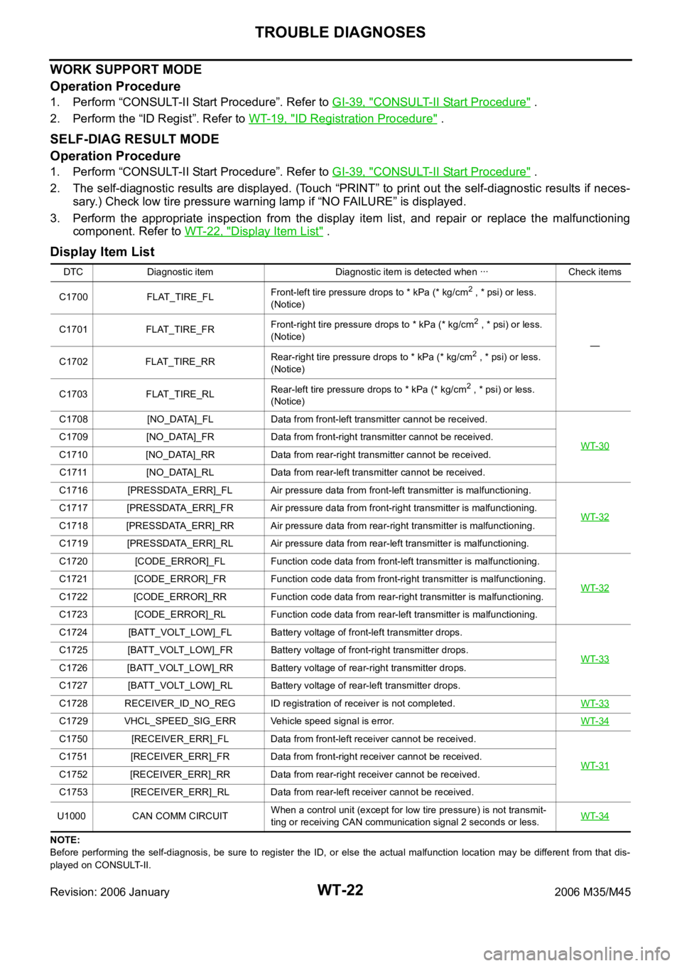
WORK SUPPORT MODE
Operation Procedure
1. Perform “CONSULT-II Start Procedure”. Refer to GI-39, "CONSULT-II Start Procedure" .
2. Perform the “ID Regist”. Refer to WT-19, "
ID Registration Procedure" .
SELF-DIAG RESULT MODE
Operation Procedure
1. Perform “CONSULT-II Start Procedure”. Refer to GI-39, "CONSULT-II Start Procedure" .
2. The self-diagnostic results are displayed. (Touch “PRINT” to print out the self-diagnostic results if neces-
sary.) Check low tire pressure warning lamp if “NO FAILURE” is displayed.
3. Perform the appropriate inspection from the display item list, and repair or replace the malfunctioning
component. Refer to WT-22, "
Display Item List" .
Display Item List
NOTE:
Before performing the self-diagnosis, be sure to register the ID, or else the actual malfunction location may be different from that dis-
played on CONSULT-II.DTC Diagnostic item Diagnostic item is detected when ꞏꞏꞏ Check items
C1700 FLAT_TIRE_FLFront-left tire pressure drops to * kPa (* kg/cm
2 , * psi) or less.
(Notice)
— C1701 FLAT_TIRE_FRFront-right tire pressure drops to * kPa (* kg/cm
2 , * psi) or less.
(Notice)
C1702 FLAT_TIRE_RRRear-right tire pressure drops to * kPa (* kg/cm
2 , * psi) or less.
(Notice)
C1703 FLAT_TIRE_RLRear-left tire pressure drops to * kPa (* kg/cm
2 , * psi) or less.
(Notice)
C1708 [NO_DATA]_FL Data from front-left transmitter cannot be received.
WT-30
C1709 [NO_DATA]_FR Data from front-right transmitter cannot be received.
C1710 [NO_DATA]_RR Data from rear-right transmitter cannot be received.
C1711 [NO_DATA]_RL Data from rear-left transmitter cannot be received.
C1716 [PRESSDATA_ERR]_FL Air pressure data from front-left transmitter is malfunctioning.
WT-32
C1717 [PRESSDATA_ERR]_FR Air pressure data from front-right transmitter is malfunctioning.
C1718 [PRESSDATA_ERR]_RR Air pressure data from rear-right transmitter is malfunctioning.
C1719 [PRESSDATA_ERR]_RL Air pressure data from rear-left transmitter is malfunctioning.
C1720 [CODE_ERROR]_FL Function code data from front-left transmitter is malfunctioning.
WT-32
C1721 [CODE_ERROR]_FR Function code data from front-right transmitter is malfunctioning.
C1722 [CODE_ERROR]_RR Function code data from rear-right transmitter is malfunctioning.
C1723 [CODE_ERROR]_RL Function code data from rear-left transmitter is malfunctioning.
C1724 [BATT_VOLT_LOW]_FL Battery voltage of front-left transmitter drops.
WT-33
C1725 [BATT_VOLT_LOW]_FR Battery voltage of front-right transmitter drops.
C1726 [BATT_VOLT_LOW]_RR Battery voltage of rear-right transmitter drops.
C1727 [BATT_VOLT_LOW]_RL Battery voltage of rear-left transmitter drops.
C1728 RECEIVER_ID_NO_REG ID registration of receiver is not completed.WT-33
C1729 VHCL_SPEED_SIG_ERR Vehicle speed signal is error.WT-34
C1750 [RECEIVER_ERR]_FL Data from front-left receiver cannot be received.
WT-31
C1751 [RECEIVER_ERR]_FR Data from front-right receiver cannot be received.
C1752 [RECEIVER_ERR]_RR Data from rear-right receiver cannot be received.
C1753 [RECEIVER_ERR]_RL Data from rear-left receiver cannot be received.
U1000 CAN COMM CIRCUITWhen a control unit (except for low tire pressure) is not transmit-
ting or receiving CAN communication signal 2 seconds or less. WT-34
Page 5549 of 5621
WT-24
TROUBLE DIAGNOSES
Revision: 2006 January2006 M35/M45
LOW TIRE PRESSURE WARNING CONTROL UNIT PART NUMBER
Operation Procedure
1. Perform “CONSULT-II Start Procedure”. Refer to GI-39, "CONSULT-II Start Procedure" .
2. The part number described on low tire pressure warning control unit sticker is displayed.
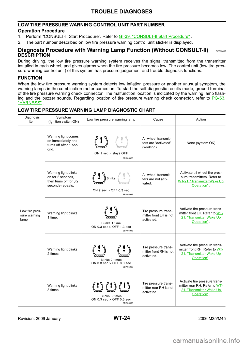
Diagnosis Procedure with Warning Lamp Function (Without CONSULT-II)NES000K6
DESCRIPTION
During driving, the low tire pressure warning system receives the signal transmitted from the transmitter
installed in each wheel, and gives alarms when the tire pressure becomes low. The control unit (low tire pres-
sure warning control unit) of this system has pressure judgement and trouble diagnosis functions.
FUNCTION
When the low tire pressure warning system detects low inflation pressure or another unusual symptom, the
warning lamps in the combination meter comes on. To start the self-diagnostic results mode, ground terminal
of the tire pressure warning check connector. The malfunction location is indicated by the warning lamp flash-
ing and the buzzer sounds. Regarding location of tire pressure warning check connector, refer to PG-63,
"HARNESS" .
LOW TIRE PRESSURE WARNING LAMP DIAGNOSTIC CHART
Diagnosis
ItemSymptom
(Ignition switch ON)Low tire pressure warning lamp Cause Action
Low tire pres-
sure warning
lampWarning light comes
on immediately and
turns off after 1 sec-
ond.All wheel transmit-
ters are “activated”
(working).None (system OK)
Warning light blinks
on for 2 seconds,
then turns off for 0.2
seconds-repeats.All wheel transmit-
ters are not acti-
vated.Activate all wheel tire pres-
sure transmitters. Refer to
WT-21, "
Transmitter Wake Up
Operation" .
Warning light blinks
1 time.Tire pressure trans-
mitter front LH is not
activated.Activate tire pressure trans-
mitter front LH. Refer to WT-
21, "Transmitter Wake Up
Operation" .
Warning light blinks
2 times.Tire pressure trans-
mitter front RH is not
activated.Activate tire pressure trans-
mitter front RH. Refer to WT-
21, "Transmitter Wake Up
Operation" .
Warning light blinks
3 times.Tire pressure trans-
mitter rear RH is not
activated.Activate tire pressure trans-
mitter rear RH. Refer to WT-
21, "Transmitter Wake Up
Operation" .
SEIA0592E
SEIA0593E
SEIA0594E
SEIA0595E
SEIA0596E
Page 5559 of 5621
WT-34
TROUBLE DIAGNOSIS FOR SELF-DIAGNOSTIC ITEMS
Revision: 2006 January2006 M35/M45
2. REPLACE TIRE PRESSURE TRANSMITTER
1. Check low tire pressure warning condition again, and replace malfunctioning tire pressure transmitter.
2. Perform ID registration of all transmitter.
Can ID registration of all tire pressure transmitters be completed?
YES >> GO TO 3.
NO >> GO TO the inspection 1. Refer to WT-30, "
Inspection 1: Transmitter no Data" .
3. VEHICLE DRIVING
Drive at a speed of 40 km/h (25 MPH) or more for 3 minutes, and then drive the vehicle at any speed for 10
minutes. Then check all tire pressures with CONSULT-II “DATA MONITOR” within 5 minutes.
Does
“DATA MONITOR” display tire pressure as normal without any warning lamp?
YES >> INSPECTION END
NO >> Replace malfunctioning transmitter, and perform “Step 3” again.
Inspection 7: Vehicle Speed SignalNES000KG
MALFUNCTION CODE NO. 52
1. CHECK SELF-DIAGNOSIS RESULTS
1. Turn ignition switch OFF.
2. Connect CONSULT-II and CONSULT-II CONVERTER to data link connector.
3. Turn ignition switch ON.
4. Touch “START (NISSAN BASED VHCL)” “AIR PRESSURE MONITOR”.
–If “AIR PRESSURE MONITOR” is not displayed, print the “SELECT SYSTEM” screen. Then refer to LAN-
7, "Precautions When Using CONSULT-II" .
NOTE:
Just after starting engine, or turning ignition switch ON, it may not be displayed even if “START (NISSAN
BASED VHCL)” is touched. In this case, reconnect CONSULT-II and CONSULT-II CONVERTER.
5. Touch “SELF-DIAG RESULTS” on “SELECT DIAG MODE” screen.
6. Check display contents in self-diagnostic results.
Is
“CAN COMM CIRCUIT” displayed in the self-diagnosis display items?
YES >> Malfunction in CAN communication system. GO TO LAN-7, "Precautions When Using CONSULT-
II" .
NO >> No malfunction. Check combination meter refer to DI-18, "
Trouble Diagnosis" .
Inspection 8: CAN Communication System MalfunctionNES000KS
1. CHECK LOW TIRE PRESSURE WARNING CONTROL UNIT CONNECTOR
1. Turn ignition switch OFF, disconnect low tire pressure warning control unit harness connector, and check
terminal for deformation, disconnection, looseness, etc.
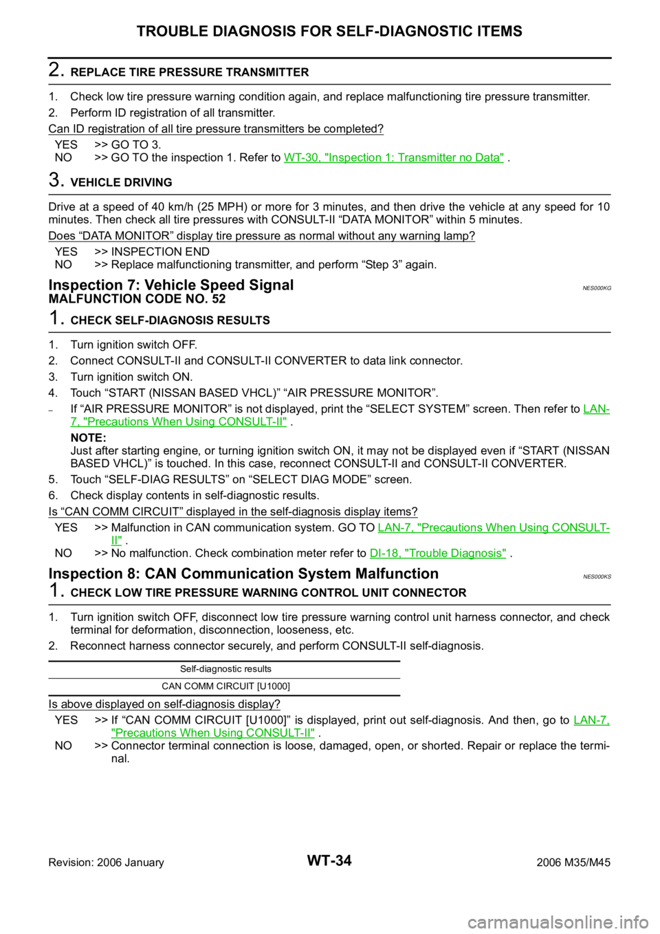
2. Reconnect harness connector securely, and perform CONSULT-II self-diagnosis.
Is above displayed on self-diagnosis display?
YES >> If “CAN COMM CIRCUIT [U1000]” is displayed, print out self-diagnosis. And then, go to LAN-7,
"Precautions When Using CONSULT-II" .
NO >> Connector terminal connection is loose, damaged, open, or shorted. Repair or replace the termi-
nal.
Self-diagnostic results
CAN COMM CIRCUIT [U1000]
Page 5591 of 5621

WW-24
FRONT WIPER AND WASHER SYSTEM
Revision: 2006 January2006 M35/M45
4. Touch “WIPER”.
WORK SUPPORT
Operation Procedure
1. Touch “WIPER” on “SELECT TEST ITEM” screen.
2. Touch “WORK SUPPORT” on “SELECT DIAG MODE” screen.
3. Touch “WIPER SPEED SETTING” on “SELECT WORK ITEM” screen.
4. Touch “START”.
5. Touch “CHANGE SETT”.
6. The setting will be changed and“ CURRENT SETTING” will be displayed.
7. Touch “END”.
Work Support Setting Item
NOTE:
Factory setting
DATA MONITOR
Operation Procedure
1. Touch “WIPER” on the “SELECT TEST ITEM” screen.
2. Touch “DATA MONITOR” on “SELECT DIAG MODE” screen.
3. Touch either “ALL SIGNALS” or “SELECTION FROM MENU” on “SELECT MONITOR ITEM” screen.
4. When “SELECTION FROM MENU” is selected, touch items to be monitored. If “ALL SIGNALS” is
selected, all items will be monitored.
5. Touch “START”.
6. Touch “RECORDING START” while monitoring to record the status of the item being monitored. To stop
recording, touch “RECORDING STOP”.
SKIB4803E
Item Description CONSULT-II
WIPER SPEED SETTINGWhen wiper switch is at INTERMITTENT, front wiper intermittent time can be selected
according to vehicle speed.
ONNOTE (Operated)/OFF (Not operated)ON/OFF
ALL SIGNALS Monitors all the signals.
SELECTION FROM MENU Selects items and monitors them.
Page 5594 of 5621
FRONT WIPER AND WASHER SYSTEM
WW-27
C
D
E
F
G
H
I
J
L
MA
B
WW
Revision: 2006 January2006 M35/M45
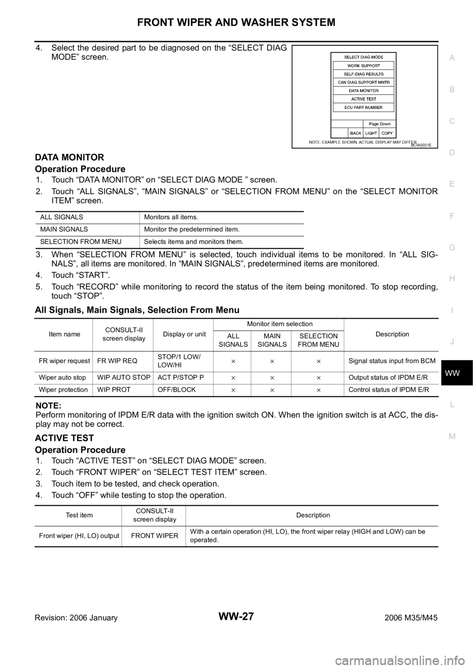
4. Select the desired part to be diagnosed on the “SELECT DIAG
MODE” screen.
DATA MONITOR
Operation Procedure
1. Touch “DATA MONITOR” on “SELECT DIAG MODE ” screen.
2. Touch “ALL SIGNALS”, “MAIN SIGNALS” or “SELECTION FROM MENU” on the “SELECT MONITOR
ITEM” screen.
3. When “SELECTION FROM MENU” is selected, touch individual items to be monitored. In “ALL SIG-
NALS”, all items are monitored. In “MAIN SIGNALS”, predetermined items are monitored.
4. Touch “START”.
5. Touch “RECORD” while monitoring to record the status of the item being monitored. To stop recording,
touch “STOP”.
All Signals, Main Signals, Selection From Menu
NOTE:
Perform monitoring of IPDM E/R data with the ignition switch ON. When the ignition switch is at ACC, the dis-
play may not be correct.
ACTIVE TEST
Operation Procedure
1. Touch “ACTIVE TEST” on “SELECT DIAG MODE” screen.
2. Touch “FRONT WIPER” on “SELECT TEST ITEM” screen.
3. Touch item to be tested, and check operation.
4. Touch “OFF” while testing to stop the operation.
BCIA0031E
ALL SIGNALS Monitors all items.
MAIN SIGNALS Monitor the predetermined item.
SELECTION FROM MENU Selects items and monitors them.
Item nameCONSULT-II
screen displayDisplay or unitMonitor item selection
Description
ALL
SIGNALSMAIN
SIGNALSSELECTION
FROM MENU
FR wiper request FR WIP REQSTOP/1 LOW/
LOW/HI
Signal status input from BCM
Wiper auto stop WIP AUTO STOP ACT P/STOP P
Output status of IPDM E/R
Wiper protection WIP PROT OFF/BLOCK
Control status of IPDM E/R
Te s t i t e mCONSULT-II
screen displayDescription
Front wiper (HI, LO) output FRONT WIPERWith a certain operation (HI, LO), the front wiper relay (HIGH and LOW) can be
operated.
Page 5598 of 5621
FRONT WIPER AND WASHER SYSTEM
WW-31
C
D
E
F
G
H
I
J
L
MA
B
WW
Revision: 2006 January2006 M35/M45
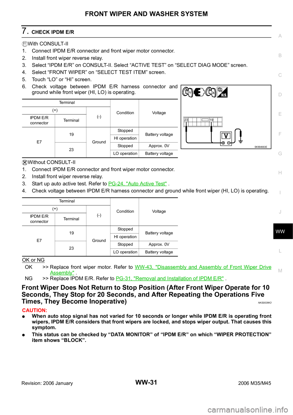
7. CHECK IPDM E/R
With CONSULT-II
1. Connect IPDM E/R connector and front wiper motor connector.
2. Install front wiper reverse relay.
3. Select “IPDM E/R” on CONSULT-II. Select “ACTIVE TEST” on “SELECT DIAG MODE” screen.
4. Select “FRONT WIPER” on “SELECT TEST ITEM” screen.
5. Touch “LO” or “HI” screen.
6. Check voltage between IPDM E/R harness connector and
ground while front wiper (HI, LO) is operating.
Without CONSULT-II
1. Connect IPDM E/R connector and front wiper motor connector.
2. Install front wiper reverse relay.
3. Start up auto active test. Refer to PG-24, "
Auto Active Test" .
4. Check voltage between IPDM E/R harness connector and ground while front wiper (HI, LO) is operating.
OK or NG
OK >> Replace front wiper motor. Refer to WW-43, "Disassembly and Assembly of Front Wiper Drive
Assembly" .
NG >> Replace IPDM E/R. Refer to PG-31, "
Removal and Installation of IPDM E/R" .
Front Wiper Does Not Return to Stop Position (After Front Wiper Operate for 10
Seconds, They Stop for 20 Seconds, and After Repeating the Operations Five
Times, They Become Inoperative)
NKS003WO
CAUTION:
When auto stop signal has not varied for 10 seconds or longer while IPDM E/R is operating front
wipers, IPDM E/R considers that front wipers are locked, and stops wiper output. That causes this
symptom.
This status can be checked by “DATA MONITOR” of “IPDM E/R” on which “WIPER PROTECTION”
item shows “BLOCK”.
Terminal
Condition Voltage (+)
(-)
IPDM E/R
connectorTerminal
E719
GroundStopped
Battery voltage
HI operation
23Stopped Approx. 0V
LO operation Battery voltage
Terminal
Condition Voltage (+)
(-)
IPDM E/R
connectorTerminal
E719
GroundStopped
Battery voltage
HI operation
23Stopped Approx. 0V
LO operation Battery voltage
SKIB4663E