Page 1127 of 5621

BL-188
INTELLIGENT KEY SYSTEM/ENGINE START FUNCTION
Revision: 2006 January2006 M35/M45
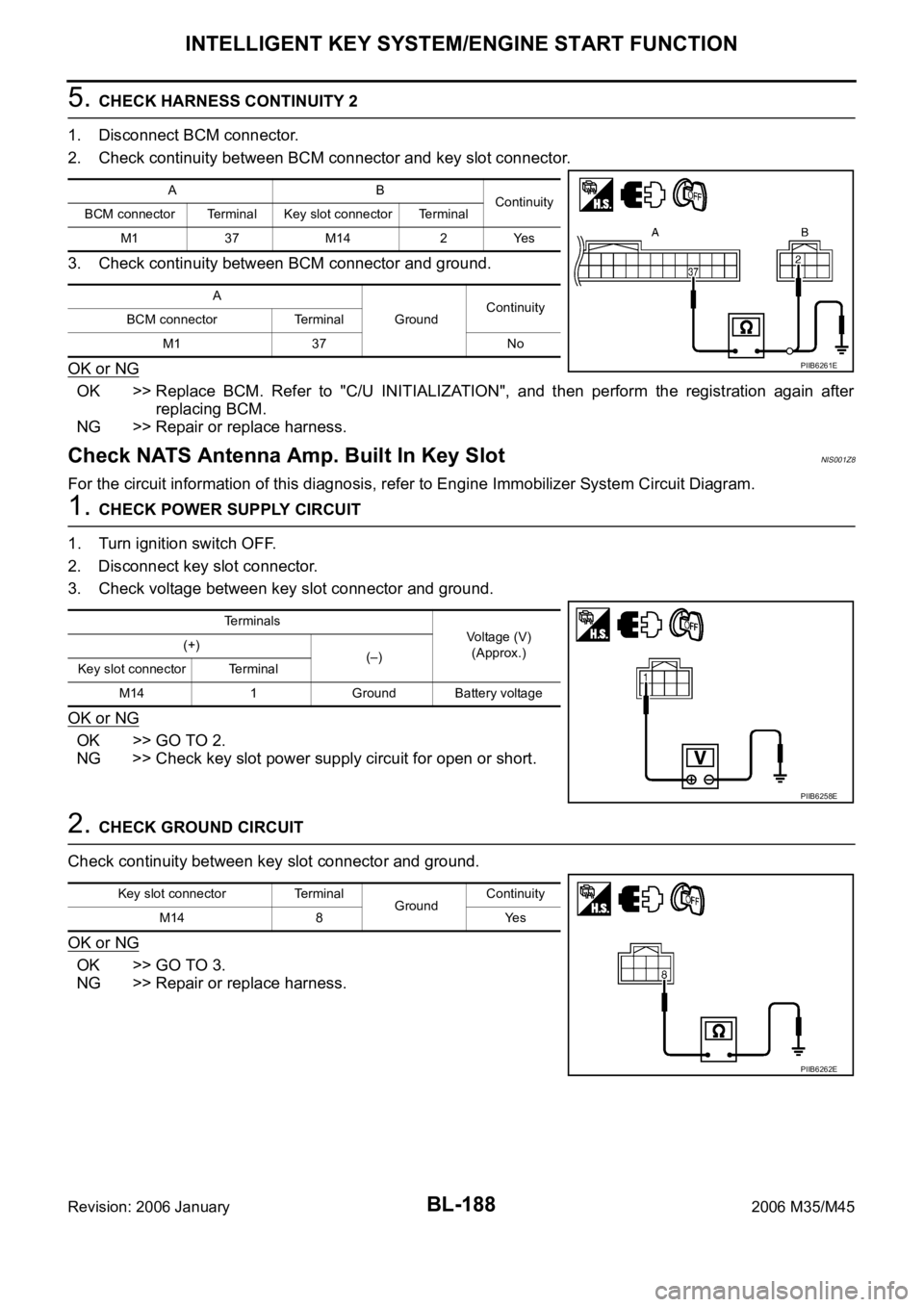
5. CHECK HARNESS CONTINUITY 2
1. Disconnect BCM connector.
2. Check continuity between BCM connector and key slot connector.
3. Check continuity between BCM connector and ground.
OK or NG
OK >> Replace BCM. Refer to "C/U INITIALIZATION", and then perform the registration again after
replacing BCM.
NG >> Repair or replace harness.
Check NATS Antenna Amp. Built In Key SlotNIS001Z8
For the circuit information of this diagnosis, refer to Engine Immobilizer System Circuit Diagram.
1. CHECK POWER SUPPLY CIRCUIT
1. Turn ignition switch OFF.
2. Disconnect key slot connector.
3. Check voltage between key slot connector and ground.
OK or NG
OK >> GO TO 2.
NG >> Check key slot power supply circuit for open or short.
2. CHECK GROUND CIRCUIT
Check continuity between key slot connector and ground.
OK or NG
OK >> GO TO 3.
NG >> Repair or replace harness.
AB
Continuity
BCM connector Terminal Key slot connector Terminal
M1 37 M14 2 Yes
A
GroundContinuity
BCM connector Terminal
M1 37 No
PIIB6261E
Terminals
Voltage (V)
(Approx.) (+)
(–)
Key slot connector Terminal
M14 1 Ground Battery voltage
PIIB6258E
Key slot connector Terminal
GroundContinuity
M14 8 Yes
PIIB6262E
Page 1128 of 5621
INTELLIGENT KEY SYSTEM/ENGINE START FUNCTION
BL-189
C
D
E
F
G
H
J
K
L
MA
B
BL
Revision: 2006 January2006 M35/M45
3. CHECK KEY SLOT SIGNAL
1. Connect key slot connector.
2. Check voltage between key slot connector and ground.
OK or NG
OK >> Check the condition of harness and connector.
NG >> Repair or replace harness between BCM and key slot.
Terminals
ConditionVoltage (V)
(Approx.) (+)
(–)
Key slot
connectorTerminal
M146
GroundCheck the voltage just
after the Intelligent Key
is inserted into the key
slot and the ignition
switch is turned to
START.The pointer of
the analog
tester fluctu-
ates. 7
PIIB6263E
Page 1153 of 5621
BL-214
TRUNK LID OPENER
Revision: 2006 January2006 M35/M45
CONSULT-II Function (BCM)NIS001ZR
CONSULT-II can display each diagnostic item using the diagnostic test modes shown following.
CONSULT-II INSPECTION PROCEDURE
CAUTION:
If CONSULT-II is used with no connection of CONSULT-II CONVERTER, malfunctions might be
detected in self-diagnosis depending on control unit which carry out CAN communication.
1. Turn ignition switch “OFF”.
2. Connect “CONSULT-II” and CONSULT-II CONVERTER to data
link connector (1).
3. Turn ignition switch “ON”.
4. Touch “START(NISSAN BASED VHCL)”.
5. Touch “BCM”.
If “BCM” is not indicated, go to GI-40, "
CONSULT-II Data Link
Connector (DLC) Circuit" .
BCM diagnosis
partInspection item, self-diagnosis
modeContent
TRUNKDATA MONITOR Displays the input data of BCM in real time basis.
ACTIVE TEST Give a drive signals to load to check the operation check.
PBIB2712E
BCIA0029E
BCIA0030E
Page 1154 of 5621
TRUNK LID OPENER
BL-215
C
D
E
F
G
H
J
K
L
MA
B
BL
Revision: 2006 January2006 M35/M45
6. Touch “TRUNK”.
7. Select diagnosis mode.
“DATA MONITOR” and “ACTIVE TEST” are available
DATA MONITOR
ACTIVE TEST
PIIA9936E
BCIA0031E
Monitored Item Description
IGN ON SW Indicates [ON/OFF] condition of ignition switch in ON position.
KEY ON SW Indicates [ON/OFF] condition of Intelligent Key inserted in key slot.
I KEY TRUNK/HAT Indicates [ON/OFF] condition of trunk lid open signal from Intelligent Key.
TRUNK OPNR SW Indicates [ON/OFF] condition of trunk lid opener switch.
VEHICLE SPEED This item displays vehicle speed.
Test item Content
TRUNK/GLASS HATCHThis test is able to check trunk lid opener actuator open operation. This actuator openes when “ON” on
CONSULT-II screen is touched.
Page 1156 of 5621

TRUNK LID OPENER
BL-217
C
D
E
F
G
H
J
K
L
MA
B
BL
Revision: 2006 January2006 M35/M45
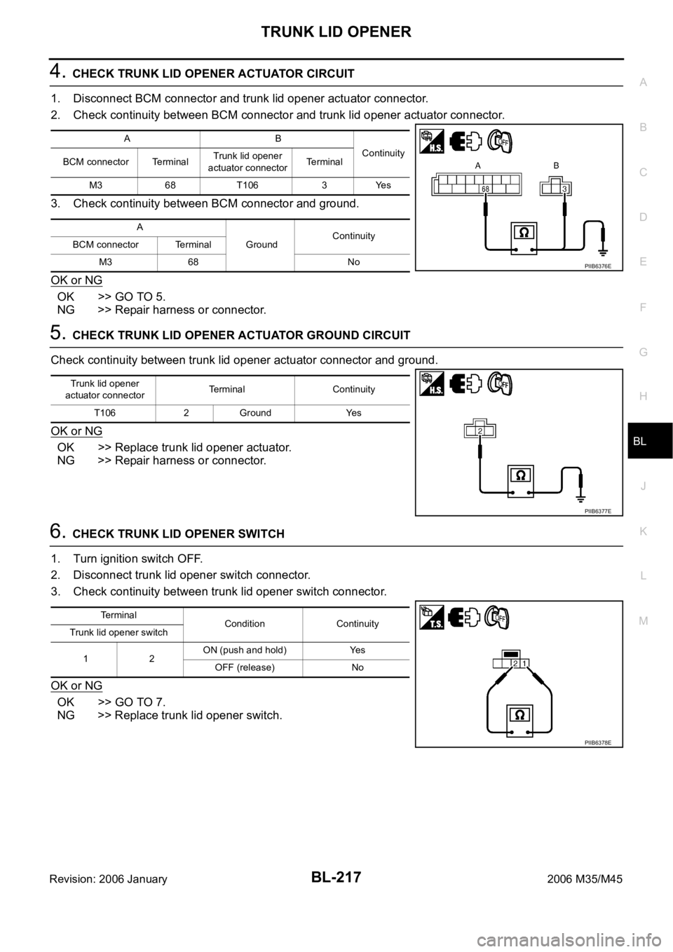
4. CHECK TRUNK LID OPENER ACTUATOR CIRCUIT
1. Disconnect BCM connector and trunk lid opener actuator connector.
2. Check continuity between BCM connector and trunk lid opener actuator connector.
3. Check continuity between BCM connector and ground.
OK or NG
OK >> GO TO 5.
NG >> Repair harness or connector.
5. CHECK TRUNK LID OPENER ACTUATOR GROUND CIRCUIT
Check continuity between trunk lid opener actuator connector and ground.
OK or NG
OK >> Replace trunk lid opener actuator.
NG >> Repair harness or connector.
6. CHECK TRUNK LID OPENER SWITCH
1. Turn ignition switch OFF.
2. Disconnect trunk lid opener switch connector.
3. Check continuity between trunk lid opener switch connector.
OK or NG
OK >> GO TO 7.
NG >> Replace trunk lid opener switch.
AB
Continuity
BCM connector TerminalTrunk lid opener
actuator connectorTerminal
M3 68 T106 3 Yes
A
GroundContinuity
BCM connector Terminal
M3 68 No
PIIB6376E
Trunk lid opener
actuator connectorTerminal Continuity
T106 2 Ground Yes
PIIB6377E
Te r m i n a l
Condition Continuity
Trunk lid opener switch
12ON (push and hold) Yes
OFF (release) No
PIIB6378E
Page 1161 of 5621

BL-222
VEHICLE SECURITY (THEFT WARNING) SYSTEM
Revision: 2006 January2006 M35/M45
System DescriptionNIS001ZU
DESCRIPTION
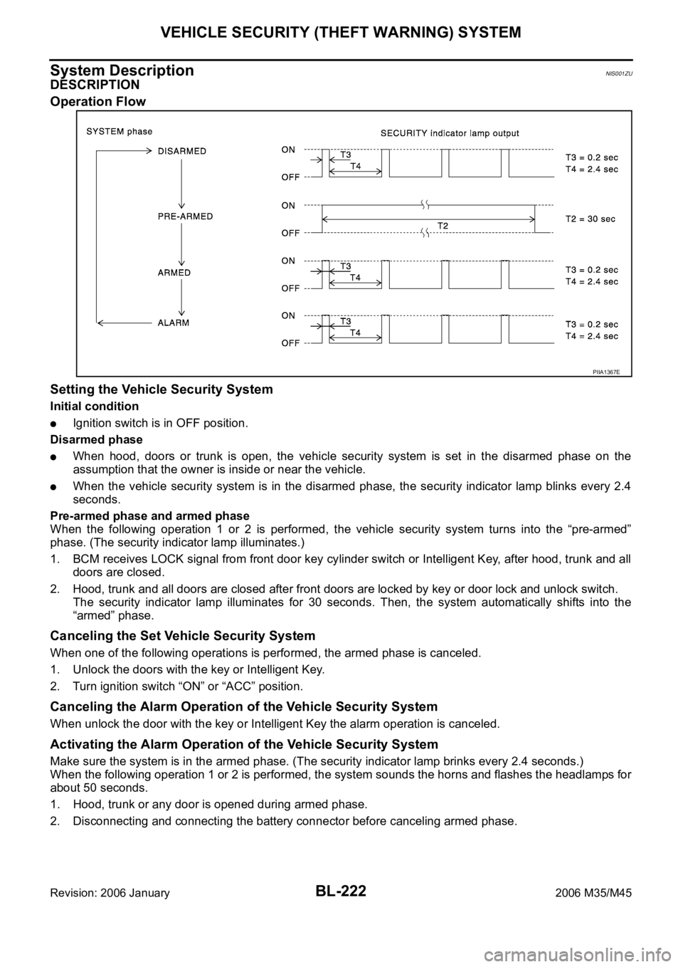
Operation Flow
Setting the Vehicle Security System
Initial condition
Ignition switch is in OFF position.
Disarmed phase
When hood, doors or trunk is open, the vehicle security system is set in the disarmed phase on the
assumption that the owner is inside or near the vehicle.
When the vehicle security system is in the disarmed phase, the security indicator lamp blinks every 2.4
seconds.
Pre-armed phase and armed phase
When the following operation 1 or 2 is performed, the vehicle security system turns into the “pre-armed”
phase. (The security indicator lamp illuminates.)
1. BCM receives LOCK signal from front door key cylinder switch or Intelligent Key, after hood, trunk and all
doors are closed.
2. Hood, trunk and all doors are closed after front doors are locked by key or door lock and unlock switch.
The security indicator lamp illuminates for 30 seconds. Then, the system automatically shifts into the
“armed” phase.
Canceling the Set Vehicle Security System
When one of the following operations is performed, the armed phase is canceled.
1. Unlock the doors with the key or Intelligent Key.
2. Turn ignition switch “ON” or “ACC” position.
Canceling the Alarm Operation of the Vehicle Security System
When unlock the door with the key or Intelligent Key the alarm operation is canceled.
Activating the Alarm Operation of the Vehicle Security System
Make sure the system is in the armed phase. (The security indicator lamp brinks every 2.4 seconds.)
When the following operation 1 or 2 is performed, the system sounds the horns and flashes the headlamps for
about 50 seconds.
1. Hood, trunk or any door is opened during armed phase.
2. Disconnecting and connecting the battery connector before canceling armed phase.
PIIA1367E
Page 1162 of 5621

VEHICLE SECURITY (THEFT WARNING) SYSTEM
BL-223
C
D
E
F
G
H
J
K
L
MA
B
BL
Revision: 2006 January2006 M35/M45
POWER SUPPLY AND GROUND CIRCUIT
Power is supplied at all times
through 50A fusible link (letter F , located in the fuse and fusible link box)
to BCM terminal 55,
through 10A fuse [No. 21, located in the fuse block (J/B)]
to BCM terminal 42,
through 10A fuse [No. 71, located in the IPDM E/R]
to IPDM E/R internal CPU,
through 15A fuse [No. 78, located in the IPDM E/R]
to IPDM E/R internal CPU,
through 15A fuse [No. 37, located in the fuse block (J/B)]
to multi-function switch (security indicator) terminal 1.
With the ignition switch in the ACC or ON position, power is supplied
through 10A fuse [No. 6, located in the fuse block (J/B)]
to BCM terminal 11.
Ground is supplied
to BCM terminal 52
through body grounds M16 and M70.
INITIAL CONDITION TO ACTIVATE THE SYSTEM
The operation of the vehicle security system is controlled by the doors, hood and trunk.
To activate the vehicle security system, BCM must receive signals indicating the doors, hood and trunk are
closed and the doors are locked by key fob.
When a door is open, terminal 12 (passenger side door), 13 (rear RH door), 62 (driver side door), 63 (rear LH
door) receives a ground signal from each door switch.
When front door LH is unlocked by power window main switch (door lock and unlock switch), BCM terminal 22
receives an unlock signal from terminal 14 of power window main switch with power window serial link.
When front door RH is unlocked by power window sub-switch (passenger side) (door lock and unlock switch),
BCM terminal 22 receives an unlock signal from terminal 16 of power window sub-switch (passenger side)
with power window serial link.
When front door key cylinder switch is in LOCK position, ground is supplied
to power window main switch terminal 4
through front door key cylinder switch terminals 6 and 4
through body grounds M16 and M70.
When the hood is open, IPDM E/R receives a ground signal
to IPDM E/R terminal 60
through hood switch terminal 2
through hood switch terminal 1
through body grounds E22, and E43.
The IPDM E/R then sends a signal to BCM via CAN communication line.
When the trunk is open, ground is supplied
to BCM terminal 57
through trunk room lamp switch terminal 1
through trunk room lamp switch terminal 2
through body grounds B5, B40 and B131.
Page 1171 of 5621

BL-232
VEHICLE SECURITY (THEFT WARNING) SYSTEM
Revision: 2006 January2006 M35/M45
Terminals and Reference Value of BCMNIS001ZZ
Terminals and Reference Value of IPDM E/RNIS00200
Terminal Wire color Item ConditionVoltage [V]
(Approx.)
11 V Power supply (ACC) Ignition switch (ACC or ON position) Battery voltage
12 PFront door switch
passenger side signalON (Open)
OFF (Closed) 0 Battery voltage
13 O/L Rear door switch RH signal ON (Open)
OFF (Closed) 0 Battery voltage
22 G Power window serial linkIgnition switch ON or power window
timer operating
23 W/V Security indicator lamp Goes off
Illuminates Battery voltage 0
37 LG Key switch signalKey inserted in key slot
key
removed from key slotBattery voltage 0
39 L CAN-H — —
40 P CAN-L — —
42 P Power source (fuse) — Battery voltage
52 B Ground — 0
55 W Battery power supply (fusible link) — Battery voltage
56 W Trunk lid key cylinder switch Neutral
Unlock Battery voltage 0
57 SB Trunk room lamp switch signal ON (Open)
OFF (Closed) 0 Battery voltage
62 VFront door switch
driver side signalON (Open)
OFF (Closed) 0 Battery voltage
63 R/G Rear door switch LH signal ON (Open)
OFF (Closed) 0 Battery voltage
PIIA2344J
Terminal Wire color Item ConditionVoltage [V]
(Approx.)
38 B Ground (power) — 0
48 G/B Horn relay control signalPanic alarm is operating 0
Other than above Battery voltage
49 L CAN-H — —
50 P CAN-L — —
51 B Ground (signal) — 0
60 LG/B Hood switch signal ON (Open)
OFF (closed) 0 Battery voltage