2006 INFINITI M35 ignition
[x] Cancel search: ignitionPage 1206 of 5621

IVIS (INFINITI VEHICLE IMMOBILIZER SYSTEM-NATS)
BL-267
C
D
E
F
G
H
J
K
L
MA
B
BL
Revision: 2006 January2006 M35/M45
Terminals and Reference Value for IPDM E/RNIS0020L
Terminals and Reference Value for PDUNIS0020M
38 WIgnition power supply
(ON or START)ONPower supply position is in ON posi-
tionBattery voltage
39 L CAN H — — —
40 P CAN L — — —
42 P Power source (fuse) — — Battery voltage
52 B Ground — — 0
55 WPower source (Fusible
link)— — Battery voltage Te r m i -
nal
No.Wire
colorItemCondition
Voltage (V)
(Approx.) Push-but-
ton igni-
tion
switch
positionOperation or conditions
Te r -
minal
No.Wire
ColorItemCondition
Voltage (V)
(Approx.) Push-
button
ignition
switch
positionOperation or conditions
4W/RStarter motor power
supplyLOCK — 0
START Starter motor is activating Battery voltage
49 L CAN H — — —
50 P CAN L — — —
53 GR/RA/T Shift position
signalONA/T shift position is P/ N posi-
tionBattery voltage
LOCK Other than above 0
Te r -
minal
No.Wire
colorItemCondition
Voltage (V)
(Approx.) Push-
button
ignition
switch
positionOperation or conditions
1 P Wake up signalLOCKSleep condition (30 seconds or more
after all doors are closed under the con-
dition that the power supply position is in
the LOCK position)Battery voltage
— Wake-up condition (Open driver door) 0
2 G Starter control signalON At starter motor cranking 0
— Any condition other than above Battery voltage
3GRSteering lock unit
power sourceLOCKPush-button ignition switch is pressed
under the condition that Intelligent Key is
in the vehicle or Intelligent Key is inserted0
Battery voltage 0
— Any condition other than above 0
Page 1207 of 5621

BL-268
IVIS (INFINITI VEHICLE IMMOBILIZER SYSTEM-NATS)
Revision: 2006 January2006 M35/M45
CONSULT-IINIS0020N
CONSULT-II INSPECTION PROCEDURE
1. Turn ignition switch OFF.
2. Insert IVIS (NATS) program card into CONSULT-II.
3. Connect CONSULT-II and CONSULT-II CONVERTER to data
link connector (1).
6VSteering lock control
signal-1—Push-button ignition switch is pressed
under the condition that Intelligent Key is
in the vehicle or Intelligent Key is insertedBattery voltage
LOCKPower supply position is in LOCK posi-
tion
(Steering lock activated)Battery voltage 0 Battery volt-
age
(Battery voltage is detected when
activating the steering lock)
7LGSteering lock control
signal-2—Push-button ignition switch is pressed
under the condition that Intelligent Key is
in the vehicle or Intelligent Key is insertedBattery voltage
LOCKPower supply position is in LOCK posi-
tion
(Steering lock activated)Battery voltage
0 Battery volt-
age
(Battery voltage is detected when
activating the steering lock)
9OSteering lock feed
back signal—Power supply position is in ACC or ON
position0
LOCKPower supply position is in LOCK posi-
tion0
8 0
(0V is detected when activating the
steering lock)
10 B Ground — — 0
11 YIPDM E/R current sig-
nalSTART At starter motor cranking 5
LOCK Any condition other than above 2
12 R Feed back signalLOCKSleep condition (30 seconds or more
after all doors are closed under the con-
dition that the power supply position is in
the LOCK position)1
—Wake-up condition (any condition other
than above)0
13 R Starter relaySTART At starter motor cranking Battery voltage
— Any condition other than above 4
14 SB Power source (fuse) — — Battery voltage
15 LPower source (fusible
link)— — Battery voltage
17 GPower source (fusible
link)— — Battery voltage Te r -
minal
No.Wire
colorItemCondition
Voltage (V)
(Approx.) Push-
button
ignition
switch
positionOperation or conditions
Program card : NATS (AEN04D)
PBIB2712E
Page 1208 of 5621

IVIS (INFINITI VEHICLE IMMOBILIZER SYSTEM-NATS)
BL-269
C
D
E
F
G
H
J
K
L
MA
B
BL
Revision: 2006 January2006 M35/M45
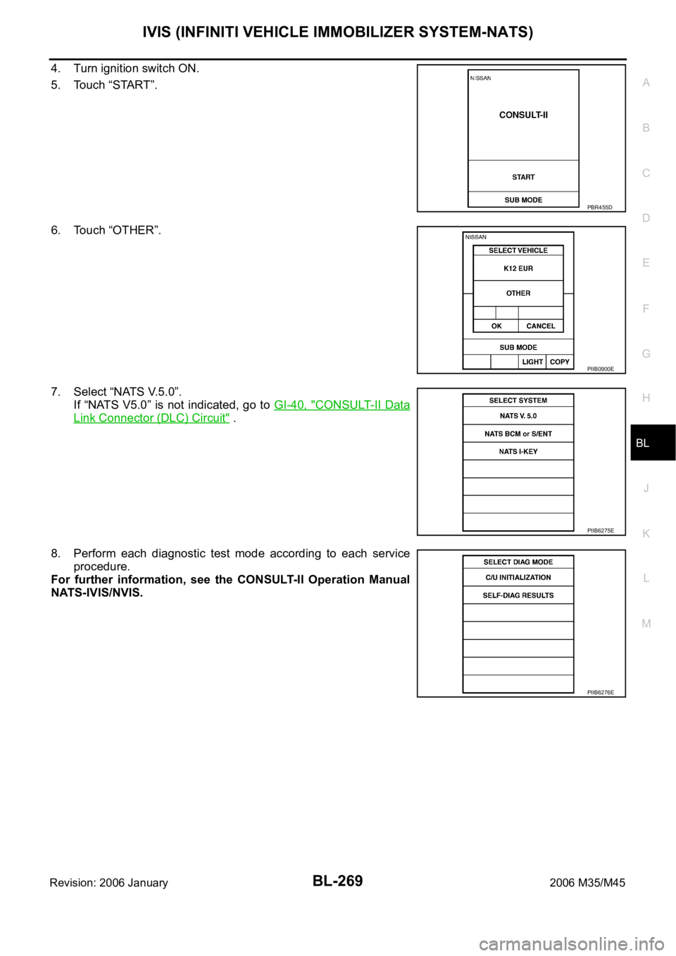
4. Turn ignition switch ON.
5. Touch “START”.
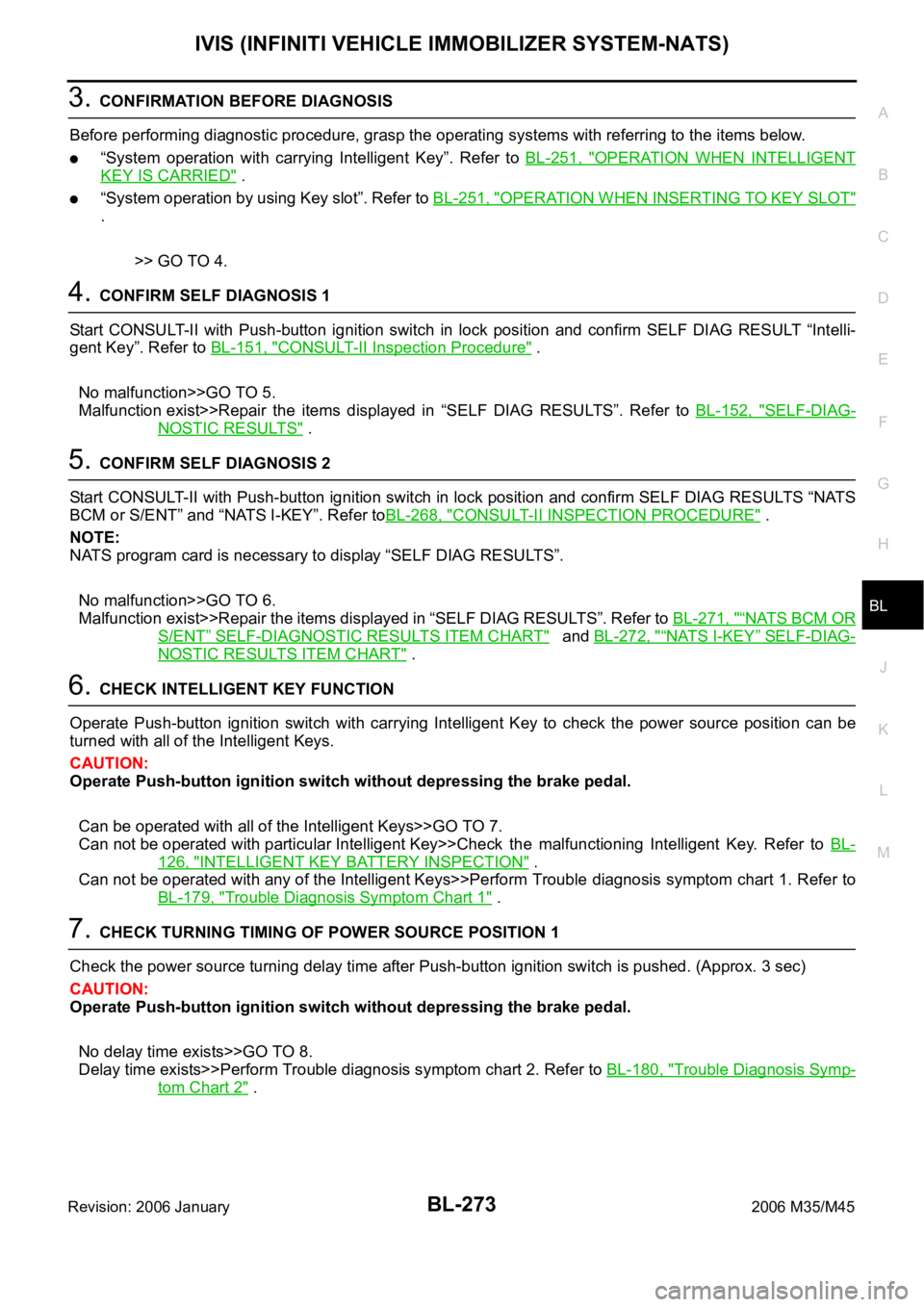
6. Touch “OTHER”.
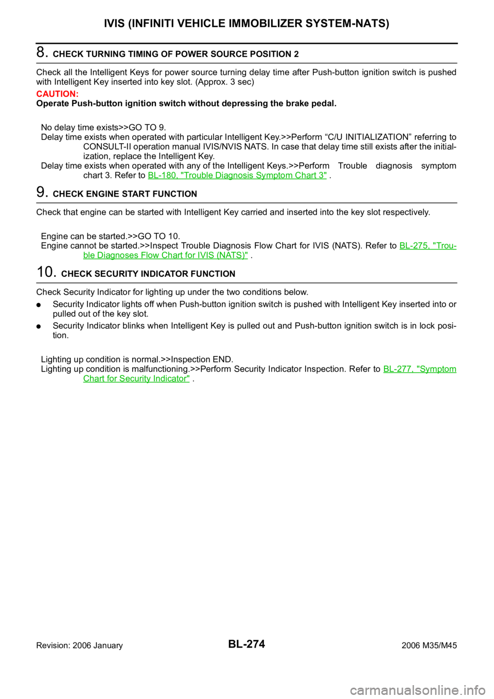
7. Select “NATS V.5.0”.
If “NATS V5.0” is not indicated, go to GI-40, "
CONSULT-II Data
Link Connector (DLC) Circuit" .
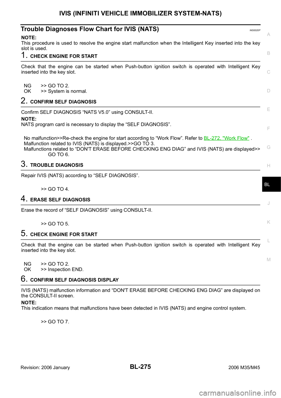
8. Perform each diagnostic test mode according to each service
procedure.
For further information, see the CONSULT-II Operation Manual
NATS-IVIS/NVIS.
PBR455D
PIIB0900E
PIIB6275E
PIIB6276E
Page 1209 of 5621

BL-270
IVIS (INFINITI VEHICLE IMMOBILIZER SYSTEM-NATS)
Revision: 2006 January2006 M35/M45
CONSULT-II DIAGNOSTIC TEST MODE FUNCTION
NOTE:
When any initialization is performed, all ID previously registered will be erased and all NATS ignition keys
must be registered again.
The engine cannot be started with an unregistered key. In this case, the system will show “DIFFERENCE
OF KEY” or “LOCK MODE” as a self-diagnostic result on the CONSULT-II screen.
In rare case, “CHAIN OF ECM-IMMU” might be stored as a self-diagnostic result during key registration
procedure, even if the system is not malfunctioning.
HOW TO READ SELF-DIAGNOSTIC RESULTS
System Diagnosis mode DescriptionReference
page
NATS V5.0C/U INTIALIZATIONPerform registration again after repair, part replacement, and
additional key ID registration.
CAUTION:
“Control Unit Initialization” is activated only after per-
forming “Release steering lock”.Refer to the
Technical Bul-
letin.
SELF-DIAG RESULTS
Malfunctioning system stored in the ECM is displayed.
Printing the contents
Erasing the error recordBL-271
NATS BCM or S/ENTPIN READThe specified numbers of each control unit for acquisition of
password for control unit initialization are displayedRefer to the
Technical Bul-
letin.
STEERING LOCK
RELEASEIf the engine switch cannot be operated (the steering lock
cannot be released), release the steering lock forcibly and
make the engine switch operation possible.
CAUTION:
Always perform “Control Unit Initialization” and “Immo-
bilizer ID Registration” after performing “Release Steer-
ing Lock”.Refer to the
Technical Bul-
letin.
SELF-DIAG RESULTS
Malfunctioning system stored in the BCM is displayed.
Printing the contents
Erasing the error recordBL-271
NATS I-KEY SELF-DIAG RESULTS
Malfunctioning system stored in the Intelligent Key unit is
displayed.
Printing the contents
Erasing the error recordBL-272
PIIB6280E
Page 1210 of 5621

IVIS (INFINITI VEHICLE IMMOBILIZER SYSTEM-NATS)
BL-271
C
D
E
F
G
H
J
K
L
MA
B
BL
Revision: 2006 January2006 M35/M45
“NATS V5.0” SELF-DIAGNOSTIC RESULTS ITEM CHART
“NATS BCM OR S/ENT” SELF-DIAGNOSTIC RESULTS ITEM CHART
Suspect Systems Description Possible malfunction Action to take/Reference page
NO DTC NO DTC — —
DON'T ERASE BEFORE
CHECKING ENG DIAGThere is the engine trouble
diagnosis information in ECM
(ECM trouble diagnosis is nec-
essary separately)Engine control system malfunc-
tionThere is the engine trouble
diagnosis information in ECM.
Check the trouble diagnostic
results of “ENGINE” before
that.
LOCK MODE
[P1610]The immobilizer switches to the
mode that prevents the engine
from being started. If the ID ver-
ification between BCM and
ECM is NG, the ID verification
malfunction between remote
control starter and BCM may be
detected 5 times or more.—When “LOCK MODE” is dis-
played, check for any other dis-
played malfunction, and then
erase the self-diagnostic results
after replacement.
ID DISCORD, IMM-ECM
[P1611]The ID verification results
between BCM and ECM are
NG. The registration is neces-
sary.Registration of ECM is not com-
pletedBL-280
ECM malfunction Replace ECM.
CHAIN OF ECM-IMMU
[P1612]Inactive communication
between ECM and BCMOpen circuit in battery power
supply line of BCM
BL-278
Open circuit in ignition power
supply line of BCM
Open circuit in ground of BCM
Short circuit in communication
line between BCM and ECM to
power supply line
Open circuit in communication
line between BCM and ECM
Short circuit in communication
line between BCM and ECM to
ground
ECM malfunction
BCM malfunction
CHAIN OF IMMU-KEY
[P1614]BCM malfunction BCM malfunctionBCS-17
Suspect Systems Description Possible malfunction Action to take/Reference page
NO DTC NO DTC — —
ID DISCORD BCM-ECM
[B2192]The ID verification results
between BCM and ECM are
NG. The registration is neces-
sary.Registration of ECM is not com-
pletedPerform “Control Unit Initializa-
tion”, and then perform the ID
registration. Refer to the Tech-
nical Bulletin.
ECM malfunction Replace ECM.
CHAIN OF BCM-ECM
[B2193]Inactive communication
between ECM and BCMShort circuit in communication
line between BCM and ECM to
power supply lineMalfunction have occurred in
CAN communication
Check “Self-diagnostic Results”
of “Intelligent Key” using CON-
SULT-II. Refer to BL-152,
"SELF-DIAGNOSTIC
RESULTS" . Open circuit in communication
line between BCM and ECM
Short circuit in communication
line between BCM and ECM to
ground
ECM malfunction Replace ECM.
Page 1212 of 5621

IVIS (INFINITI VEHICLE IMMOBILIZER SYSTEM-NATS)
BL-273
C
D
E
F
G
H
J
K
L
MA
B
BL
Revision: 2006 January2006 M35/M45
3. CONFIRMATION BEFORE DIAGNOSIS
Before performing diagnostic procedure, grasp the operating systems with referring to the items below.
“System operation with carrying Intelligent Key”. Refer to BL-251, "OPERATION WHEN INTELLIGENT
KEY IS CARRIED" .
“System operation by using Key slot”. Refer to BL-251, "OPERATION WHEN INSERTING TO KEY SLOT"
.
>> GO TO 4.
4. CONFIRM SELF DIAGNOSIS 1
Start CONSULT-II with Push-button ignition switch in lock position and confirm SELF DIAG RESULT “Intelli-
gent Key”. Refer to BL-151, "
CONSULT-II Inspection Procedure" .
No malfunction>>GO TO 5.
Malfunction exist>>Repair the items displayed in “SELF DIAG RESULTS”. Refer to BL-152, "
SELF-DIAG-
NOSTIC RESULTS" .
5. CONFIRM SELF DIAGNOSIS 2
Start CONSULT-II with Push-button ignition switch in lock position and confirm SELF DIAG RESULTS “NATS
BCM or S/ENT” and “NATS I-KEY”. Refer toBL-268, "
CONSULT-II INSPECTION PROCEDURE" .
NOTE:
NATS program card is necessary to display “SELF DIAG RESULTS”.
No malfunction>>GO TO 6.
Malfunction exist>>Repair the items displayed in “SELF DIAG RESULTS”. Refer to BL-271, "
“NATS BCM OR
S/ENT” SELF-DIAGNOSTIC RESULTS ITEM CHART" and BL-272, "“NATS I-KEY” SELF-DIAG-
NOSTIC RESULTS ITEM CHART" .
6. CHECK INTELLIGENT KEY FUNCTION
Operate Push-button ignition switch with carrying Intelligent Key to check the power source position can be
turned with all of the Intelligent Keys.
CAUTION:
Operate Push-button ignition switch without depressing the brake pedal.
Can be operated with all of the Intelligent Keys>>GO TO 7.
Can not be operated with particular Intelligent Key>>Check the malfunctioning Intelligent Key. Refer to BL-
126, "INTELLIGENT KEY BATTERY INSPECTION" .
Can not be operated with any of the Intelligent Keys>>Perform Trouble diagnosis symptom chart 1. Refer to
BL-179, "
Trouble Diagnosis Symptom Chart 1" .
7. CHECK TURNING TIMING OF POWER SOURCE POSITION 1
Check the power source turning delay time after Push-button ignition switch is pushed. (Approx. 3 sec)
CAUTION:
Operate Push-button ignition switch without depressing the brake pedal.
No delay time exists>>GO TO 8.
Delay time exists>>Perform Trouble diagnosis symptom chart 2. Refer to BL-180, "
Trouble Diagnosis Symp-
tom Chart 2" .
Page 1213 of 5621

BL-274
IVIS (INFINITI VEHICLE IMMOBILIZER SYSTEM-NATS)
Revision: 2006 January2006 M35/M45
8. CHECK TURNING TIMING OF POWER SOURCE POSITION 2
Check all the Intelligent Keys for power source turning delay time after Push-button ignition switch is pushed
with Intelligent Key inserted into key slot. (Approx. 3 sec)
CAUTION:
Operate Push-button ignition switch without depressing the brake pedal.
No delay time exists>>GO TO 9.
Delay time exists when operated with particular Intelligent Key.>>Perform “C/U INITIALIZATION” referring to
CONSULT-II operation manual IVIS/NVIS NATS. In case that delay time still exists after the initial-
ization, replace the Intelligent Key.
Delay time exists when operated with any of the Intelligent Keys.>>Perform Trouble diagnosis symptom
chart 3. Refer to BL-180, "
Trouble Diagnosis Symptom Chart 3" .
9. CHECK ENGINE START FUNCTION
Check that engine can be started with Intelligent Key carried and inserted into the key slot respectively.
Engine can be started.>>GO TO 10.
Engine cannot be started.>>Inspect Trouble Diagnosis Flow Chart for IVIS (NATS). Refer to BL-275, "
Trou-
ble Diagnoses Flow Chart for IVIS (NATS)" .
10. CHECK SECURITY INDICATOR FUNCTION
Check Security Indicator for lighting up under the two conditions below.
Security Indicator lights off when Push-button ignition switch is pushed with Intelligent Key inserted into or
pulled out of the key slot.
Security Indicator blinks when Intelligent Key is pulled out and Push-button ignition switch is in lock posi-
tion.
Lighting up condition is normal.>>Inspection END.
Lighting up condition is malfunctioning.>>Perform Security Indicator Inspection. Refer to BL-277, "
Symptom
Chart for Security Indicator" .
Page 1214 of 5621

IVIS (INFINITI VEHICLE IMMOBILIZER SYSTEM-NATS)
BL-275
C
D
E
F
G
H
J
K
L
MA
B
BL
Revision: 2006 January2006 M35/M45
Trouble Diagnoses Flow Chart for IVIS (NATS)NIS0020P
NOTE:
This procedure is used to resolve the engine start malfunction when the Intelligent Key inserted into the key
slot is used.
1. CHECK ENGINE FOR START
Check that the engine can be started when Push-button ignition switch is operated with Intelligent Key
inserted into the key slot.
NG >> GO TO 2.
OK >> System is normal.
2. CONFIRM SELF DIAGNOSIS
Confirm SELF DIAGNOSIS “NATS V5.0” using CONSULT-II.
NOTE:
NATS program card is necessary to display the “SELF DIAGNOSIS”.
No malfunction>>Re-check the engine for start according to “Work Flow”. Refer to BL-272, "
Work Flow" .
Malfunction related to IVIS (NATS) is displayed.>>GO TO 3.
Malfunctions related to “DON'T ERASE BEFORE CHECKING ENG DIAG” and IVIS (NATS) are displayed>>
GO TO 6.
3. TROUBLE DIAGNOSIS
Repair IVIS (NATS) according to “SELF DIAGNOSIS”.
>> GO TO 4.
4. ERASE SELF DIAGNOSIS
Erase the record of “SELF DIAGNOSIS” using CONSULT-II.
>> GO TO 5.
5. CHECK ENGINE FOR START
Check that the engine can be started when Push-button ignition switch is operated with Intelligent Key
inserted into the key slot.
NG >> GO TO 2.
OK >> Inspection END.
6. CONFIRM SELF DIAGNOSIS DISPLAY
IVIS (NATS) malfunction information and “DON'T ERASE BEFORE CHECKING ENG DIAG” are displayed on
the CONSULT-II screen.
NOTE:
This indication means that malfunctions have been detected in IVIS (NATS) and engine control system.
>> GO TO 7.