2006 INFINITI M35 warning
[x] Cancel search: warningPage 5100 of 5621

SB-1
SEAT BELTS
H RESTRAINTS
CONTENTS
C
D
E
F
G
I
J
K
L
M
SECTION SB
A
B
SB
Revision: 2006 January2006 M35/M45
SEAT BELTS
PRECAUTIONS .......................................................... 2
Precautions for Supplemental Restraint System
(SRS) “AIR BAG” and “SEAT BELT PRE-TEN-
SIONER” .................................................................. 2
Precaution for Seat Belt Service .............................. 2
AFTER A COLLISION ........................................... 2
PRE-CRASH SEAT BELT .......................................... 3
Component Parts and Harness Connector Location ..... 3
System Description .................................................. 3
FUNCTION DESCRIPTION .................................. 4
FAIL-SAFE MODE ................................................ 4
CAN Communication System Description ................ 5
CAN Communication Unit ........................................ 5
Schematic ................................................................ 6
Wiring Diagram — PSB — ....................................... 7
Terminals and Reference Value for Pre-Crash Seat
Belt Control Unit ..................................................... 13
Work Flow .............................................................. 13
CONSULT-II Function (PRECRASH SEATBELT) ... 14
CONSULT-II INSPECTION PROCEDURE ......... 14
HOW TO READ SELF-DIAGNOSTIC RESULTS ... 15
SELF-DIAGNOSTIC RESULTS ITEM CHART ... 15
DATA MONITOR ITEM CHART .......................... 15
Preliminary Check .................................................. 16
PRE-CRASH SEAT BELT OPERATION
INSPECTION ...................................................... 16
Diagnoses Symptom Chart .................................... 16
Check CAN Communication System Inspection
[U1000] ................................................................... 16
Ignition Power Supply Circuit Check ...................... 17
Motor Power Supply and Ground Circuit Check
[B2454] ................................................................... 17
Seat Belt Buckle Switch (Driver Side) Circuit Check ... 19
Seat Belt Buckle Switch (Passenger Side) Circuit
Check ..................................................................... 21
Brake Pedal Stroke Sensor Circuit Check [B2453] ... 22
Pre-Crash Seat Belt Motor LH Circuit Check [B2452]
... 25
Pre-Crash Seat Belt Motor RH Circuit Check [B2451] ................................................................... 27
Brake Pedal Stroke Sensor Shield Wire Circuit
Check ..................................................................... 28
Removal and Installation of Pre-Crash Seat Belt
Control Unit ............................................................. 29
REMOVAL ........................................................
... 29
INSTALLATION ................................................... 29
SEAT BELTS ............................................................. 30
System Description ................................................. 30
SEAT BELT WARNING CHIME ........................... 30
SEAT BELT WARNING LAMP ............................. 30
Removal and Installation of Front Seat Belt ........... 30
REMOVAL OF SEAT BELT RETRACTOR .......... 30
INSTALLATION OF SEAT BELT RETRACTOR ... 31
REMOVAL OF SEAT BELT BUCKLE .................. 31
INSTALLATION OF SEAT BELT BUCKLE .......
... 31
Removal and Installation of Rear Seat Belt ............ 32
REMOVAL OF SEAT BELT RETRACTOR .......... 32
INSTALLATION OF SEAT BELT RETRACTOR ... 32
REMOVAL OF SEAT BELT BUCKLE .................. 32
INSTALLATION OF SEAT BELT BUCKLE .......... 33
Seat Belt Inspection ................................................ 33
AFTER A COLLISION ......................................... 33
PRELIMINARY CHECKS .................................... 33
SEAT BELT RETRACTOR ON-VEHICLE
CHECK ................................................................ 34
SEAT BELT RETRACTOR OFF-VEHICLE
CHECK (FRONT SEAT BELT) ............................ 35
SEAT BELT RETRACTOR OFF-VEHICLE
CHECK (REAR SEAT BELT) ............................... 35
LATCH (LOWER ANCHORS AND TETHER FOR
CHILDREN) SYSTEM ............................................... 36
Removal and Installation ........................................ 36
REMOVAL ........................................................
... 36
INSTALLATION ................................................... 36
TOP TETHER STRAP CHILD RESTRAINT ............. 37
Removal and Installation ........................................ 37
REMOVAL ........................................................
... 37
INSTALLATION ................................................... 37
Page 5103 of 5621
SB-4
PRE-CRASH SEAT BELT
Revision: 2006 January2006 M35/M45
FUNCTION DESCRIPTION
Operation condition
Pre-crash seat belt operates under the following conditions.
Operation prohibition condition
If operation condition is satisfied, pre-crash seat belt does not operate under the following conditions.
*1 :When pre-crash seat belt doesn't operate after it continuously operates 3 times or more, operation can be performed again by stop-
ping operation for approximately 7 minutes.
*
2 : Refer to SB-4, "FAIL-SAFE MODE" for details of fail-safe mode.
FAIL-SAFE MODE
When a malfunction occurs in the following system, the pre-crash seat belt function is controlled according to
the malfunctioning parts.
Also, seat belt warning lamp blinks with fastening driver seat belt when the following malfunction occurs.
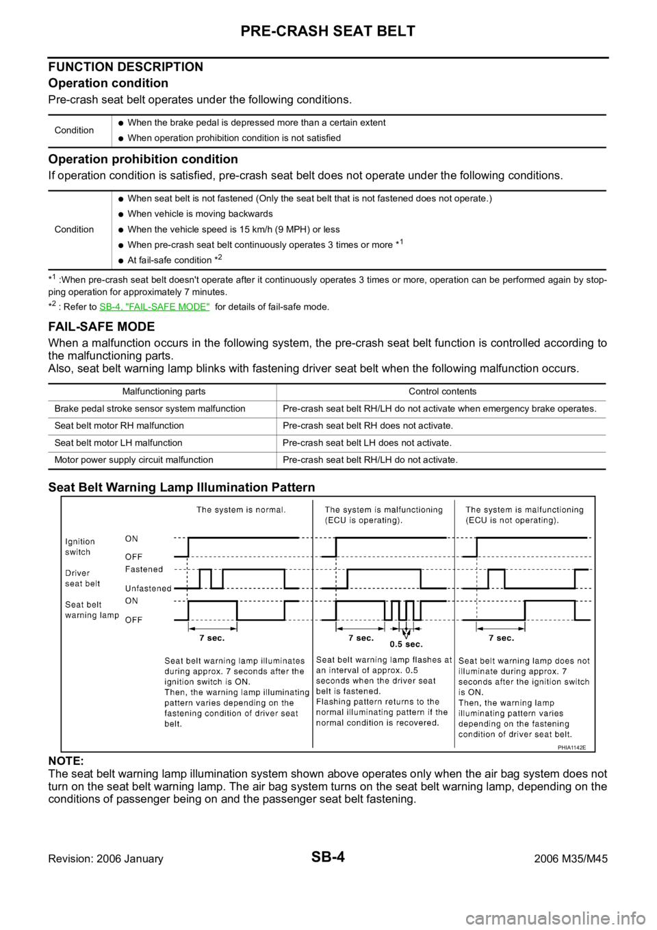
Seat Belt Warning Lamp Illumination Pattern
NOTE:
The seat belt warning lamp illumination system shown above operates only when the air bag system does not
turn on the seat belt warning lamp. The air bag system turns on the seat belt warning lamp, depending on the
conditions of passenger being on and the passenger seat belt fastening.
ConditionWhen the brake pedal is depressed more than a certain extent
When operation prohibition condition is not satisfied
Condition
When seat belt is not fastened (Only the seat belt that is not fastened does not operate.)
When vehicle is moving backwards
When the vehicle speed is 15 km/h (9 MPH) or less
When pre-crash seat belt continuously operates 3 times or more *1
At fail-safe condition *2
Malfunctioning parts Control contents
Brake pedal stroke sensor system malfunction Pre-crash seat belt RH/LH do not activate when emergency brake operates.
Seat belt motor RH malfunction Pre-crash seat belt RH does not activate.
Seat belt motor LH malfunction Pre-crash seat belt LH does not activate.
Motor power supply circuit malfunction Pre-crash seat belt RH/LH do not activate.
PHIA1142E
Page 5129 of 5621
SB-30
SEAT BELTS
Revision: 2006 January2006 M35/M45
SEAT BELTSPFP:86884
System DescriptionNHS0008I
SEAT BELT WARNING CHIME
With ignition switch turned ON and seat belt unfastened (seat belt switch ON), warning chime will sound
for approximately 6 seconds.
If warning chime does not sound, refer to DI-74, "Seat Belt Buckle Switch Signal Inspection" .
SEAT BELT WARNING LAMP
Fasten driver's seat belt.
The seat belt warning lamp should go out.
If the seat belt warning lamp does not go out, refer to DI-43, "Wiring Diagram — WARN —" .
Removal and Installation of Front Seat Belt NHS0008J
CAUTION:
Before servicing SRS, turn the ignition switch off, disconnect both battery cables and wait at least 3
minutes.
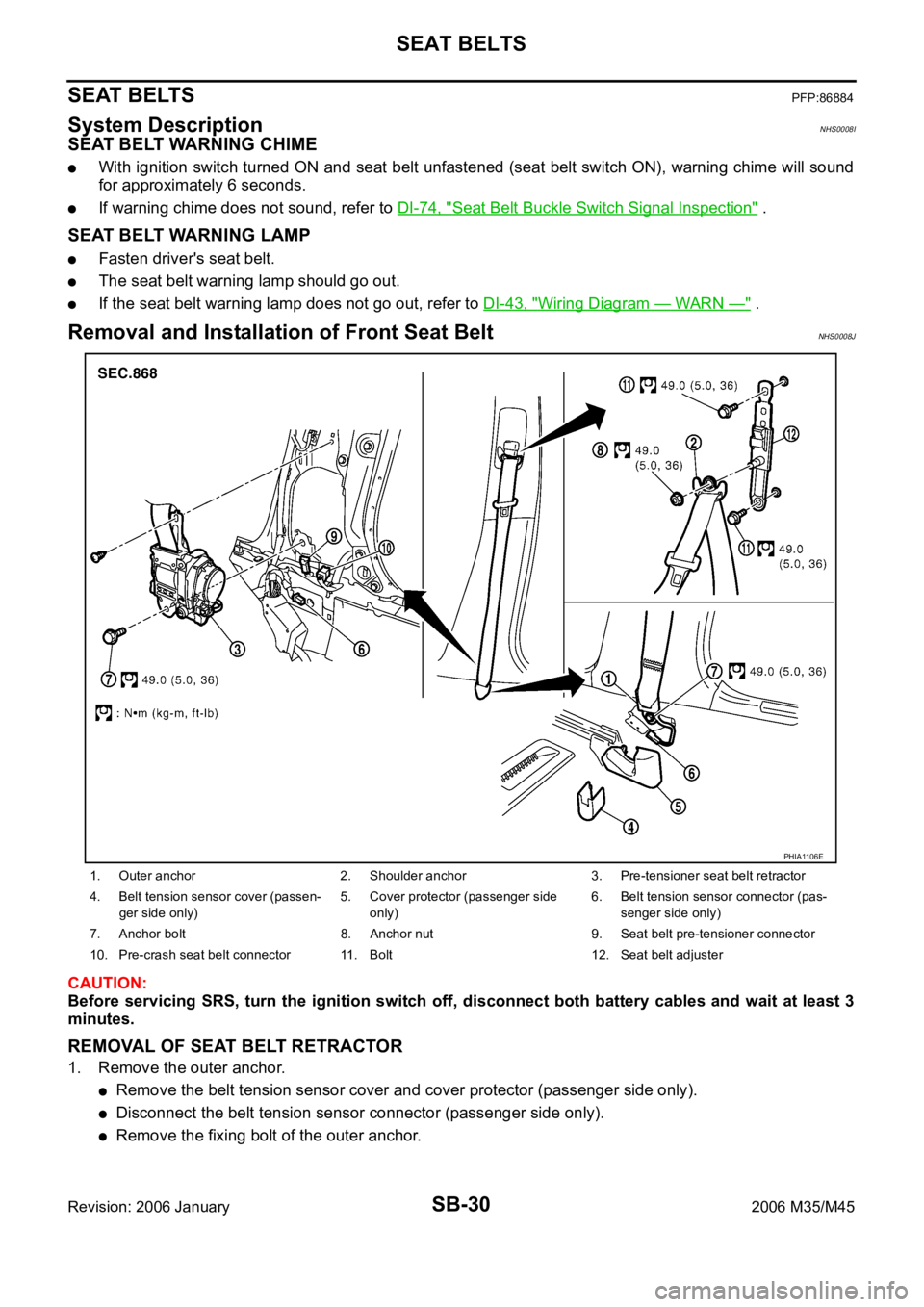
REMOVAL OF SEAT BELT RETRACTOR
1. Remove the outer anchor.
Remove the belt tension sensor cover and cover protector (passenger side only).
Disconnect the belt tension sensor connector (passenger side only).
Remove the fixing bolt of the outer anchor.
1. Outer anchor 2. Shoulder anchor 3. Pre-tensioner seat belt retractor
4. Belt tension sensor cover (passen-
ger side only)5. Cover protector (passenger side
only)6. Belt tension sensor connector (pas-
senger side only)
7. Anchor bolt 8. Anchor nut 9. Seat belt pre-tensioner connector
10. Pre-crash seat belt connector 11. Bolt 12. Seat belt adjuster
PHIA1106E
Page 5132 of 5621
SEAT BELTS
SB-33
C
D
E
F
G
I
J
K
L
MA
B
SB
Revision: 2006 January2006 M35/M45
INSTALLATION OF SEAT BELT BUCKLE
Install in the reverse order of removal.
Tighten by specified torque.
Seat Belt InspectionNHS0008L
AFTER A COLLISION
WAR NING :
Inspect all seat belt assemblies including retractors and attaching hardware after any collision.
NISSAN / INFINITI recommends that all seat belt assemblies in use during a collision be replaced
unless the collision was minor and the belts show no damage and continue to operate properly. Fail-
ure to do so could result in serious personal injury in an accident. Seat belt assemblies not in use dur-
ing a collision should also be replaced if either damage or improper operation is noted. Seat belt pre-
tensioned should be replaced even if the seat belts are not in use during a frontal collision in which
the air bags are deployed.
Replace any seat belt assembly (including anchor bolts) if:
The seat belt was in use at the time of a collision (except for minor collisions and the belts, retractors and
buckles show no damage and continue to operate properly).
The seat belt was damaged in an accident. (i.e. torn webbing, bent retractor or guide, etc.)
The seat belt attaching point was damaged in an accident. Inspect the seat belt attaching area for damage
or distortion and repair as necessary before installing a new seat belt assembly.
Anchor bolts are deformed or worn out.
The seat belt pre-tensioner should be replaced even if the seat belts are not in use during the collision in
which the air bags are deployed.
PRELIMINARY CHECKS
1. Check the seat belt warning lamp/chime for proper operation as follows:
a. Switch ignition ON. The seat belt warning lamp should illuminate. Also, the seat belt warning chime should
sound for about six seconds.
b. Fasten driver's seat belt. The seat belt warning lamp should go out and the chime (if sounding) should
stop.
2. If the air bag warning lamp is blinking, conduct self-diagnosis using CONSULT-II, and air bag warning
lamp. Refer to SRS-19, "
SRS Operation Check" .
3. Check that the seat belt retractor, seat belt anchor and buckle bolts are securely attached.
4. Check the shoulder seat belt guide and shoulder belt height adjuster for front seats. Ensure guide swivels
freely and that webbing lays flat and does not bind in guide. Ensure height adjuster operates properly and
holds securely.
5. Check retractor operation:
a. Fully extend the seat belt webbing and check for twists, tears or other damage.
b. Allow the seat belt to retract. Ensure that webbing returns smoothly and completely into the retractor. If
the seat belt does not return smoothly, wipe the inside of the loops with a clean paper cloth. Because dirt
built up in the loops of the upper anchors can cause the seat belts to retract slowly.
c. Fasten the seat belt. Check the seat belt returns smoothly and completely to the retractor. If the webbing
does not return smoothly, the cause may be an accumulation of dust or dirt. Use the “SEAT BELT TAPE
SET” and perform the following steps.
Inspect the front seat belt though-anchor
1. Pull the seat belt out to a length of 500 mm (19.69 in) or more.
2. Use a clip or other device to the fix the seat belt at the center pillar webbing opening.
3. Pass a thin wire though the though-anchor webbing opening. Hold both ends of the wire and pull it
tantly while moving it up and down several times along the webbing opening surface to move matter
stuck there.
4. Any dirt that can not be removed with the wire can be removed by cleaning the opening with a clean
cloth.
5. Apply tape at the point where the webbing contacts the though-anchor webbing opening. Tightening torque : 49.0 Nꞏm (5.0 kg-m, 36 ft-lb)
Page 5160 of 5621

CHARGING SYSTEM
SC-23
C
D
E
F
G
H
I
J
L
MA
B
SC
Revision: 2006 January2006 M35/M45
CHARGING SYSTEM PFP:00011
System Description NKS003NN
DESCRIPTION
The alternator provides DC voltage to operate the vehicle's electrical system and to keep the battery charged.
The voltage output is controlled by the IC regulator.
Power is supplied at all times
through 10A fuse [No. 36, located in the fuse, fusible link and relay block (J/B)]
to alternator terminal 4 (“S” terminal).
“B” terminal supplies power to charge the battery and operate the vehicle's electrical system. Output voltage is
controlled by the IC regulator at terminal 4 (“S” terminal) detecting the input voltage.
The alternator is grounded to the engine block.
With the ignition switch in the ON or START position, power is supplied
through 10A fuse [No. 14, located in the fuse block (J/B)]
to combination meter terminal 12 for the charge warning lamp.
Ground is supplied at signal
to combination meter terminal 22
through alternator terminal 3 (“L” terminal).
Then power and ground are supplied, the charge warning lamp will illuminate.
When the alternator is providing sufficient voltage with the engine running, the ground is opened and the
charge warning lamp will go off.
If the charge warning lamp illuminates with the engine running, a malfunction is indicated.
Ground is supplied
to alternator terminal 2 (“E” terminal)
through grounds E222, E223 and E224. (VQ35DE)
through ground E212. (VK45DE)
MALFUNCTION INDICATOR
The IC regulator warning function activates to illuminate the charge warning lamp, if any of the following symp-
toms occur while alternator is operating:
Excessive voltage is produced.
No voltage is produced.
Page 5170 of 5621
CHARGING SYSTEM
SC-33
C
D
E
F
G
H
I
J
L
MA
B
SC
Revision: 2006 January2006 M35/M45
2. CHECK “L” TERMINAL CIRCUIT (OPEN)
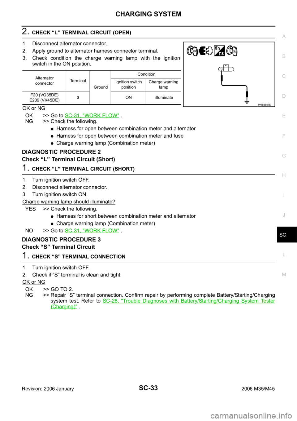
1. Disconnect alternator connector.
2. Apply ground to alternator harness connector terminal.
3. Check condition the charge warning lamp with the ignition
switch in the ON position.
OK or NG
OK >> Go to SC-31, "WORK FLOW" .
NG >> Check the following.
Harness for open between combination meter and alternator
Harness for open between combination meter and fuse
Charge warning lamp (Combination meter)
DIAGNOSTIC PROCEDURE 2
Check “L” Terminal Circuit (Short)
1. CHECK “L” TERMINAL CIRCUIT (SHORT)
1. Turn ignition switch OFF.
2. Disconnect alternator connector.
3. Turn ignition switch ON.
Charge warning lamp should illuminate?
YES >> Check the following.
Harness for short between combination meter and alternator
Charge warning lamp (Combination meter)
NO >> Go to SC-31, "
WORK FLOW" .
DIAGNOSTIC PROCEDURE 3
Check “S” Terminal Circuit
1. CHECK “S” TERMINAL CONNECTION
1. Turn ignition switch OFF.
2. Check if “S” terminal is clean and tight.
OK or NG
OK >> GO TO 2.
NG >> Repair “S” terminal connection. Confirm repair by performing complete Battery/Starting/Charging
system test. Refer to SC-28, "
Trouble Diagnoses with Battery/Starting/Charging System Tester
(Charging)" .
Alternator
connectorTerminal
GroundCondition
Ignition switch
positionCharge warning
lamp
F20 (VQ35DE)
E209 (VK45DE)3 ON illuminate
PKIB8807E
Page 5362 of 5621

SRS-1
SUPPLEMENTAL RESTRAINT SYSTEM (SRS)
H RESTRAINTS
CONTENTS
C
D
E
F
G
I
J
K
L
M
SECTION SRS
A
B
SRS
Revision: 2006 January2006 M35/M45
SUPPLEMENTAL RESTRAINT SYSTEM (SRS)
PRECAUTIONS .......................................................... 3
Precautions for Supplemental Restraint System
(SRS) “AIR BAG” and “SEAT BELT PRE-TEN-
SIONER” .................................................................. 3
Precautions for SRS “AIR BAG” and “SEAT BELT
PRE-TENSIONER” Service ..................................... 3
Occupant Classification System Precaution ............ 3
PREPARATION ........................................................... 4
Commercial Service Tools ........................................ 4
SUPPLEMENTAL RESTRAINT SYSTEM (SRS) ....... 5
SRS Configuration ..............................................
..... 5
Front Seat Belt Pre-Tensioner with Load Limiter ...... 6
Front Side Air Bag .................................................... 6
Side Curtain Air Bag ................................................. 6
Occupant Classification System (OCS) ................... 7
Passenger Air Bag Status Condition ........................ 7
Component Parts of Occupant Classification Sys-
tem ........................................................................... 7
TROUBLE DIAGNOSIS .............................................. 8
Trouble Diagnosis Introduction ................................. 8
DIAGNOSIS FUNCTION ....................................... 8
HOW TO PERFORM TROUBLE DIAGNOSIS
FOR QUICK AND ACCURATE REPAIR ............... 8
WORK FLOW ........................................................ 9
Component Parts Location ..................................... 10
Schematic ............................................................... 11
Wiring Diagram — SRS — ..................................... 12
CONSULT-II Function ............................................ 17
DIAGNOSIS MODE FOR CONSULT-II ............... 17
HOW TO CHANGE SELF-DIAGNOSIS MODE
WITH CONSULT-II .............................................. 17
HOW TO ERASE SELF-DIAGNOSTIC
RESULTS ............................................................ 18
Self-Diagnosis Function (Without CONSULT-II) ..... 18
HOW TO CHANGE SELF-DIAGNOSIS MODE
WITHOUT CONSULT-II ...................................... 18
HOW TO ERASE SELF-DIAGNOSTIC
RESULTS ............................................................ 18
SRS Operation Check ............................................ 19
DIAGNOSTIC PROCEDURE 1 ........................... 19Trouble Diagnosis with CONSULT-II ...................... 21
DIAGNOSTIC PROCEDURE 2 ........................... 21
DIAGNOSTIC PROCEDURE 3 ........................... 25
DIAGNOSTIC PROCEDURE 4 (CONTINUED
FROM DIAGNOSTIC PROCEDURE 2) .............. 27
DIAGNOSTIC PROCEDURE 5 ........................... 27
Trouble Diagnosis without CONSULT-II ................. 32
DIAGNOSTIC PROCEDURE 6 ........................... 32
WARNING LAMP FLASH CODE CHART ........... 32
Trouble Diagnosis: “AIR BAG” Warning Lamp Does
Not Turn OFF ......................................................... 36
DIAGNOSTIC PROCEDURE 7 ........................... 36
Trouble Diagnosis: “AIR BAG” Warning Lamp Does
Not Turn ON ........................................................... 37
DIAGNOSTIC PROCEDURE 8 ........................... 37
DRIVER AIR BAG MODULE .................................... 38
Removal and Installation ........................................ 38
REMOVAL ........................................................
... 38
INSTALLATION ................................................... 39
SPIRAL CABLE ........................................................ 40
Removal and Installation ........................................ 40
REMOVAL ........................................................
... 40
INSTALLATION ................................................... 40
FRONT PASSENGER AIR BAG MODULE .............. 42
Removal and Installation ........................................ 42
REMOVAL ........................................................
... 42
INSTALLATION ................................................... 42
SIDE CURTAIN AIR BAG MODULE ........................ 43
Removal and Installation ........................................ 43
REMOVAL ........................................................
... 43
INSTALLATION ................................................... 44
CRASH ZONE SENSOR ........................................... 45
Removal and Installation ........................................ 45
REMOVAL ........................................................
... 45
INSTALLATION ................................................... 45
SIDE AIR BAG (SATELLITE) SENSOR ................... 46
Removal and Installation ........................................ 46
REMOVAL ........................................................
... 46
INSTALLATION ................................................... 46
Page 5369 of 5621
SRS-8
TROUBLE DIAGNOSIS
Revision: 2006 January2006 M35/M45
TROUBLE DIAGNOSISPFP:00004
Trouble Diagnosis IntroductionNHS00090
CAUTION:
Do not use electrical test equipment on any circuit related to the SRS unless instructed in this Ser-
vice Manual. SRS wiring harnesses can be identified by yellow and/or orange harnesses or har-
ness connectors.
Do not repair, splice or modify the SRS wiring harness. If the harness is damaged, replace it with a
new one.
Keep ground portion clean.
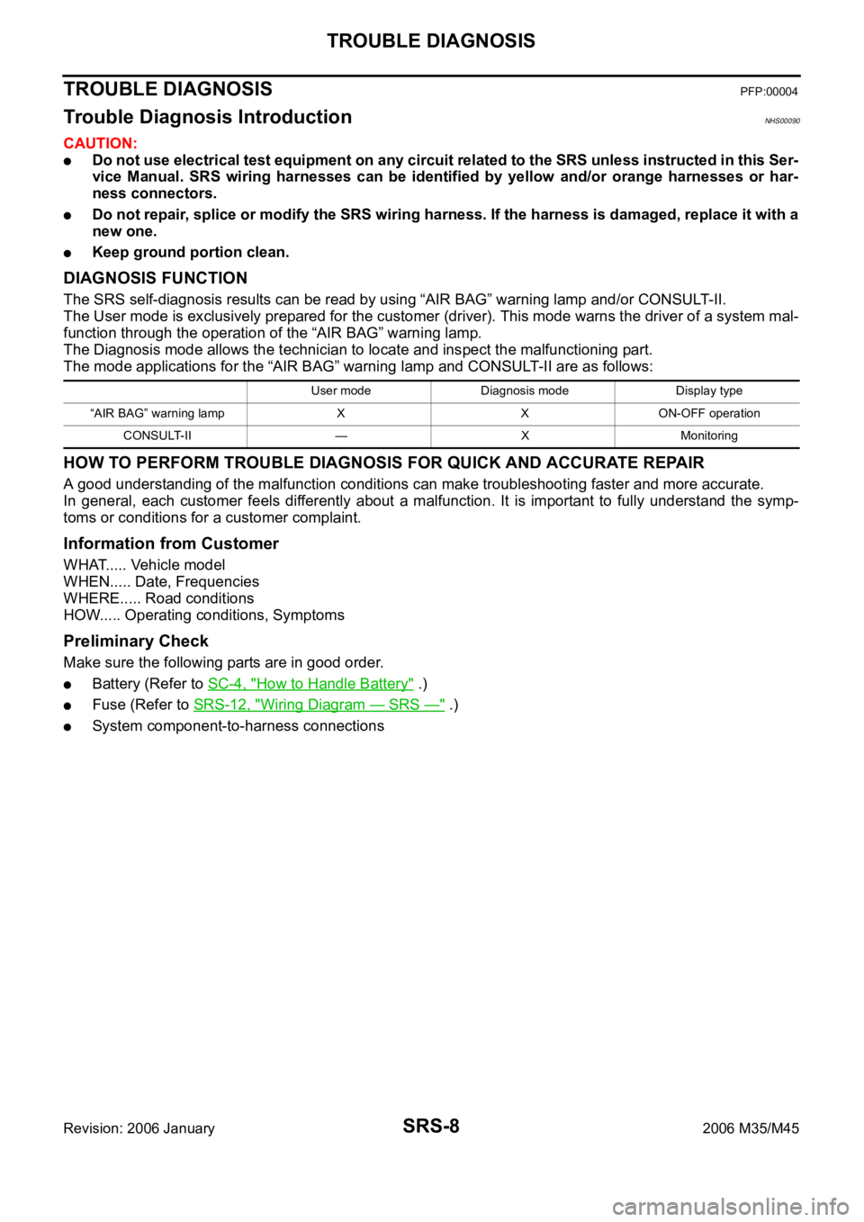
DIAGNOSIS FUNCTION
The SRS self-diagnosis results can be read by using “AIR BAG” warning lamp and/or CONSULT-II.
The User mode is exclusively prepared for the customer (driver). This mode warns the driver of a system mal-
function through the operation of the “AIR BAG” warning lamp.
The Diagnosis mode allows the technician to locate and inspect the malfunctioning part.
The mode applications for the “AIR BAG” warning lamp and CONSULT-II are as follows:
HOW TO PERFORM TROUBLE DIAGNOSIS FOR QUICK AND ACCURATE REPAIR
A good understanding of the malfunction conditions can make troubleshooting faster and more accurate.
In general, each customer feels differently about a malfunction. It is important to fully understand the symp-
toms or conditions for a customer complaint.
Information from Customer
WHAT..... Vehicle model
WHEN..... Date, Frequencies
WHERE..... Road conditions
HOW..... Operating conditions, Symptoms
Preliminary Check
Make sure the following parts are in good order.
Battery (Refer to SC-4, "How to Handle Battery" .)
Fuse (Refer to SRS-12, "Wiring Diagram — SRS —" .)
System component-to-harness connections
User mode Diagnosis mode Display type
“AIR BAG” warning lamp X X ON-OFF operation
CONSULT-II — X Monitoring