2006 INFINITI M35 warning
[x] Cancel search: warningPage 4652 of 5621
TURN SIGNAL AND HAZARD WARNING LAMPS
LT-225
C
D
E
F
G
H
I
J
L
MA
B
LT
Revision: 2006 January2006 M35/M45
Turn Signal Lamp Does Not OperateNKS003RU
1. CHECK BULB
Check bulb standard of each turn signal lamp is correct.
OK or NG
OK >> GO TO 2.
NG >> Replace turn signal lamp bulb.
2. CHECK COMBINATION SWITCH INPUT SIGNAL
With CONSULT-II
1. Select “BCM” on CONSULT-II. Select “FLASHER” on “SELECT
TEST ITEM” screen.
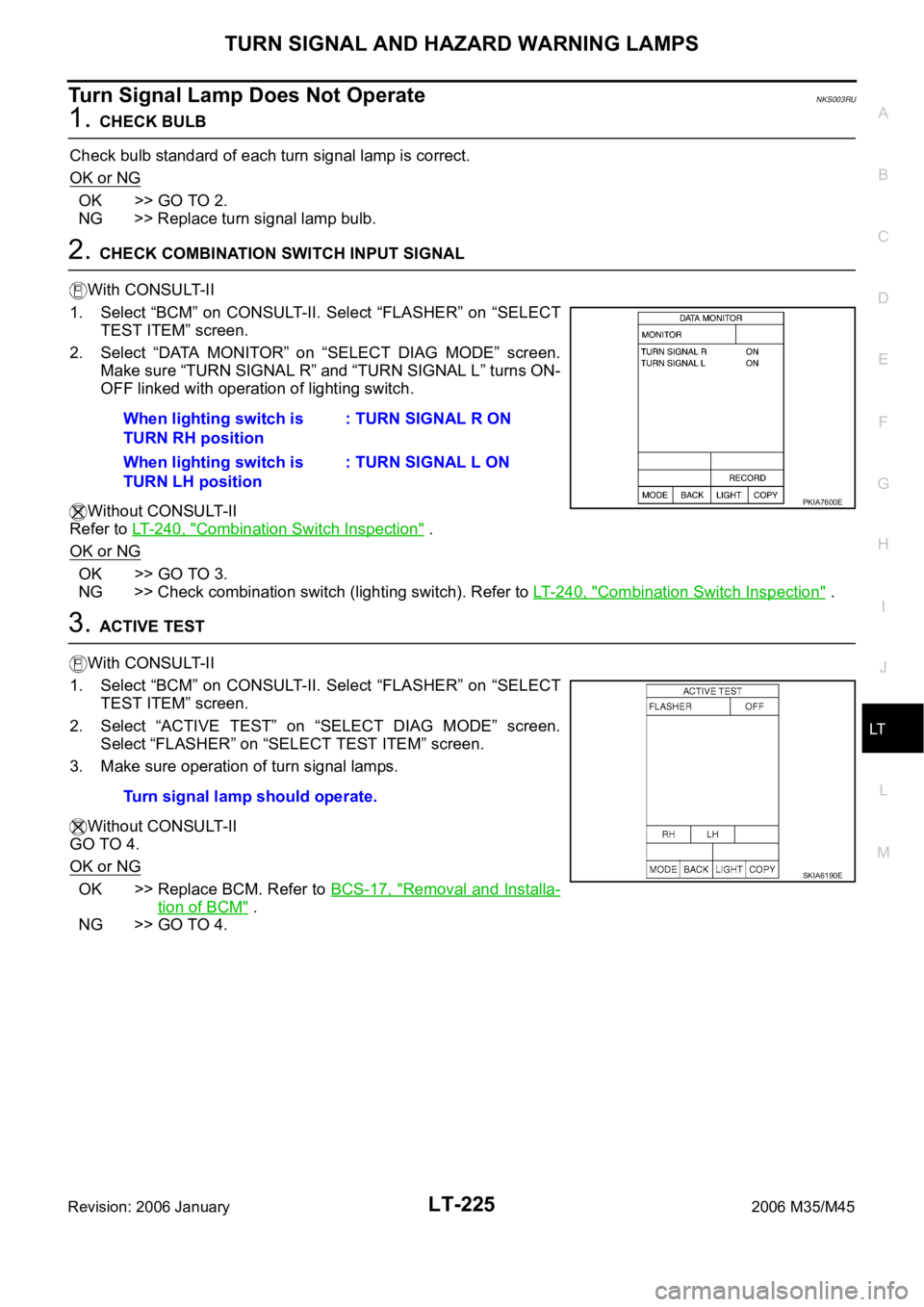
2. Select “DATA MONITOR” on “SELECT DIAG MODE” screen.
Make sure “TURN SIGNAL R” and “TURN SIGNAL L” turns ON-
OFF linked with operation of lighting switch.
Without CONSULT-II
Refer to LT-240, "
Combination Switch Inspection" .
OK or NG
OK >> GO TO 3.
NG >> Check combination switch (lighting switch). Refer to LT- 2 4 0 , "
Combination Switch Inspection" .
3. ACTIVE TEST
With CONSULT-II
1. Select “BCM” on CONSULT-II. Select “FLASHER” on “SELECT
TEST ITEM” screen.
2. Select “ACTIVE TEST” on “SELECT DIAG MODE” screen.
Select “FLASHER” on “SELECT TEST ITEM” screen.
3. Make sure operation of turn signal lamps.
Without CONSULT-II
GO TO 4.
OK or NG
OK >> Replace BCM. Refer to BCS-17, "Removal and Installa-
tion of BCM" .
NG >> GO TO 4.When lighting switch is
TURN RH position: TURN SIGNAL R ON
When lighting switch is
TURN LH position: TURN SIGNAL L ON
PKIA7600E
Turn signal lamp should operate.
SKIA6190E
Page 4653 of 5621
LT-226
TURN SIGNAL AND HAZARD WARNING LAMPS
Revision: 2006 January2006 M35/M45
4. CHECK TURN SIGNAL LAMP CIRCUIT
1. Turn ignition switch OFF.
2. Disconnect BCM connector, front combination lamp RH and LH connector, side turn signal lamp RH and
LH connector, rear combination lamp RH and LH connector.
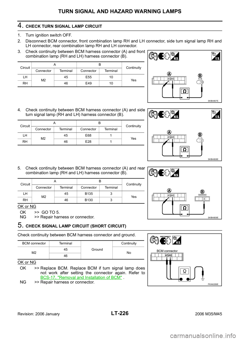
3. Check continuity between BCM harness connector (A) and front
combination lamp (RH and LH) harness connector (B).
4. Check continuity between BCM harness connector (A) and side
turn signal lamp (RH and LH) harness connector (B).
5. Check continuity between BCM harness connector (A) and rear
combination lamp (RH and LH) harness connector (B).
OK or NG
OK >> GO TO 5.
NG >> Repair harness or connector.
5. CHECK SIGNAL LAMP CIRCUIT (SHORT CIRCUIT)
Check continuity between BCM harness connector and ground.
OK or NG
OK >> Replace BCM. Replace BCM if turn signal lamp does
not work after setting the connector again. Refer to
BCS-17, "
Removal and Installation of BCM" .
NG >> Repair harness or connector.
CircuitAB
Continuity
Connector Terminal Connector Terminal
LH
M245 E55 10
Ye s
RH 46 E49 10
SKIB4807E
CircuitAB
Continuity
Connector Terminal Connector Terminal
LH
M245 E68 1
Ye s
RH 46 E28 1
SKIB4808E
CircuitAB
Continuity
Connector Terminal Connector Terminal
LH
M245 B135 3
Ye s
RH 46 B130 3
SKIB4809E
BCM connector Terminal
GroundContinuity
M245
No
46
PKIA6289E
Page 4654 of 5621
TURN SIGNAL AND HAZARD WARNING LAMPS
LT-227
C
D
E
F
G
H
I
J
L
MA
B
LT
Revision: 2006 January2006 M35/M45
Hazard Warning Lamp Does Not Operate But Turn Signal Lamp OperateNKS003RV
1. CHECK CIRCUIT BETWEEN HAZARD SWITCH AND BCM
With CONSULT-II
1. Select “BCM” on CONSULT-II. Select “FLASHER” on “SELECT
TEST ITEM” screen.
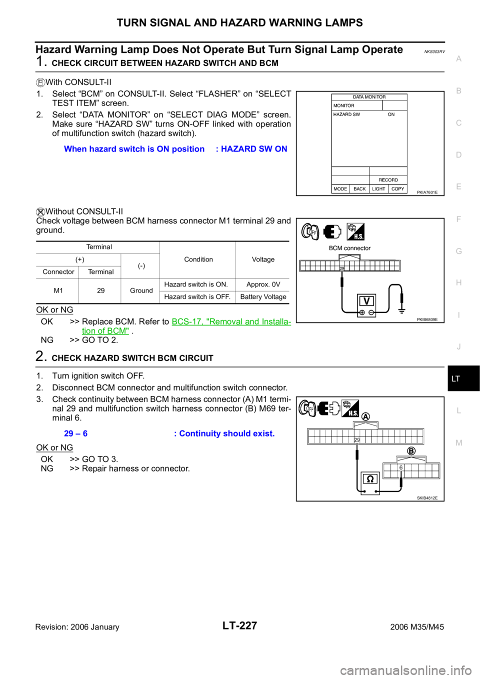
2. Select “DATA MONITOR” on “SELECT DIAG MODE” screen.
Make sure “HAZARD SW” turns ON-OFF linked with operation
of multifunction switch (hazard switch).
Without CONSULT-II
Check voltage between BCM harness connector M1 terminal 29 and
ground.
OK or NG
OK >> Replace BCM. Refer to BCS-17, "Removal and Installa-
tion of BCM" .
NG >> GO TO 2.
2. CHECK HAZARD SWITCH BCM CIRCUIT
1. Turn ignition switch OFF.
2. Disconnect BCM connector and multifunction switch connector.
3. Check continuity between BCM harness connector (A) M1 termi-
nal 29 and multifunction switch harness connector (B) M69 ter-
minal 6.
OK or NG
OK >> GO TO 3.
NG >> Repair harness or connector.When hazard switch is ON position : HAZARD SW ON
PKIA7601E
Terminal
Condition Voltage (+)
(-)
Connector Terminal
M1 29 GroundHazard switch is ON. Approx. 0V
Hazard switch is OFF. Battery Voltage
PKIB6809E
29 – 6 : Continuity should exist.
SKIB4812E
Page 4655 of 5621
LT-228
TURN SIGNAL AND HAZARD WARNING LAMPS
Revision: 2006 January2006 M35/M45
3. CHECK HAZARD SWITCH GROUND CIRCUIT
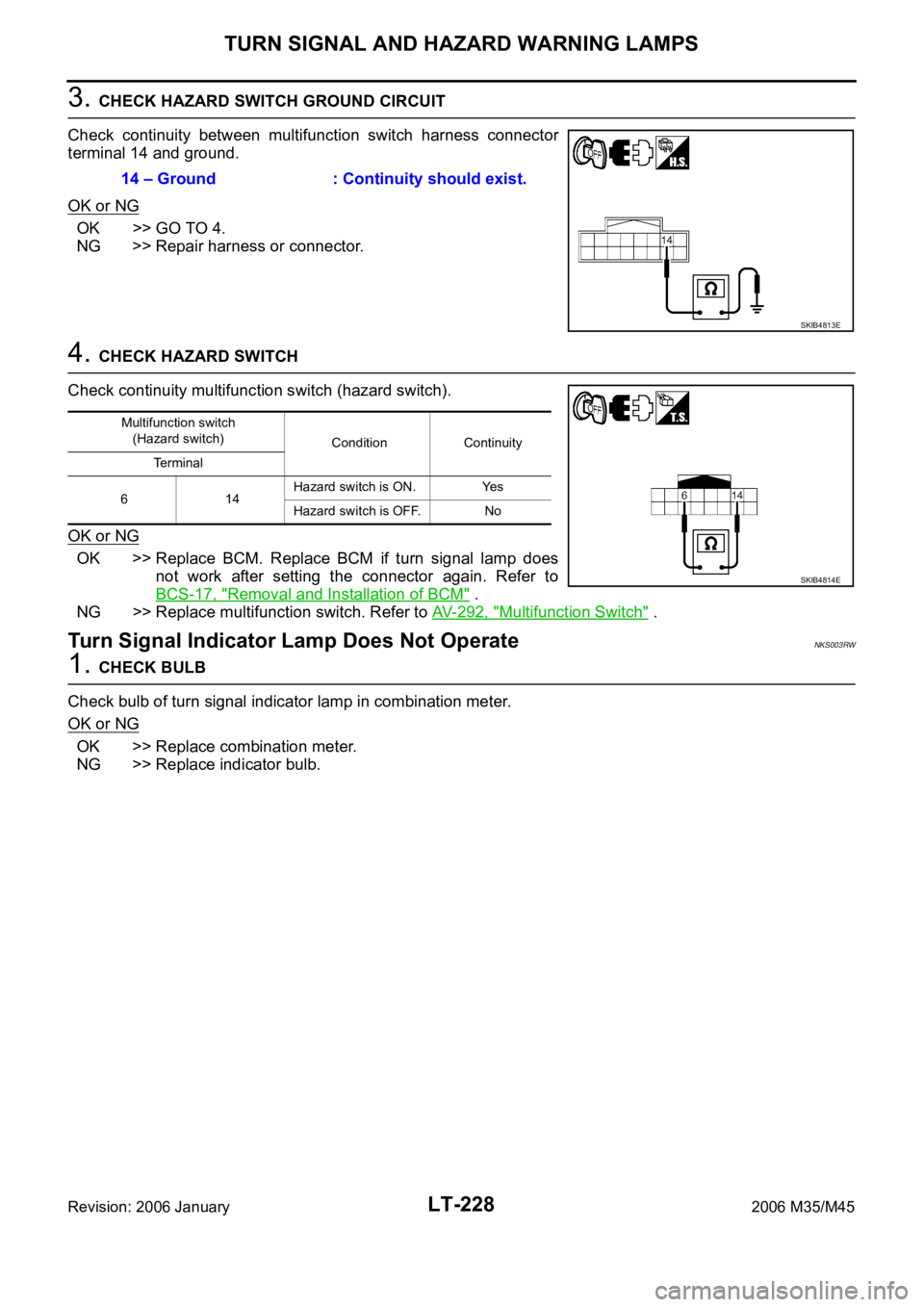
Check continuity between multifunction switch harness connector
terminal 14 and ground.
OK or NG
OK >> GO TO 4.
NG >> Repair harness or connector.
4. CHECK HAZARD SWITCH
Check continuity multifunction switch (hazard switch).
OK or NG
OK >> Replace BCM. Replace BCM if turn signal lamp does
not work after setting the connector again. Refer to
BCS-17, "
Removal and Installation of BCM" .
NG >> Replace multifunction switch. Refer to AV- 2 9 2 , "
Multifunction Switch" .
Turn Signal Indicator Lamp Does Not OperateNKS003RW
1. CHECK BULB
Check bulb of turn signal indicator lamp in combination meter.
OK or NG
OK >> Replace combination meter.
NG >> Replace indicator bulb.14 – Ground : Continuity should exist.
SKIB4813E
Multifunction switch
(Hazard switch)
Condition Continuity
Terminal
614Hazard switch is ON. Yes
Hazard switch is OFF. No
SKIB4814E
Page 4656 of 5621
TURN SIGNAL AND HAZARD WARNING LAMPS
LT-229
C
D
E
F
G
H
I
J
L
MA
B
LT
Revision: 2006 January2006 M35/M45
Bulb Replacement/Removal and Installation of Side Turn Signal LampNKS003RX
: Vehicle front
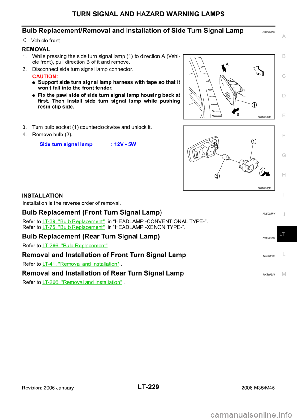
REMOVAL
1. While pressing the side turn signal lamp (1) to direction A (Ve h i -
cle front), pull direction B of it and remove.
2. Disconnect side turn signal lamp connector.
CAUTION:
Support side turn signal lamp harness with tape so that it
won't fall into the front fender.
Fix the pawl side of side turn signal lamp housing back at
first. Then install side turn signal lamp while pushing
resin clip side.
3. Turn bulb socket (1) counterclockwise and unlock it.
4. Remove bulb (2).
INSTALLATION
Installation is the reverse order of removal.
Bulb Replacement (Front Turn Signal Lamp)NKS003RY
Refer to LT- 3 9 , "Bulb Replacement" in “HEADLAMP -CONVENTIONAL TYPE-”.
Refer to LT- 7 5 , "
Bulb Replacement" in “HEADLAMP -XENON TYPE-”.
Bulb Replacement (Rear Turn Signal Lamp)NKS003RZ
Refer to LT-266, "Bulb Replacement" .
Removal and Installation of Front Turn Signal LampNKS003S0
Refer to LT- 4 1 , "Removal and Installation" .
Removal and Installation of Rear Turn Signal Lamp NKS003S1
Refer to LT-266, "Removal and Installation" .
SKIB4184E
Side turn signal lamp : 12V - 5W
SKIB4185E
Page 4723 of 5621

LT-296
ILLUMINATION
Revision: 2006 January2006 M35/M45
ILLUMINATION OPERATION BY LIGHTING SWITCH
With the lighting switch in the 1ST or 2ND position (or if the auto light system is activated), the BCM receives
input signal requesting the illumination lamps to illuminate. This input signal is communicated to the IPDM E/R
across the CAN communication lines. The CPU located in the IPDM E/R controls the tail lamp relay coil,
which, when energized, directs power
through IPDM E/R terminal 21
to combination meter terminal 13
to LDW switch (illumination) terminal 5 (with lane departure warning)
to VDC off switch (illumination) terminal 3
to trunk lid opener switch (illumination) terminal 3
to combination switch (spiral cable) terminal 24
to door mirror remote control switch (illumination) terminal 16
to AFS switch (illumination) terminal 5 (with AFS)
to rear sunshade front switch (illumination) terminal 5 (with rear control switch)
to A/T illumination terminal 1
to snow mode switch (illumination) terminal 5 (AWD models)
to rear control cancel switch (illumination) terminal 4 (with rear control switch)
to clock terminal 3
to multifunction switch terminal 3
to audio unit terminal 9
to DVD player terminal 18 (with DVD player)
to NAVI control unit terminal 61 (with navigation system)
to AV control unit terminal 61 (without navigation system)
to climate controlled seat switch driver side (illumination) terminal 7 (with climate controlled seat)
to climate controlled seat switch passenger side (illumination) terminal 7 (with climate controlled seat)
to ashtray illumination (rear LH) terminal 1
to ashtray illumination (rear RH) terminal 1
to illumination control switch terminal 1
to cigarette lighter socket (illumination) terminal 2
to map lamp (illumination) terminal 8
to power window main switch illumination terminal 1
to glove box lamp terminal 1
to rear control switch terminal 2
to rear power seat switch RH (illumination) terminal 4 (with rear control switch)
to rear heated seat switch RH (illumination) terminal 7 (with rear control switch)
to rear sunshade cancel relay terminal 6 (with rear control switch)
to automatic return cancel switch (illumination) terminal 4 (with rear control switch)
to rear power seat switch LH (illumination) terminal 4 (with rear control switch) and
to rear heated seat switch LH (illumination) terminal 7 (with rear control switch),
through Intelligent Key unit terminal 12
to push button ignition switch (illumination) terminal 3.
Ground is supplied
to combination meter terminal 14
to combination meter terminal 9, 10 and 11
to push button ignition switch (illumination) terminal 2
to LDW switch (illumination) terminal 4 (with lane departure warning)
to VDC off switch (illumination) terminal 4
to trunk lid opener switch (illumination) terminal 4
to combination switch (spiral cable) terminal 25
Page 4782 of 5621

GENERAL MAINTENANCE
MA-5
C
D
E
F
G
H
I
J
K
MA
B
MA
Revision: 2006 January2006 M35/M45
OUTSIDE THE VEHICLE
The maintenance items listed here should be performed from time to time, unless otherwise specified.
INSIDE THE VEHICLE
The maintenance items listed here should be checked on a regular basis, such as when performing periodic maintenance, cleaning the
vehicle, etc.ItemReference page
TiresCheck the pressure with a gauge, including the spare, at least once a month
and always prior to a long distance trips. Adjust to the specified pressure if
necessary. Check carefully for damage, cuts or excessive wear.—
Wheel nutsWhen checking the tires, make sure no nuts are missing, and check for any
loose nuts. Tighten if necessary.—
WindshieldClean the windshield on a regular basis. Check the windshield at least every
six months for cracks or other damage. Repair as necessary.—
Tire rotationTires should be rotated every 12,000 km (7,500 miles).MA-35
Wheel alignment and
balanceIf the vehicle pulls to either side while driving on a straight and level road, or if
you detect uneven or abnormal tire wear, there may be a need for wheel align-
ment. If the steering wheel or seat vibrates at normal highway speeds, wheel
balancing may be needed.MA-33,
FSU-6
(2WD),
FSU-23
(AWD)
Windshield wiper
bladesCheck for cracks or wear if they do not wipe properly. —
Doors and engine
hoodCheck that all doors and the engine hood operate smoothly as well as the
trunk lid. Also make sure that all latches lock securely. Lubricate if necessary.
Make sure that the secondary latch keeps the hood from opening when the pri-
mary latch is released.
When driving in areas using road salt or other corrosive materials, check lubri-
cation frequently.MA-38
LampsMake sure that the headlamps, stop lamps, tail lamps, turn signal lamps, and
other lamps are all operating properly and installed securely. Also check head-
lamp aim. Clean the headlamps on a regular basis. —
ItemReference page
Warning lamps and
chimesMake sure that all warning lamps and chimes are operating properly. —
Windshield wiper and
washerCheck that the wipers and washer operate properly and that the wipers do not
streak.—
Windshield defrosterCheck that the air comes out of the defroster outlets properly and in sufficient
quantity when operating the heater or air conditioner.—
Steering wheelCheck that it has the specified play. Be sure to check for changes in the steer-
ing condition, such as excessive play, hard steering or strange noises.
Free play: Less than 35 mm (1.38 in)—
SeatsCheck seat position controls such as seat adjusters, seatback recliner, etc. to
make sure they operate smoothly and that all latches lock securely in every
position. Check that the head restrains move up and down smoothly and that
the locks (if equipped) hold securely in all latched positions. Check that the
latches lock securely for folding-down rear seatbacks.—
Seat beltsCheck that all parts of the seat belt system (e.g. buckles, anchors, adjusters
and retractors) operate properly and smoothly, and are installed securely.
Check the belt webbing for cuts, fraying, wear or damage.MA-39
Accelerator pedalCheck the pedal for smooth operation and make sure the pedal does not catch
or require uneven effort. Keep the floor mats away from the pedal.—
BrakesCheck that the brake does not pull the vehicle to one side when applied. —
Brake pedal and
boosterCheck the pedal for smooth operation and make sure it has the proper dis-
tance under it when depressed fully. Check the brake booster function. Be
sure to keep the floor mats away from the pedal.BR-6
, BR-18
Page 4827 of 5621

PB-8
SERVICE DATA AND SPECIFICATIONS (SDS)
Revision: 2006 January2006 M35/M45
SERVICE DATA AND SPECIFICATIONS (SDS)PFP:00030
Parking Drum Brake NFS000PW
Parking Brake ControlNFS000PX
Ty p eDS17HE
Brake liningStandard thickness 3.2 mm (0.126 in)
Repair limit thickness 1.5 mm (0.059 in)
Drum (disc)Standard inner diameter 172 mm (6.77 in) dia.
Maximum inner diameter 173 mm (6.81 in) dia.
Control typeFoot pedal
Number of notches [under force of 196 N (20 kg, 44 lb)] 3
4 notches
Number of notches when parking brake warning lamp switch comes on 1 notch