2006 INFINITI M35 tow
[x] Cancel search: towPage 3021 of 5621
EI-16
FRONT GRILLE
Revision: 2006 January2006 M35/M45
FRONT GRILLEPFP:62310
Removal and InstallationNIS0024G
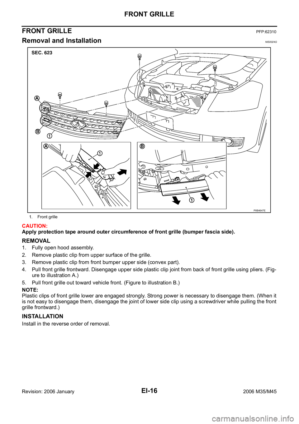
CAUTION:
Apply protection tape around outer circumference of front grille (bumper fascia side).
REMOVAL
1. Fully open hood assembly.
2. Remove plastic clip from upper surface of the grille.
3. Remove plastic clip from front bumper upper side (convex part).
4. Pull front grille frontward. Disengage upper side plastic clip joint from back of front grille using pliers. (Fig-
ure to illustration A.)
5. Pull front grille out toward vehicle front. (Figure to illustration B.)
NOTE:
Plastic clips of front grille lower are engaged strongly. Strong power is necessary to disengage them. (When it
is not easy to disengage them, disengage the joint of lower side clip using a screwdriver while pulling the front
grille frontward.)
INSTALLATION
Install in the reverse order of removal.
1. Front grille
PIIB4647E
Page 3040 of 5621
DOOR FINISHER
EI-35
C
D
E
F
G
H
J
K
L
MA
B
EI
Revision: 2006 January2006 M35/M45
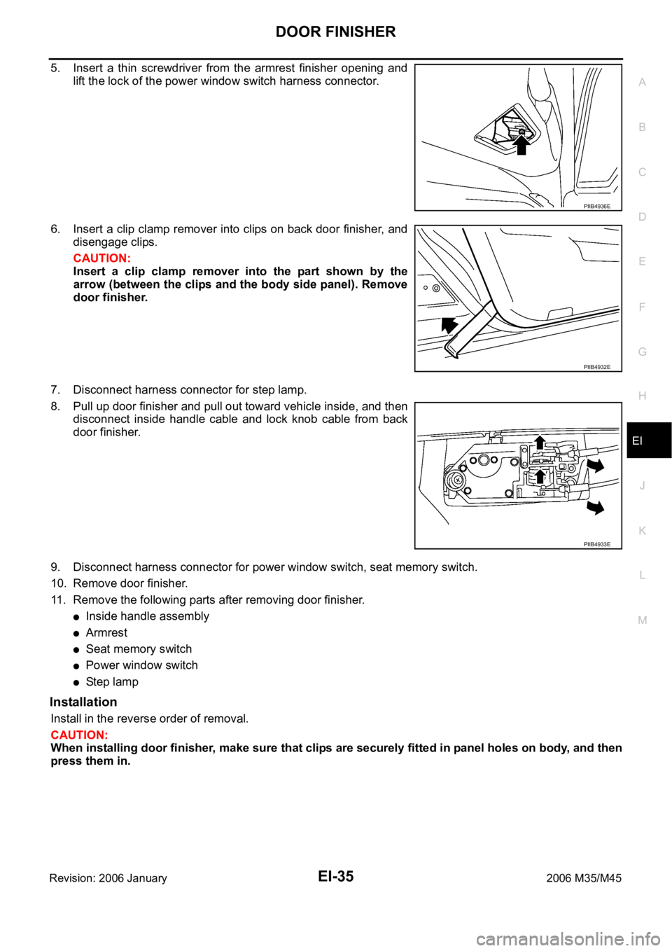
5. Insert a thin screwdriver from the armrest finisher opening and
lift the lock of the power window switch harness connector.
6. Insert a clip clamp remover into clips on back door finisher, and
disengage clips.
CAUTION:
Insert a clip clamp remover into the part shown by the
arrow (between the clips and the body side panel). Remove
door finisher.
7. Disconnect harness connector for step lamp.
8. Pull up door finisher and pull out toward vehicle inside, and then
disconnect inside handle cable and lock knob cable from back
door finisher.
9. Disconnect harness connector for power window switch, seat memory switch.
10. Remove door finisher.
11. Remove the following parts after removing door finisher.
Inside handle assembly
Armrest
Seat memory switch
Power window switch
St e p l am p
Installation
Install in the reverse order of removal.
CAUTION:
When installing door finisher, make sure that clips are securely fitted in panel holes on body, and then
press them in.
PIIB4936E
PIIB4932E
PIIB4933E
Page 3047 of 5621
EI-42
REAR PARCEL SHELF FINISHER
Revision: 2006 January2006 M35/M45
REAR PARCEL SHELF FINISHERPFP:79910
Removal and InstallationNIS0024W
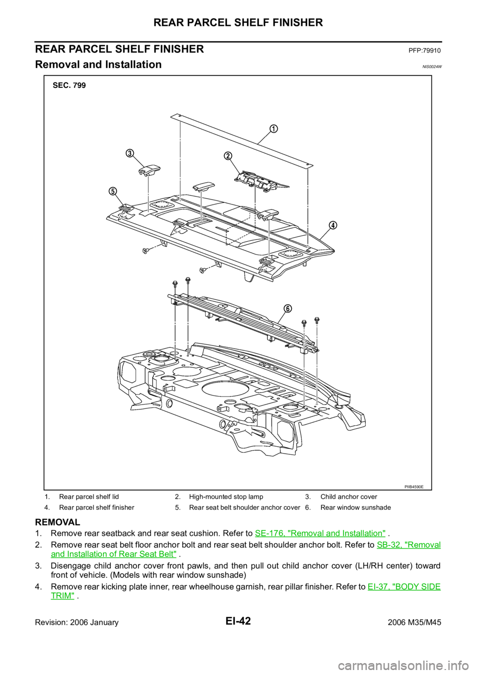
REMOVAL
1. Remove rear seatback and rear seat cushion. Refer to SE-176, "Removal and Installation" .
2. Remove rear seat belt floor anchor bolt and rear seat belt shoulder anchor bolt. Refer to SB-32, "
Removal
and Installation of Rear Seat Belt" .
3. Disengage child anchor cover front pawls, and then pull out child anchor cover (LH/RH center) toward
front of vehicle. (Models with rear window sunshade)
4. Remove rear kicking plate inner, rear wheelhouse garnish, rear pillar finisher. Refer to EI-37, "
BODY SIDE
TRIM" .
1. Rear parcel shelf lid 2. High-mounted stop lamp 3. Child anchor cover
4. Rear parcel shelf finisher 5. Rear seat belt shoulder anchor cover 6. Rear window sunshade
PIIB4590E
Page 3059 of 5621
EI-54
HEADLINING
Revision: 2006 January2006 M35/M45
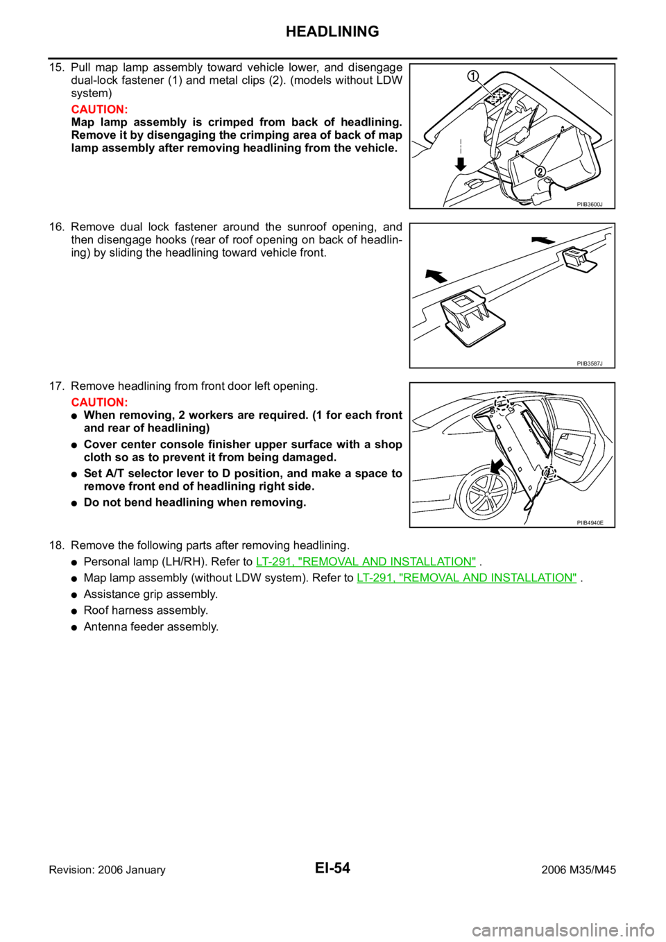
15. Pull map lamp assembly toward vehicle lower, and disengage
dual-lock fastener (1) and metal clips (2). (models without LDW
system)
CAUTION:
Map lamp assembly is crimped from back of headlining.
Remove it by disengaging the crimping area of back of map
lamp assembly after removing headlining from the vehicle.
16. Remove dual lock fastener around the sunroof opening, and
then disengage hooks (rear of roof opening on back of headlin-
ing) by sliding the headlining toward vehicle front.
17. Remove headlining from front door left opening.
CAUTION:
When removing, 2 workers are required. (1 for each front
and rear of headlining)
Cover center console finisher upper surface with a shop
cloth so as to prevent it from being damaged.
Set A/T selector lever to D position, and make a space to
remove front end of headlining right side.
Do not bend headlining when removing.
18. Remove the following parts after removing headlining.
Personal lamp (LH/RH). Refer to LT-291, "REMOVAL AND INSTALLATION" .
Map lamp assembly (without LDW system). Refer to LT- 2 9 1 , "REMOVAL AND INSTALLATION" .
Assistance grip assembly.
Roof harness assembly.
Antenna feeder assembly.
PIIB3600J
PIIB3587J
PIIB4940E
Page 3368 of 5621
FRONT DRIVE SHAFT
FAX-9
C
E
F
G
H
I
J
K
L
MA
B
FA X
Revision: 2006 January2006 M35/M45
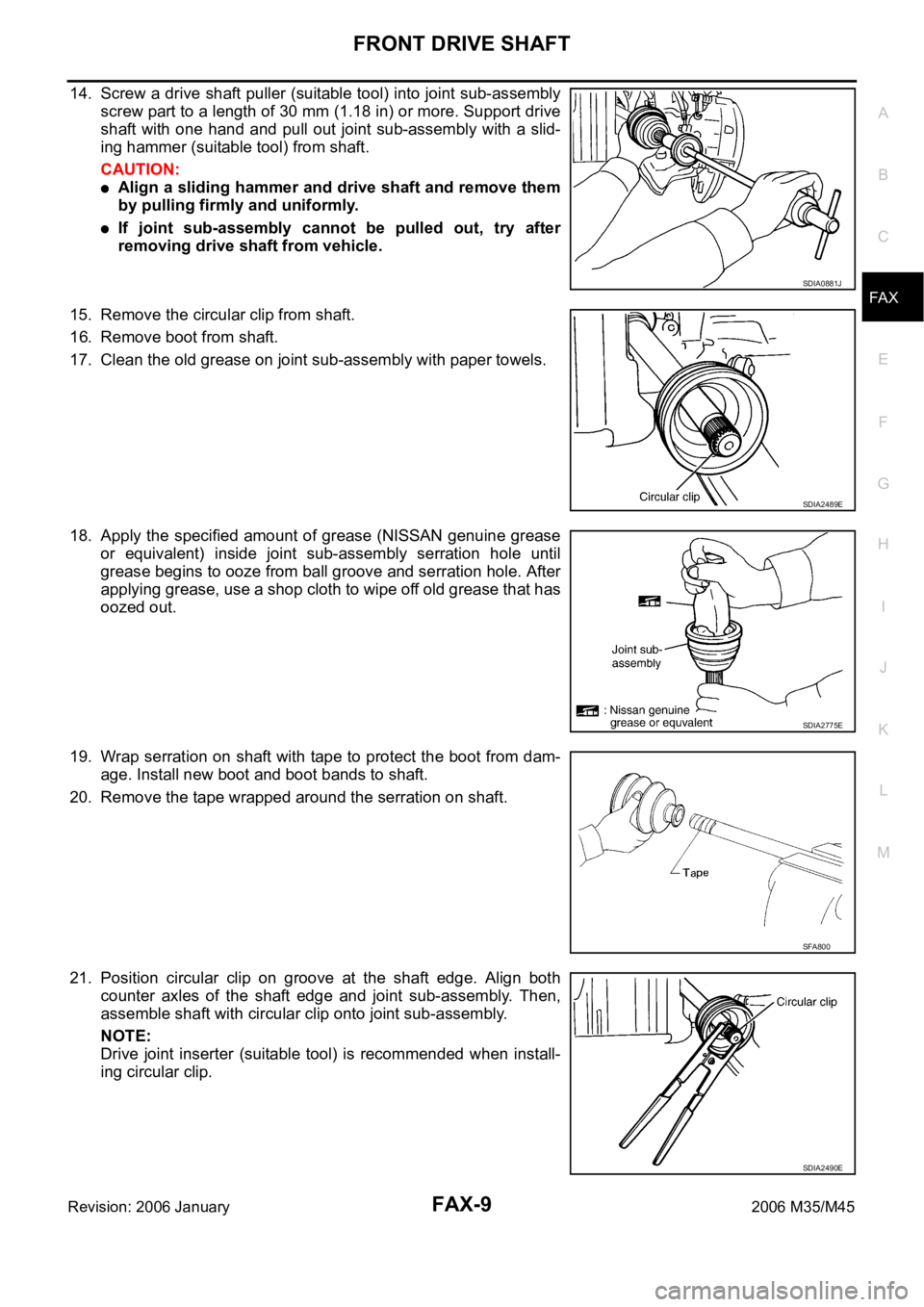
14. Screw a drive shaft puller (suitable tool) into joint sub-assembly
screw part to a length of 30 mm (1.18 in) or more. Support drive
shaft with one hand and pull out joint sub-assembly with a slid-
ing hammer (suitable tool) from shaft.
CAUTION:
Align a sliding hammer and drive shaft and remove them
by pulling firmly and uniformly.
If joint sub-assembly cannot be pulled out, try after
removing drive shaft from vehicle.
15. Remove the circular clip from shaft.
16. Remove boot from shaft.
17. Clean the old grease on joint sub-assembly with paper towels.
18. Apply the specified amount of grease (NISSAN genuine grease
or equivalent) inside joint sub-assembly serration hole until
grease begins to ooze from ball groove and serration hole. After
applying grease, use a shop cloth to wipe off old grease that has
oozed out.
19. Wrap serration on shaft with tape to protect the boot from dam-
age. Install new boot and boot bands to shaft.
20. Remove the tape wrapped around the serration on shaft.
21. Position circular clip on groove at the shaft edge. Align both
counter axles of the shaft edge and joint sub-assembly. Then,
assemble shaft with circular clip onto joint sub-assembly.
NOTE:
Drive joint inserter (suitable tool) is recommended when install-
ing circular clip.
SDIA0881J
SDIA2489E
SDIA2775E
SFA800
SDIA2490E
Page 3373 of 5621
FAX-14
FRONT DRIVE SHAFT
Revision: 2006 January2006 M35/M45
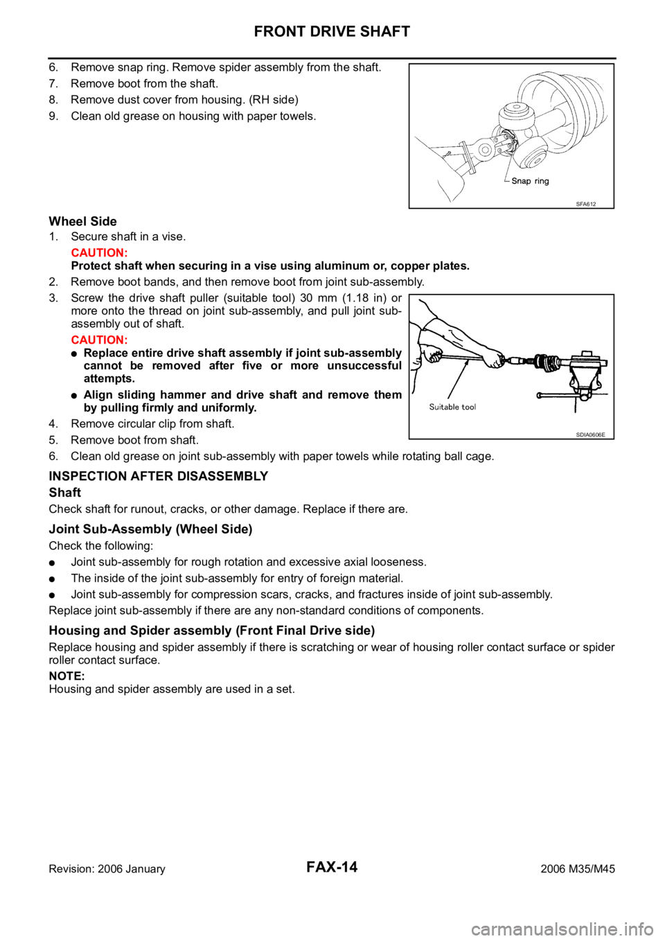
6. Remove snap ring. Remove spider assembly from the shaft.
7. Remove boot from the shaft.
8. Remove dust cover from housing. (RH side)
9. Clean old grease on housing with paper towels.
Wheel Side
1. Secure shaft in a vise.
CAUTION:
Protect shaft when securing in a vise using aluminum or, copper plates.
2. Remove boot bands, and then remove boot from joint sub-assembly.
3. Screw the drive shaft puller (suitable tool) 30 mm (1.18 in) or
more onto the thread on joint sub-assembly, and pull joint sub-
assembly out of shaft.
CAUTION:
Replace entire drive shaft assembly if joint sub-assembly
cannot be removed after five or more unsuccessful
attempts.
Align sliding hammer and drive shaft and remove them
by pulling firmly and uniformly.
4. Remove circular clip from shaft.
5. Remove boot from shaft.
6. Clean old grease on joint sub-assembly with paper towels while rotating ball cage.
INSPECTION AFTER DISASSEMBLY
Shaft
Check shaft for runout, cracks, or other damage. Replace if there are.
Joint Sub-Assembly (Wheel Side)
Check the following:
Joint sub-assembly for rough rotation and excessive axial looseness.
The inside of the joint sub-assembly for entry of foreign material.
Joint sub-assembly for compression scars, cracks, and fractures inside of joint sub-assembly.
Replace joint sub-assembly if there are any non-standard conditions of components.
Housing and Spider assembly (Front Final Drive side)
Replace housing and spider assembly if there is scratching or wear of housing roller contact surface or spider
roller contact surface.
NOTE:
Housing and spider assembly are used in a set.
SFA612
SDIA0606E
Page 3464 of 5621
GI-1
GENERAL INFORMATION
A GENERAL INFORMATION
CONTENTS
C
D
E
F
G
H
I
J
K
L
MB
GI
SECTION GI
Revision: 2006 January2006 M35/M45
GENERAL INFORMATION
PRECAUTIONS .......................................................... 3
Description ............................................................... 3
Precautions for Supplemental Restraint System
(SRS) “AIR BAG” and “SEAT BELT PRE-TEN-
SIONER” .................................................................. 3
Precautions for NVIS/IVIS (NISSAN/INFINITI
VEHICLE IMMOBILIZER SYSTEM - NATS) (If
Equipped) ................................................................. 3
Precautions Necessary for Steering Wheel Rotation
After Battery Disconnect .......................................... 4
OPERATION PROCEDURE ................................. 4
Precautions for Procedures without Cowl Top Cover ..... 4
General Precautions ................................................ 4
Precautions for Three Way Catalyst ......................... 6
Precautions for Fuel (Unleaded Premium Gasoline
Recommended) ...................................................
..... 6
Precautions for Fuel (Unleaded Premium Gasoline
Required) ................................................................. 6
Precautions for Multiport Fuel Injection System or
Engine Control System ............................................ 7
Precautions for Hoses .............................................. 7
HOSE REMOVAL AND INSTALLATION ............... 7
HOSE CLAMPING ................................................ 7
Precautions for Engine Oils ...................................... 8
HEALTH PROTECTION PRECAUTIONS ............. 8
Precautions for Air Conditioning ............................... 8
HOW TO USE THIS MANUAL ................................... 9
Description ............................................................... 9
Terms ....................................................................... 9
Units ......................................................................... 9
Contents ................................................................... 9
Relation between Illustrations and Descriptions .... 10
Components ............................................................ 11
SYMBOLS ........................................................
.... 11
How to Follow Trouble Diagnoses .......................... 12
DESCRIPTION .................................................... 12
HOW TO FOLLOW TEST GROUPS IN TROU-
BLE DIAGNOSES ............................................... 12
HARNESS WIRE COLOR AND CONNECTOR
NUMBER INDICATION ....................................... 13KEY TO SYMBOLS SIGNIFYING MEASURE-
MENTS OR PROCEDURES ............................... 14
How to Read Wiring Diagrams ............................... 16
CONNECTOR SYMBOLS ................................... 16
SAMPLE/WIRING DIAGRAM - EXAMPL - .......... 17
DESCRIPTION .................................................... 18
Abbreviations .......................................................... 24
SERVICE INFORMATION FOR ELECTRICAL INCI-
DENT ......................................................................... 25
How to Check Terminal ........................................... 25
CONNECTOR AND TERMINAL PIN KIT ............ 25
HOW TO PROBE CONNECTORS ...................... 25
How to Perform Efficient Diagnosis for an Electrical
Incident ................................................................... 28
WORK FLOW ...................................................... 28
INCIDENT SIMULATION TESTS ........................ 28
CIRCUIT INSPECTION ....................................
... 31
Control Units and Electrical Parts ........................... 36
PRECAUTIONS .................................................. 36
CONSULT-II CHECKING SYSTEM .......................... 38
Description .............................................................. 38
Function and System Application ........................... 38
Nickel Metal Hydride Battery Replacement ............ 39
Checking Equipment .............................................. 39
CONSULT-II Start Procedure .................................. 39
CONSULT-II Data Link Connector (DLC) Circuit .... 40
INSPECTION PROCEDURE .............................. 40
CIRCUIT DIAGRAM ............................................ 41
LIFTING POINT ......................................................... 42
Special Service Tools ............................................. 42
Garage Jack and Safety Stand and 2-Pole Lift ....... 42
Board-On Lift .......................................................... 43
TOW TRUCK TOWING ............................................. 44
Tow Truck Towing ................................................... 44
2WD MODELS .................................................... 44
AWD MODELS .................................................... 45
Vehicle Recovery (Freeing a Stuck Vehicle) ........... 45
FRONT ................................................................ 45
REAR .................................................................. 45
AUTOMATIC TRANSMISSION ........................... 46
Page 3507 of 5621
GI-44
TOW TRUCK TOWING
Revision: 2006 January2006 M35/M45
TOW TRUCK TOWINGPFP:00000
Tow Truck TowingNAS00081
CAUTION:
All applicable state or Provincial (in Canada) laws and local laws regarding the towing operation
must be obeyed.
It is necessary to use proper towing equipment to avoid possible damage to the vehicle during
towing operation. Towing is in accordance with Towing Procedure Manual at dealer.
Always attach safety chains before towing.
When towing, make sure that the transmission, steering system and powertrain are in good order.
If any unit is damaged, dollies must be used.
Never tow an automatic transmission model from the rear (that is backward) with four wheels on
the ground. This may cause serious and expensive damage to the transmission.
2WD MODELS
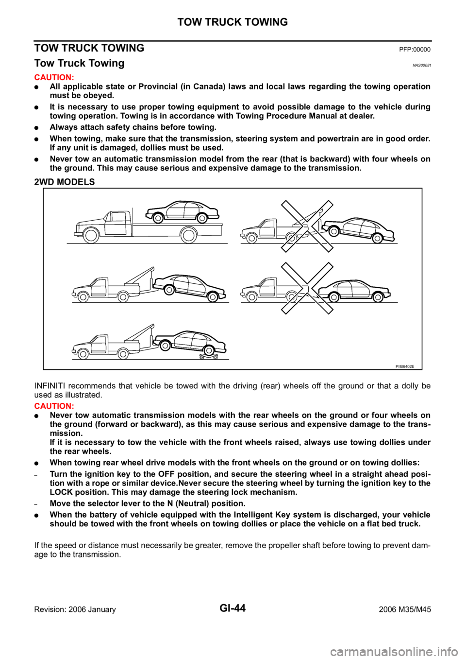
INFINITI recommends that vehicle be towed with the driving (rear) wheels off the ground or that a dolly be
used as illustrated.
CAUTION:
Never tow automatic transmission models with the rear wheels on the ground or four wheels on
the ground (forward or backward), as this may cause serious and expensive damage to the trans-
mission.
If it is necessary to tow the vehicle with the front wheels raised, always use towing dollies under
the rear wheels.
When towing rear wheel drive models with the front wheels on the ground or on towing dollies:
–Turn the ignition key to the OFF position, and secure the steering wheel in a straight ahead posi-
tion with a rope or similar device.Never secure the steering wheel by turning the ignition key to the
LOCK position. This may damage the steering lock mechanism.
–Move the selector lever to the N (Neutral) position.
When the battery of vehicle equipped with the Intelligent Key system is discharged, your vehicle
should be towed with the front wheels on towing dollies or place the vehicle on a flat bed truck.
If the speed or distance must necessarily be greater, remove the propeller shaft before towing to prevent dam-
age to the transmission.
PIIB6402E