2006 INFINITI M35 light
[x] Cancel search: lightPage 3367 of 5621
FAX-8
FRONT DRIVE SHAFT
Revision: 2006 January2006 M35/M45
FRONT DRIVE SHAFTPFP:39100
On-Vehicle Inspection and ServiceNDS000FH
Check drive shaft mounting point and joint for looseness and other damage.
Check boot for cracks and other damage.
CAUTION:
Replace entire drive shaft assembly when noise or vibration occur from drive shaft.
DRIVE SHAFT BOOT REPLACEMENT
1. Remove tires from vehicle with a power tool.
2. Remove wheel sensor from steering knuckle. Refer to BRC-57, "
WHEEL SENSOR" .
CAUTION:
Do not pull on wheel sensor harness.
3. Remove brake hose bracket. Refer to BR-12, "
BRAKE TUBE AND HOSE" .
4. Remove torque menber fixing bolts with a power tool. Hang torque menber in a place where it will not
interfere with work. Refer to BR-23, "
FRONT DISC BRAKE" .
NOTE:
Do not depress brake pedal while brake caliper is removed.
5. Remove disc rotor. Refer to FA X - 5 , "
Removal and Installation" .
6. Remove cotter pin, then loosen hub lock nut with a power tool.
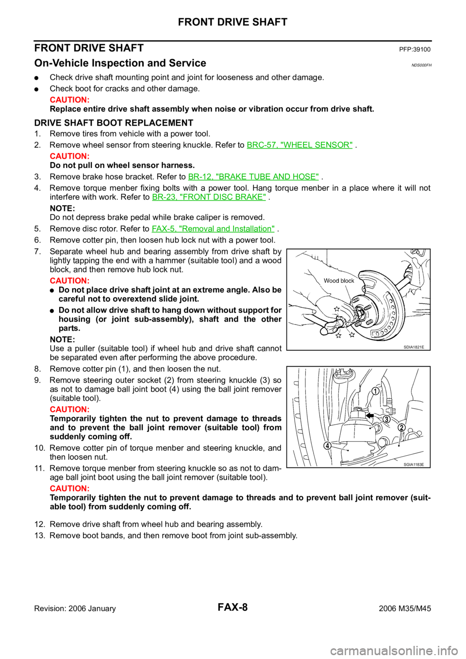
7. Separate wheel hub and bearing assembly from drive shaft by
lightly tapping the end with a hammer (suitable tool) and a wood
block, and then remove hub lock nut.
CAUTION:
Do not place drive shaft joint at an extreme angle. Also be
careful not to overextend slide joint.
Do not allow drive shaft to hang down without support for
housing (or joint sub-assembly), shaft and the other
parts.
NOTE:
Use a puller (suitable tool) if wheel hub and drive shaft cannot
be separated even after performing the above procedure.
8. Remove cotter pin (1), and then loosen the nut.
9. Remove steering outer socket (2) from steering knuckle (3) so
as not to damage ball joint boot (4) using the ball joint remover
(suitable tool).
CAUTION:
Temporarily tighten the nut to prevent damage to threads
and to prevent the ball joint remover (suitable tool) from
suddenly coming off.
10. Remove cotter pin of torque menber and steering knuckle, and
then loosen nut.
11. Remove torque menber from steering knuckle so as not to dam-
age ball joint boot using the ball joint remover (suitable tool).
CAUTION:
Temporarily tighten the nut to prevent damage to threads and to prevent ball joint remover (suit-
able tool) from suddenly coming off.
12. Remove drive shaft from wheel hub and bearing assembly.
13. Remove boot bands, and then remove boot from joint sub-assembly.
SDIA1821E
SGIA1183E
Page 3370 of 5621
FRONT DRIVE SHAFT
FAX-11
C
E
F
G
H
I
J
K
L
MA
B
FA X
Revision: 2006 January2006 M35/M45
34. Install wheel sensor to steering knuckle. Refer to BRC-57, "WHEEL SENSOR" .
35. Tighten the hub lock nut to the specified torque. Refer to FA X - 5 , "
COMPONENT" .
36. Install cotter pin.
37. Install tires to vehicle.
Removal and InstallationNDS000FI
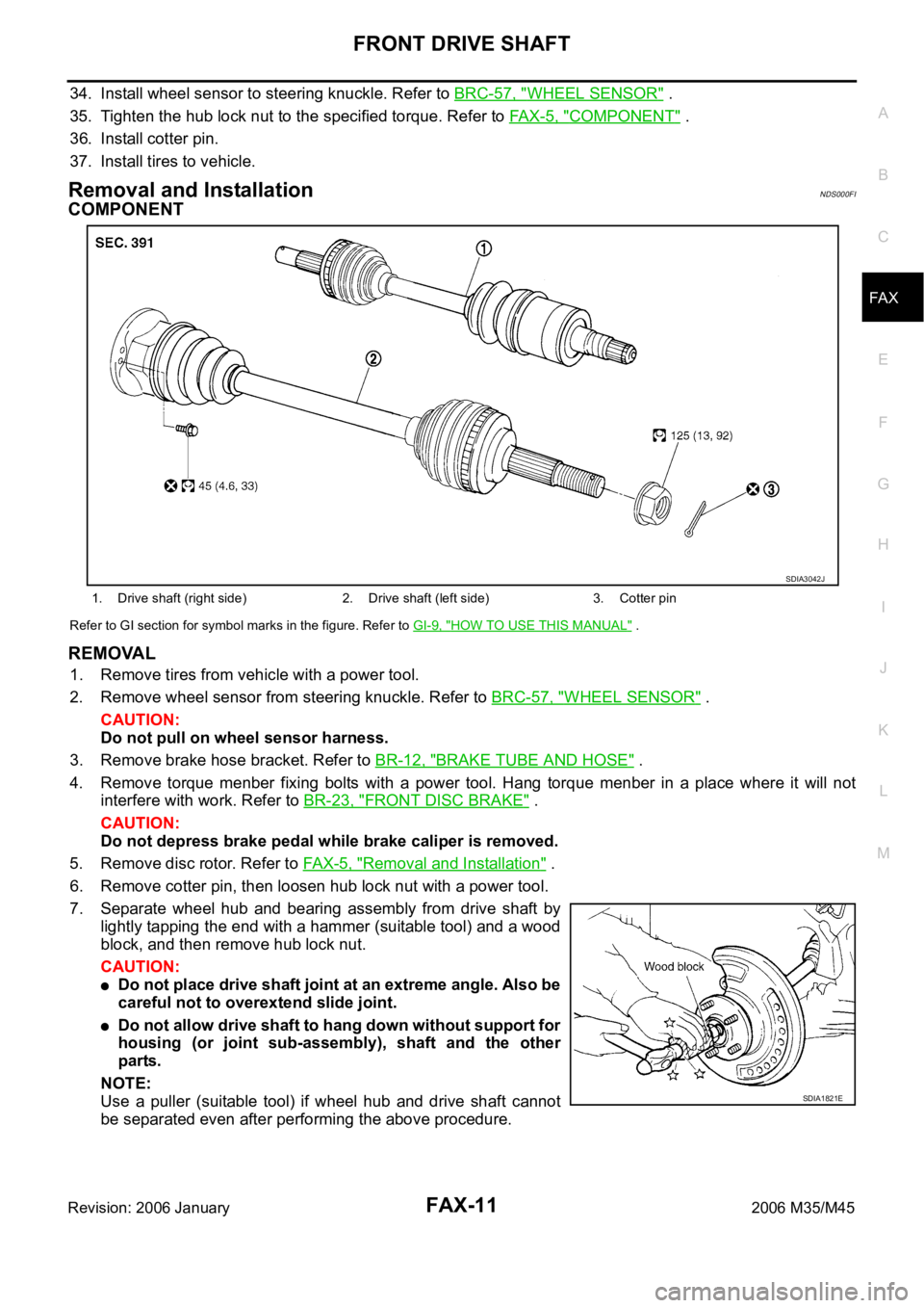
COMPONENT
Refer to GI section for symbol marks in the figure. Refer to GI-9, "HOW TO USE THIS MANUAL" .
REMOVAL
1. Remove tires from vehicle with a power tool.
2. Remove wheel sensor from steering knuckle. Refer to BRC-57, "
WHEEL SENSOR" .
CAUTION:
Do not pull on wheel sensor harness.
3. Remove brake hose bracket. Refer to BR-12, "
BRAKE TUBE AND HOSE" .
4. Remove torque menber fixing bolts with a power tool. Hang torque menber in a place where it will not
interfere with work. Refer to BR-23, "
FRONT DISC BRAKE" .
CAUTION:
Do not depress brake pedal while brake caliper is removed.
5. Remove disc rotor. Refer to FAX-5, "
Removal and Installation" .
6. Remove cotter pin, then loosen hub lock nut with a power tool.
7. Separate wheel hub and bearing assembly from drive shaft by
lightly tapping the end with a hammer (suitable tool) and a wood
block, and then remove hub lock nut.
CAUTION:
Do not place drive shaft joint at an extreme angle. Also be
careful not to overextend slide joint.
Do not allow drive shaft to hang down without support for
housing (or joint sub-assembly), shaft and the other
parts.
NOTE:
Use a puller (suitable tool) if wheel hub and drive shaft cannot
be separated even after performing the above procedure.
1. Drive shaft (right side) 2. Drive shaft (left side) 3. Cotter pin
SDIA3042J
SDIA1821E
Page 3466 of 5621

PRECAUTIONS
GI-3
C
D
E
F
G
H
I
J
K
L
MB
GI
Revision: 2006 January2006 M35/M45
PRECAUTIONSPFP:00001
DescriptionNAS00073
Observe the following precautions to ensure safe and proper servicing. These precautions are not
described in each individual section.
Precautions for Supplemental Restraint System (SRS) “AIR BAG” and “SEAT
BELT PRE-TENSIONER”
NAS00074
The Supplemental Restraint System such as “AIR BAG” and “SEAT BELT PRE-TENSIONER”, used along
with a front seat belt, helps to reduce the risk or severity of injury to the driver and front passenger for certain
types of collision. This system includes seat belt switch inputs and dual stage front air bag modules. The SRS
system uses the seat belt switches to determine the front air bag deployment, and may only deploy one front
air bag, depending on the severity of a collision and whether the front occupants are belted or unbelted.
Information necessary to service the system safely is included in the SRS and SB section of this Service Man-
ual.
WAR NING :
To avoid rendering the SRS inoperative, which could increase the risk of personal injury or death
in the event of a collision which would result in air bag inflation, all maintenance must be per-
formed by an authorized NISSAN/INFINITI dealer.
Improper maintenance, including incorrect removal and installation of the SRS, can lead to per-
sonal injury caused by unintentional activation of the system. For removal of Spiral Cable and Air
Bag Module, see the SRS section.
Do not use electrical test equipment on any circuit related to the SRS unless instructed to in this
Service Manual. SRS wiring harnesses can be identified by yellow and/or orange harnesses or
harness connectors.
Precautions for NVIS/IVIS (NISSAN/INFINITI VEHICLE IMMOBILIZER SYSTEM -
NATS) (If Equipped)
NAS00075
NVIS/IVIS (NATS) will immobilize the engine if someone tries to start it without the registered key of NVIS/IVIS
(NATS).
Both of the originally supplied ignition key IDs have been NVIS/IVIS (NATS) registered.
The security indicator is located on the instrument panel. The indicator blinks when the immobilizer system is
functioning.
Therefore, NVIS/IVIS (NATS) warns outsiders that the vehicle is equipped with the anti-theft system.
When NVIS/IVIS (NATS) detects trouble, the security indicator lamp lights up while ignition switch is in
"ON" position.
This lighting up indicates that the anti-theft is not functioning, so prompt service is required.
When servicing NVIS/IVIS (NATS) (trouble diagnoses, system initialization and additional registration of
other NVIS/IVIS (NATS) ignition key IDs), CONSULT-II hardware and CONSULT-II NVIS/IVIS (NATS)
software is necessary.
Regarding the procedures of NVIS/IVIS (NATS) initialization and NVIS/IVIS (NATS) ignition key ID regis-
tration, refer to CONSULT-II operation manual, NVIS/IVIS (NATS).
Therefore, CONSULT-II NVIS/IVIS (NATS) software (program card and operation manual) must be kept
strictly confidential to maintain the integrity of the anti-theft function.
When servicing NVIS/IVIS (NATS) (trouble diagnoses, system initialization and additional registration of
other NVIS/IVIS (NATS) ignition key IDs), it may be necessary to re-register original key identification.
Therefore, be sure to receive all keys from vehicle owner. A maximum of four or five key IDs can be regis-
tered into NVIS/IVIS (NATS).
When failing to start the engine first time using the key of NVIS/IVIS (NATS), start as follows.
1. Leave the ignition key in "ON" position for approximately 5 seconds.
2. Turn ignition key to "OFF" or "LOCK" position and wait approximately 5 seconds.
3. Repeat step 1 and 2 again.
4. Restart the engine while keeping the key separate from any others on key-chain.
Page 3482 of 5621
HOW TO USE THIS MANUAL
GI-19
C
D
E
F
G
H
I
J
K
L
MB
GI
Revision: 2006 January2006 M35/M45
14 Wire color
This shows a code for the color of the wire.
B = Black
W = White
R = Red
G = Green
L = Blue
Y = Yellow
LG = Light GreenBR = Brown
OR or O = Orange
P = Pink
PU or V (Violet) = Purple
GY or GR = Gray
SB = Sky Blue
CH = Dark Brown
DG = Dark Green
When the wire color is striped, the base color is given first, followed by the stripe color as shown
below:
Example: L/W = Blue with White Stripe
15 Option description
This shows a description of the option abbreviation used on the page.
16 Switch
This shows that continuity exists between terminals 1 and 2 when the switch is in the A posi-
tion. Continuity exists between terminals 1 and 3 when the switch is in the B position.
17 Assembly parts
Connector terminal in component shows that it is a harness incorporated assembly.
18 Cell code
This identifies each page of the wiring diagram by section, system and wiring diagram page
number.
19 Current flow arrow
Arrow indicates electric current flow, especially where the direction of standard flow (vertically
downward or horizontally from left to right) is difficult to follow.
A double arrow “ ” shows that current can flow in either direction depending on cir-
cuit operation.
20 System branch
This shows that the system branches to another system identified by cell code (section and
system).
21 Page crossing
This arrow shows that the circuit continues to another page identified by cell code.
The C will match with the C on another page within the system other than the next or preced-
ing pages.
22 Shielded line
The line enclosed by broken line circle shows shield wire.
23Component box in
wave line
This shows that another part of the component is also shown on another page (indicated by
wave line) within the system.
24 Component name
This shows the name of a component.
25 Connector number
This shows the connector number.
The letter shows which harness the connector is located in.
Example: M : main harness. For detail and to locate the connector, refer to PG section "Main
Harness", “Harness Layout”. A coordinate grid is included for complex harnesses to aid in
locating connectors.
26 Ground (GND)
The line spliced and grounded under wire color shows that ground line is spliced at the
grounded connector.
27 Ground (GND)
This shows the ground connection. For detailed ground distribution information, refer to
"Ground Distribution" in PG section.
28 Connector views
This area shows the connector faces of the components in the wiring diagram on the page.
29 Common component
Connectors enclosed in broken line show that these connectors belong to the same compo-
nent.
30 Connector color
This shows a code for the color of the connector. For code meaning, refer to wire color codes,
Number 14 of this chart.
31Fusible link and fuse
box
This shows the arrangement of fusible link(s) and fuse(s), used for connector views of
"POWER SUPPLY ROUTING" in PG section.
The open square shows current flow in, and the shaded square shows current flow out.
32 Reference area
This shows that more information on the Super Multiple Junction (SMJ) and Joint Connectors
(J/C) exists on the PG section. Refer to "Reference Area" for details. Num-
berItem Description
Page 3492 of 5621
SERVICE INFORMATION FOR ELECTRICAL INCIDENT
GI-29
C
D
E
F
G
H
I
J
K
L
MB
GI
Revision: 2006 January2006 M35/M45
Freezing
Water intrusion
Electrical load
Cold or hot start up
Get a thorough description of the incident from the customer. It is important for simulating the conditions of the
problem.
Vehicle Vibration
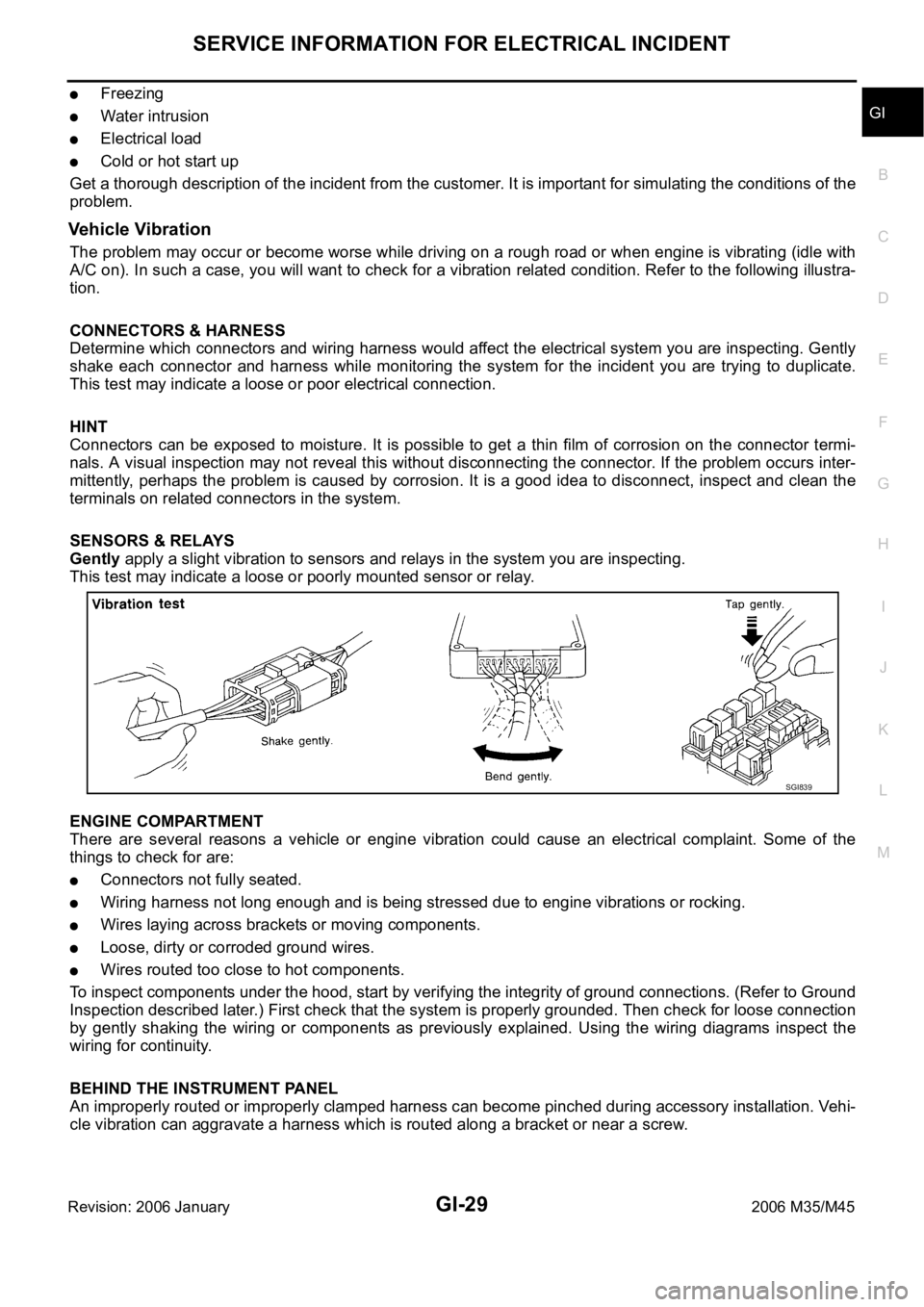
The problem may occur or become worse while driving on a rough road or when engine is vibrating (idle with
A/C on). In such a case, you will want to check for a vibration related condition. Refer to the following illustra-
tion.
CONNECTORS & HARNESS
Determine which connectors and wiring harness would affect the electrical system you are inspecting. Gently
shake each connector and harness while monitoring the system for the incident you are trying to duplicate.
This test may indicate a loose or poor electrical connection.
HINT
Connectors can be exposed to moisture. It is possible to get a thin film of corrosion on the connector termi-
nals. A visual inspection may not reveal this without disconnecting the connector. If the problem occurs inter-
mittently, perhaps the problem is caused by corrosion. It is a good idea to disconnect, inspect and clean the
terminals on related connectors in the system.
SENSORS & RELAYS
Gently apply a slight vibration to sensors and relays in the system you are inspecting.
This test may indicate a loose or poorly mounted sensor or relay.
ENGINE COMPARTMENT
There are several reasons a vehicle or engine vibration could cause an electrical complaint. Some of the
things to check for are:
Connectors not fully seated.
Wiring harness not long enough and is being stressed due to engine vibrations or rocking.
Wires laying across brackets or moving components.
Loose, dirty or corroded ground wires.
Wires routed too close to hot components.
To inspect components under the hood, start by verifying the integrity of ground connections. (Refer to Ground
Inspection described later.) First check that the system is properly grounded. Then check for loose connection
by gently shaking the wiring or components as previously explained. Using the wiring diagrams inspect the
wiring for continuity.
BEHIND THE INSTRUMENT PANEL
An improperly routed or improperly clamped harness can become pinched during accessory installation. Vehi-
cle vibration can aggravate a harness which is routed along a bracket or near a screw.
SGI839
Page 3496 of 5621
SERVICE INFORMATION FOR ELECTRICAL INCIDENT
GI-33
C
D
E
F
G
H
I
J
K
L
MB
GI
Revision: 2006 January2006 M35/M45
no voltage; short is further down the circuit than SW1.
With SW1 closed, relay and solenoid disconnected and the DMM leads across both fuse terminals, check
for voltage.
voltage; short is between SW1 and the relay (point B).
no voltage; short is further down the circuit than the relay.
With SW1 closed, relay contacts jumped with fused jumper wire check for voltage.
voltage; short is down the circuit of the relay or between the relay and the disconnected solenoid (point C).
no voltage; retrace steps and check power to fuse block.
Ground Inspection
Ground connections are very important to the proper operation of electrical and electronic circuits. Ground
connections are often exposed to moisture, dirt and other corrosive elements. The corrosion (rust) can
become an unwanted resistance. This unwanted resistance can change the way a circuit works.
Electronically controlled circuits are very sensitive to proper grounding. A loose or corroded ground can drasti-
cally affect an electronically controlled circuit. A poor or corroded ground can easily affect the circuit. Even
when the ground connection looks clean, there can be a thin film of rust on the surface.
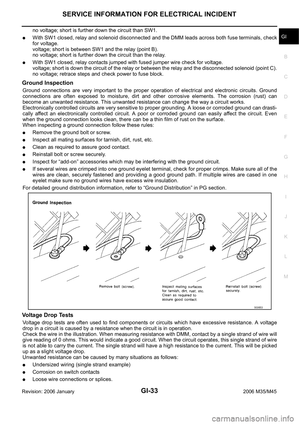
When inspecting a ground connection follow these rules:
Remove the ground bolt or screw.
Inspect all mating surfaces for tarnish, dirt, rust, etc.
Clean as required to assure good contact.
Reinstall bolt or screw securely.
Inspect for “add-on” accessories which may be interfering with the ground circuit.
If several wires are crimped into one ground eyelet terminal, check for proper crimps. Make sure all of the
wires are clean, securely fastened and providing a good ground path. If multiple wires are cased in one
eyelet make sure no ground wires have excess wire insulation.
For detailed ground distribution information, refer to “Ground Distribution” in PG section.
Voltage Drop Tests
Voltage drop tests are often used to find components or circuits which have excessive resistance. A voltage
drop in a circuit is caused by a resistance when the circuit is in operation.
Check the wire in the illustration. When measuring resistance with DMM, contact by a single strand of wire will
give reading of 0 ohms. This would indicate a good circuit. When the circuit operates, this single strand of wire
is not able to carry the current. The single strand will have a high resistance to the current. This will be picked
up as a slight voltage drop.
Unwanted resistance can be caused by many situations as follows:
Undersized wiring (single strand example)
Corrosion on switch contacts
Loose wire connections or splices.
SGI853
Page 3498 of 5621
SERVICE INFORMATION FOR ELECTRICAL INCIDENT
GI-35
C
D
E
F
G
H
I
J
K
L
MB
GI
Revision: 2006 January2006 M35/M45
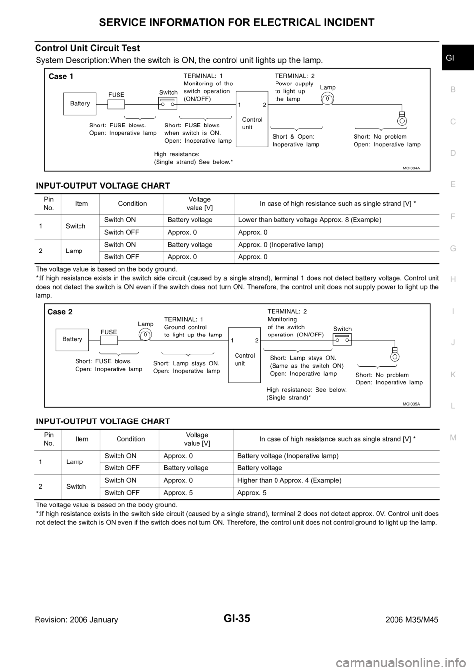
Control Unit Circuit Test
System Description:When the switch is ON, the control unit lights up the lamp.
INPUT-OUTPUT VOLTAGE CHART
The voltage value is based on the body ground.
*:If high resistance exists in the switch side circuit (caused by a single strand), terminal 1 does not detect battery voltage. Control unit
does not detect the switch is ON even if the switch does not turn ON. Therefore, the control unit does not supply power to light up the
lamp.
INPUT-OUTPUT VOLTAGE CHART
The voltage value is based on the body ground.
*:If high resistance exists in the switch side circuit (caused by a single strand), terminal 2 does not detect approx. 0V. Control unit does
not detect the switch is ON even if the switch does not turn ON. Therefore, the control unit does not control ground to light up the lamp.
MGI034A
Pin
No.Item ConditionVoltage
value [V]In case of high resistance such as single strand [V] *
1 SwitchSwitch ON Battery voltage Lower than battery voltage Approx. 8 (Example)
Switch OFF Approx. 0 Approx. 0
2LampSwitch ON Battery voltage Approx. 0 (Inoperative lamp)
Switch OFF Approx. 0 Approx. 0
MGI035A
Pin
No.Item ConditionVoltage
value [V]In case of high resistance such as single strand [V] *
1 LampSwitch ON Approx. 0 Battery voltage (Inoperative lamp)
Switch OFF Battery voltage Battery voltage
2SwitchSwitch ON Approx. 0 Higher than 0 Approx. 4 (Example)
Switch OFF Approx. 5 Approx. 5
Page 3501 of 5621

GI-38
CONSULT-II CHECKING SYSTEM
Revision: 2006 January2006 M35/M45
CONSULT-II CHECKING SYSTEMPFP:00000
DescriptionNAS0007S
CONSULT-II is a hand-held type tester. When it is connected with a diagnostic connector equipped on the
vehicle side, it will communicate with the control unit equipped in the vehicle and then enable various
kinds of diagnostic tests.
Refer to “CONSULT-II Software Operation Manual” for more information.
Function and System Application NAS0007T
x: Applicable
*: NISSAN Anti-Theft System (INFINITI/NISSAN Vehicle Immobilizer System) Diagnostic test
modeFunction
ENGINE
A/T
AIR BAG
METER A/C AMP
BCM
AUTO DRIVE POS.
ABS (Including VDC)
NATS (IVIS/NATS) *
IPDM E/R
ICC
ALL MODE AWD/4WD
INTELLIGENT KEY
LDW
AIR PRESSURE MONITOR
RAS/HICAS
ADAPTIVE LIGHT
PRECRASH SEATBELT
MULTI AV
Work supportThis mode enables a technician to adjust
some devices faster and more accurately by
following the indications on CONSULT-II.x - - - xxx -- x- xxx- x- -
Self-diagnostic
resultsSelf-diagnostic results can be read and
erased quickly.xxxxxxxxxxxxxxxxxx
Trouble diagnos-
tic recordCurrent self-diagnostic results and all trouble
diagnostic records previously stored can be
read.--x---------------
Data monitor Input/Output data in the ECU can be read. x x - x x x x - x xxxxxxxxx
CAN diagnosis
support monitorThe condition of CAN communication line
can be read.xx- xxxx- xxxxxxxxxx
Active testDiagnostic Test Mode in which CONSULT-II
drives some actuators apart from the ECUs
and also shifts some parameters in a speci-
fied range.x- - - xxx -xxxxxxxx- -
DTC & SRT con-
firmationThe results of SRT (System Readiness Test)
and the self-diagnosis status/result can be
confirmed.x- ----------------
DTC work sup-
portThe operating condition to confirm Diagnosis
Trouble Codes can be selected.xx----------------
ECU (ECM/TCM)
part numberECU (ECM/TCM) part number can be read. xx - - xxx -- xxxxxxxxx
ECU discrimi-
nated No.Classification number of a replacement ECU
can be read to prevent an incorrect ECU from
being installed.-- x---------------
Function testThis mode can show results of self-diagnosis
of ECU with either 'OK' or 'NG'. For engines,
more practical tests regarding sensors/
switches and/or actuators are available.xxx---x-----------
Control unit ini-
tializationAll registered ignition key IDs in NATS com-
ponents can be initialized and new IDs can
be registered.-- -----x----------
AV COMM moni-
torThe condition of AV communication can be
Indicated.------------ ---- -x