2006 INFINITI M35 wheel
[x] Cancel search: wheelPage 5193 of 5621

SE-12
AUTOMATIC DRIVE POSITIONER
Revision: 2006 January2006 M35/M45
System DescriptionNIS0025R
The system automatically moves the driver seat, steering and door mirror position by the driver seat con-
trol unit and the automatic drive positioner control unit. The driver seat control unit corresponds with the
automatic drive positioner control unit via UART communication. The driver seat control unit can store the
optimum driving positions (driver seat, steering and door mirror position) for 2 people. If the driver
changes, one-touch operation allows changing to the other driving position.
The driver seat, steering and door mirror position are adjusted automatically to the proper positions for the
driver in different ways: MEMORY OPERATION, EXITING OPERATION, ENTRY OPERATION and
INTELLIGENT KEY INTERLOCK OPERATION.
MANUAL OPERATION
The driving position (seat, steering and door mirror position) can be adjusted with the power seat switch, ADP
steering switch and door mirror control switch.
NOTE:
The door mirrors can be manually operated with the ignition switch in either ACC or ON.
MEMORY OPERATION
The driver seat control unit can store the optimum driving positions (seat, steering and door mirror position) for
2 people. If the front seat position is changed, one-touch (pressing desired memory switch for more than 0.5
second) operation allows changing to the other driving position.
Operation procedure
1. Turn ignition switch ON.
2. Press desired memory switch for 0.5 second. (Indicator LED illuminates.)
3. Driver seat, steering and door mirror will move to the memorized position.
(Indicator LED blinks during adjustment, then illuminates for 5 seconds.)
Operation Condition
If the following conditions are not satisfied, memory switch operation is not performed.
Ignition switch is in ON position.
Driver side power seat switch, ADP steering switch and door mirror control switch are not operated.
Seat memory switch and set switch are not operated.
Output malfunction is not detected.
CAN and UART communications are normal.
A/T selector lever position is in P position.
Detention switch malfunction is not detected.
[Detention switch malfunction is sensed when detention switch remains OFF, vehicle speed is higher than
7 km/H. (4 MPH).]
Input voltage from tilt sensor and telescopic sensor are normal.
NOTE:
The memory operation operates following order.
Function Description
Manual operationThe driving position (seat, steering and door mirror position) can be adjusted with
the power seat switch ADP steering switch or door mirror control switch.
Auto-
matic
operationMemory operation The seat, steering and door mirror move to the stored driving position by pushing
seat memory switch (1 or 2).
Entry/
Exiting
functionExiting operation At exit, the seat moves backward and the steering wheel moves upward.
Entry operationAt entry, the seat and steering wheel returns from exiting position to the previous
driving position before the exiting operation.
Intelligent Key interlock operationPerform memory operation, exiting operation and entry operation by pressing Intel-
ligent Key unlock button.
Page 5194 of 5621

AUTOMATIC DRIVE POSITIONER
SE-13
C
D
E
F
G
H
J
K
L
MA
B
SE
Revision: 2006 January2006 M35/M45
*: Door mirror operation starts with the start of seat sliding operation.
Storing Memory Procedure
1. Turn ignition switch to ON.
2. Shift A/T selector lever to P position.
3. Adjust position of driver seat, steering and mirror position.
4. Press set switch.
Indicator LED for which driver seat positions are already retained in memory is illuminated for 5 sec-
onds.
Indicator LED for which driver seat positions are not retained in memory is illuminated for 0.5 second.
5. Press memory switch for which driver seat positions are to be entered in memory for more than 0.5 sec-
ond within 5 seconds after pressing the set switch (during the indicator LED is illuminated).
To enter driver seat positions in blank memory, indicator LED will be illuminated for 5 seconds.
To modify driver seat positions, indicator LED will be turned OFF for 0.5 second then illuminated for 5
seconds.
6.
If you need setting of INTELLIGENT KEY INTERLOCK OPERATION, continue this procedure.
If you don't need setting of INTELLIGENT KEY INTERLOCK OPERATION, the procedure is finished.
Conform the operations of each part with the MEMORY OPERATION.
7. Press intelligent key unlock button within 5 seconds after pressing memory switch.
(While memory switch LED is illuminated.)
8. Conform the operations of each part with MEMORY OPERATION and INTELLIGENT KEY INTERLOCK
OPERATION.
NOTE:
Driving position is erased from the memory when battery cable is disconnected.
Order of priority Operated portion
1* Seat sliding
2 Steering telescopic
3 Steering wheel tilt
4 Seat reclining
5 Seat lifter (front)
6 Seat lifter (rear)
Page 5197 of 5621

SE-16
AUTOMATIC DRIVE POSITIONER
Revision: 2006 January2006 M35/M45
INITIALIZATION PROCEDURE
After reconnecting battery cable, perform initialization procedure A or B. If initialization has not been per-
formed, EXITING OPERATION will not operate.
Procedure A
1. Turn ignition switch from ACC to OFF position.
2. Driver door switch is ON (open)
OFF (close) ON (open).
3. END
Procedure B
1. Drive the vehicle at more than 25 km/h (16 MPH).
2. END
SETTING CHANGE FUNCTION
The settings of the automatic driving positioner system can be changed, using CONSULT-II and the display
unit in the center of the instrument panel.
: Applicable –: Not applicable
It is possible to set sliding driver seat for entry/exit of vehicle by pressing set switch.
CAN Communication System DescriptionNIS0025S
CAN (Controller Area Network) is a serial communication line for real time application. It is an on-vehicle mul-
tiplex communication line with high data communication speed and excellent error detection ability. Many elec-
tronic control units are equipped onto a vehicle, and each control unit shares information and links with other
control units during operation (not independent). In CAN communication, control units are connected with 2
communication lines (CAN H line, CAN L line) allowing a high rate of information transmission with less wiring.
Each control unit transmits/receives data but selectively reads required data only.
CAN Communication UnitNIS0025T
Refer to LAN-34, "CAN Communication Unit" .
Setting item ContentCONSULT–II
(WORK SUPPORT)Display unitFactory
setting
Change seat sliding volume
settingThe distance at retain operation
can be selected from the following
3 modes.40 mm
—
80 mm —
150 mm —
Change the Entry/Exit seat
slide function settingThe seat sliding turnout and return
at entry/exit can be selected: ON
(operated) – OFF (not operated)ON ON: Indicator lamp ON
OFF OFF: Indicator lamp OFF —
Change the Entry/Exit tilt
steering wheel function settingLift up and backward steering
wheel at entry and exit can be
selected: ON (operated) - OFF (not
operated)ON ON: Indicator lamp ON
OFF OFF: Indicator lamp OFF —
Reset custom settings All settings to default. —Default: Setting button
OFF—
Content Setting change operation Indicator LED
The seat sliding turnout and
steering wheel up/backward at
entry/exit can be operated.
Press the set switch for more than 10 secondsBlinking twice
The seat sliding turnout and
steering wheel up/backward at
entry/exit can be not operated.Blinking ones
Page 5230 of 5621

AUTOMATIC DRIVE POSITIONER
SE-49
C
D
E
F
G
H
J
K
L
MA
B
SE
Revision: 2006 January2006 M35/M45
4. CHECK DRIVER SEAT CONTROL UNIT OUTPUT SIGNAL
1. Connect the driver seat control unit connector.
2. Check voltage between driver seat control unit connector and ground.
OK or NG
OK >> Replace rear lifting motor.
NG >> Replace driver seat control unit.
Telescopic Motor Circuit CheckNIS0026B
1. CHECK STEERING WHEEL TELESCOPIC MECHANISM
Check following.
Operation malfunction caused by steering wheel telescopic mechanism deformation or pinched harness
or other foreign materials
Operation malfunction and interference with other parts by poor installation
OK or NG
OK >> GO TO 2.
NG >> Repair the malfunctioning part and check again.
2. CHECK FUNCTION
With CONSULT-II
Check operation with “TELESCO MOTOR” in ACTIVE TEST.
OK or NG
OK >> Steering telescopic motor circuit is OK.
NG >> GO TO 3.
Driver
seat con-
trol unit
connectorTe r m i n a l s
ConditionVoltage (V)
(Approx.)
(+) (–)
B20538
GroundLifting switch (rear) ON
(UP operation)Battery voltage
Other than above 0
39Lifting switch (rear) ON
(DOWN operation)Battery voltage
Other than above 0
PIIB6139E
Test item Description
TELESCO
MOTORThe telescopic motor is activated by receiving the drive signal.
PIIA0277E
Page 5231 of 5621

SE-50
AUTOMATIC DRIVE POSITIONER
Revision: 2006 January2006 M35/M45
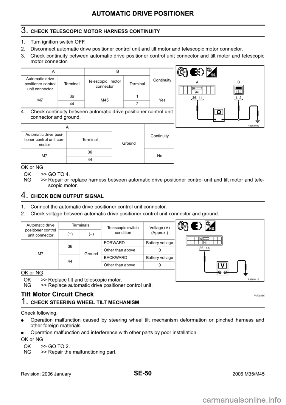
3. CHECK TELESCOPIC MOTOR HARNESS CONTINUITY
1. Turn ignition switch OFF.
2. Disconnect automatic drive positioner control unit and tilt motor and telescopic motor connector.
3. Check continuity between automatic drive positioner control unit connector and tilt motor and telescopic
motor connector.
4. Check continuity between automatic drive positioner control unit
connector and ground.
OK or NG
OK >> GO TO 4.
NG >> Repair or replace harness between automatic drive positioner control unit and tilt motor and tele-
scopic motor.
4. CHECK BCM OUTPUT SIGNAL
1. Connect the automatic drive positioner control unit connector.
2. Check voltage between automatic drive positioner control unit connector and ground.
OK or NG
OK >> Replace tilt and telescopic motor.
NG >> Replace automatic drive positioner control unit.
Tilt Motor Circuit CheckNIS0026C
1. CHECK STEERING WHEEL TILT MECHANISM
Check following.
Operation malfunction caused by steering wheel tilt mechanism deformation or pinched harness and
other foreign materials
Operation malfunction and interference with other parts by poor installation
OK or NG
OK >> GO TO 2.
NG >> Repair the malfunctioning part.
AB
Continuity Automatic drive
positioner control
unit connectorTe r m i n a lTelescopic motor
connectorTerminal
M736
M451
Ye s
44 2
A
GroundContinuity Automatic drive posi-
tioner control unit con-
nectorTerminal
M736
No
44
PIIB6140E
Automatic drive
positioner control
unit connectorTerminals
Telescopic switch
conditionVoltage (V)
(Approx.)
(+) (–)
M736
GroundFORWARD Battery voltage
Other than above 0
44BACKWARD Battery voltage
Other than above 0
PIIB6141E
Page 5364 of 5621

PRECAUTIONS
SRS-3
C
D
E
F
G
I
J
K
L
MA
B
SRS
Revision: 2006 January2006 M35/M45
PRECAUTIONSPFP:00001
Precautions for Supplemental Restraint System (SRS) “AIR BAG” and “SEAT
BELT PRE-TENSIONER”
NHS0008O
The Supplemental Restraint System such as “AIR BAG” and “SEAT BELT PRE-TENSIONER”, used along
with a front seat belt, helps to reduce the risk or severity of injury to the driver and front passenger for certain
types of collision. This system includes seat belt switch inputs and dual stage front air bag modules. The SRS
system uses the seat belt switches to determine the front air bag deployment, and may only deploy one front
air bag, depending on the severity of a collision and whether the front occupants are belted or unbelted.
Information necessary to service the system safely is included in the SRS and SB section of this Service Man-
ual.
WAR NING :
To avoid rendering the SRS inoperative, which could increase the risk of personal injury or death
in the event of a collision which would result in air bag inflation, all maintenance must be per-
formed by an authorized NISSAN/INFINITI dealer.
Improper maintenance, including incorrect removal and installation of the SRS, can lead to per-
sonal injury caused by unintentional activation of the system. For removal of Spiral Cable and Air
Bag Module, see the SRS section.
Do not use electrical test equipment on any circuit related to the SRS unless instructed to in this
Service Manual. SRS wiring harnesses can be identified by yellow and/or orange harnesses or
harness connectors.
Precautions for SRS “AIR BAG” and “SEAT BELT PRE-TENSIONER” ServiceNHS0008P
Do not use electrical test equipment to check SRS circuits unless instructed to in this Service Manual.
Before servicing the SRS, turn ignition switch OFF, disconnect both battery cables and wait at least 3 min-
utes.
For approximately 3 minutes after the cables are removed, it is still possible for the air bag and seat belt
pre-tensioner to deploy. Therefore, do not work on any SRS connectors or wires until at least 3 minutes
have passed.
Diagnosis sensor unit must always be installed with their arrow marks “” pointing towards the front of the
vehicle for proper operation. Also check diagnosis sensor unit for cracks, deformities or rust before instal-
lation and replace as required.
The spiral cable must be aligned with the neutral position since its rotations are limited. Do not turn steer-
ing wheel and column after removal of steering gear.
Handle air bag module carefully. Always place driver and front passenger air bag modules with the pad
side facing upward and seat mounted front side air bag module standing with the stud bolt side facing
down.
Conduct self-diagnosis to check entire SRS for proper function after replacing any components.
After air bag inflates, the front instrument panel assembly should be replaced if damaged.
Always replace instrument panel pad following front passenger air bag deployment.
Occupant Classification System PrecautionNHS0008Q
Replace occupant classification system control unit and passenger front seat cushion as an assembly.
Refer to SE-165, "
Passenger's Seat Components" .
Page 5400 of 5621

DRIVER AIR BAG MODULE
SRS-39
C
D
E
F
G
I
J
K
L
MA
B
SRS
Revision: 2006 January2006 M35/M45
3. Remove the screws then remove the steering switch.
INSTALLATION
Install in the reverse order of removal.
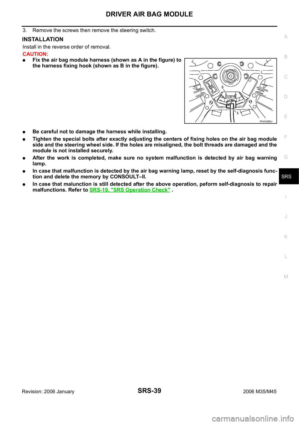
CAUTION:
Fix the air bag module harness (shown as A in the figure) to
the harness fixing hook (shown as B in the figure).
Be careful not to damage the harness while installing.
Tighten the special bolts after exactly adjusting the centers of fixing holes on the air bag module
side and the steering wheel side. If the holes are misaligned, the bolt threads are damaged and the
module is not installed securely.
After the work is completed, make sure no system malfunction is detected by air bag warning
lamp.
In case that malfunction is detected by the air bag warning lamp, reset by the self-diagnosis func-
tion and delete the memory by CONSOULT–II.
In case that malunction is still detected after the above operation, peform self-diagnosis to repair
malfunctions. Refer to SRS-19, "
SRS Operation Check" .
PHIA0885J
Page 5401 of 5621

SRS-40
SPIRAL CABLE
Revision: 2006 January2006 M35/M45
SPIRAL CABLEPFP:25554
Removal and InstallationNHS0009D
REMOVAL
CAUTION:
Before servicing, turn ignition switch OFF, disconnect both battery terminal and wait at least 3
minutes.
Do not use air tools or electric tools for servicing.
Do not disassemble the spiral cable.
Do not arrow oil, grease, detergent or water to come in contact with the spiral cable.
Do not make an impact to the spiral cable by dropping etc. Replace the spiral cable if it has been
dropped or sustained an impact.
1. Remove the air bag module. Refer to SRS-38, "
Removal and Installation" .
2. Remove the steering wheel. Refer to PS-12, "
Removal and Installation" .
3. Remove the column cover.
4. Remove the wiper washer switch, then remove light and turn signal switch from the spiral cable.
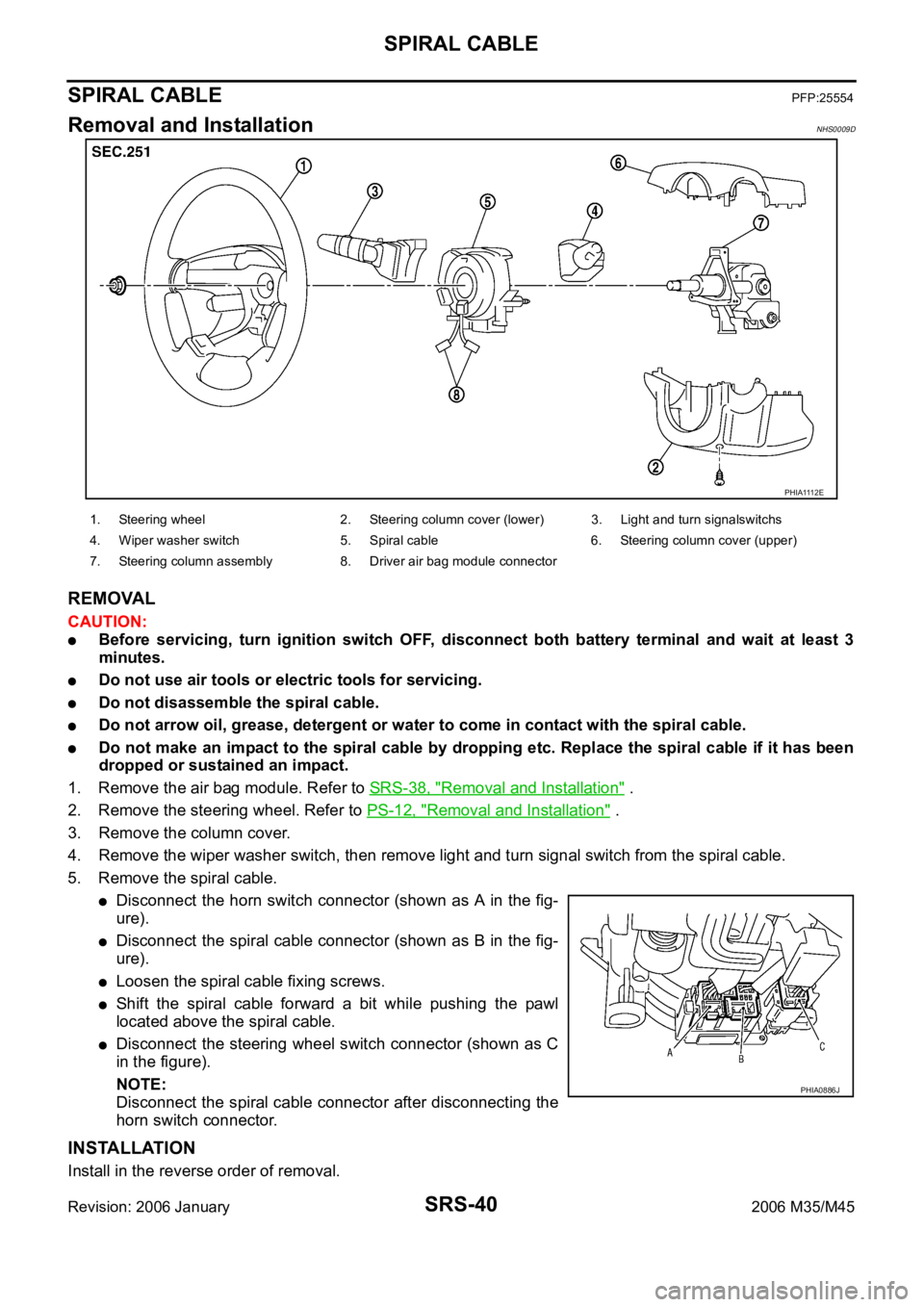
5. Remove the spiral cable.
Disconnect the horn switch connector (shown as A in the fig-
ure).
Disconnect the spiral cable connector (shown as B in the fig-
ure).
Loosen the spiral cable fixing screws.
Shift the spiral cable forward a bit while pushing the pawl
located above the spiral cable.
Disconnect the steering wheel switch connector (shown as C
in the figure).
NOTE:
Disconnect the spiral cable connector after disconnecting the
horn switch connector.
INSTALLATION
Install in the reverse order of removal.
PHIA1112E
1. Steering wheel 2. Steering column cover (lower) 3. Light and turn signalswitchs
4. Wiper washer switch 5. Spiral cable 6. Steering column cover (upper)
7. Steering column assembly 8. Driver air bag module connector
PHIA0886J