2006 INFINITI M35 torque
[x] Cancel search: torquePage 5130 of 5621
SEAT BELTS
SB-31
C
D
E
F
G
I
J
K
L
MA
B
SB
Revision: 2006 January2006 M35/M45
2. Remove the shoulder anchor.
Remove the center pillar lower and upper garnishes, refer to EI-37, "BODY SIDE TRIM" .
Remove the fixing anchor nut of the shoulder anchor.
3. Remove the seat bert assembly.
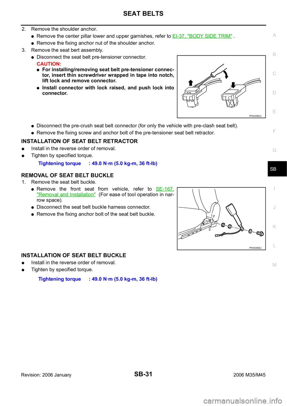
Disconnect the seat belt pre-tensioner connector.
CAUTION:
For installing/removing seat belt pre-tensioner connec-
tor, insert thin screwdriver wrapped in tape into notch,
lift lock and remove connector.
Install connector with lock raised, and push lock into
connector.
Disconnect the pre-crush seat belt connector (for only the vehicle with pre-clash seat belt).
Remove the fixing screw and anchor bolt of the pre-tensioner seat belt retractor.
INSTALLATION OF SEAT BELT RETRACTOR
Install in the reverse order of removal.
Tighten by specified torque.
REMOVAL OF SEAT BELT BUCKLE
1. Remove the seat belt buckle.
Remove the front seat from vehicle, refer to SE-167,
"Removal and Installation" (For ease of tool operation in nar-
row space).
Disconnect the seat belt buckle harness connector.
Remove the fixing anchor bolt of the seat belt buckle.
INSTALLATION OF SEAT BELT BUCKLE
Install in the reverse order of removal.
Tighten by specified torque.
PHIA0953J
Tightening torque : 49.0 Nꞏm (5.0 kg-m, 36 ft-lb)
PHIA0926J
Tightening torque : 49.0 Nꞏm (5.0 kg-m, 36 ft-lb)
Page 5131 of 5621
SB-32
SEAT BELTS
Revision: 2006 January2006 M35/M45
Removal and Installation of Rear Seat Belt NHS0008K
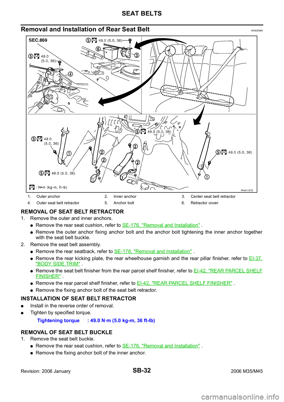
REMOVAL OF SEAT BELT RETRACTOR
1. Remove the outer and inner anchors.
Remove the rear seat cushion, refer to SE-176, "Removal and Installation" .
Remove the outer anchor fixing anchor bolt and the anchor bolt tightening the inner anchor together
with the seat belt buckle.
2. Remove the seat belt assembly.
Remove the rear seatback, refer to SE-176, "Removal and Installation" .
Remove the rear kicking plate, the rear wheelhouse garnish and the rear pillar finisher, refer to EI-37,
"BODY SIDE TRIM" .
Remove the seat belt finisher from the rear parcel shelf finisher, refer to EI-42, "REAR PARCEL SHELF
FINISHER" .
Remove the rear parcel shelf finisher, refer to EI-42, "REAR PARCEL SHELF FINISHER" .
Remove the fixing anchor bolt of the seat belt retractor.
INSTALLATION OF SEAT BELT RETRACTOR
Install in the reverse order of removal.
Tighten by specified torque.
REMOVAL OF SEAT BELT BUCKLE
1. Remove the seat belt buckle.
Remove the rear seat cushion, refer to SE-176, "Removal and Installation" .
Remove the fixing anchor bolt of the inner anchor.
1. Outer anchor 2. Inner anchor 3. Center seat belt retractor
4. Outer seat belt retractor 5. Anchor bolt 6. Retractor cover
PHIA1107E
Tightening torque : 49.0 Nꞏm (5.0 kg-m, 36 ft-lb)
Page 5132 of 5621
SEAT BELTS
SB-33
C
D
E
F
G
I
J
K
L
MA
B
SB
Revision: 2006 January2006 M35/M45
INSTALLATION OF SEAT BELT BUCKLE
Install in the reverse order of removal.
Tighten by specified torque.
Seat Belt InspectionNHS0008L
AFTER A COLLISION
WAR NING :
Inspect all seat belt assemblies including retractors and attaching hardware after any collision.
NISSAN / INFINITI recommends that all seat belt assemblies in use during a collision be replaced
unless the collision was minor and the belts show no damage and continue to operate properly. Fail-
ure to do so could result in serious personal injury in an accident. Seat belt assemblies not in use dur-
ing a collision should also be replaced if either damage or improper operation is noted. Seat belt pre-
tensioned should be replaced even if the seat belts are not in use during a frontal collision in which
the air bags are deployed.
Replace any seat belt assembly (including anchor bolts) if:
The seat belt was in use at the time of a collision (except for minor collisions and the belts, retractors and
buckles show no damage and continue to operate properly).
The seat belt was damaged in an accident. (i.e. torn webbing, bent retractor or guide, etc.)
The seat belt attaching point was damaged in an accident. Inspect the seat belt attaching area for damage
or distortion and repair as necessary before installing a new seat belt assembly.
Anchor bolts are deformed or worn out.
The seat belt pre-tensioner should be replaced even if the seat belts are not in use during the collision in
which the air bags are deployed.
PRELIMINARY CHECKS
1. Check the seat belt warning lamp/chime for proper operation as follows:
a. Switch ignition ON. The seat belt warning lamp should illuminate. Also, the seat belt warning chime should
sound for about six seconds.
b. Fasten driver's seat belt. The seat belt warning lamp should go out and the chime (if sounding) should
stop.
2. If the air bag warning lamp is blinking, conduct self-diagnosis using CONSULT-II, and air bag warning
lamp. Refer to SRS-19, "
SRS Operation Check" .
3. Check that the seat belt retractor, seat belt anchor and buckle bolts are securely attached.
4. Check the shoulder seat belt guide and shoulder belt height adjuster for front seats. Ensure guide swivels
freely and that webbing lays flat and does not bind in guide. Ensure height adjuster operates properly and
holds securely.
5. Check retractor operation:
a. Fully extend the seat belt webbing and check for twists, tears or other damage.
b. Allow the seat belt to retract. Ensure that webbing returns smoothly and completely into the retractor. If
the seat belt does not return smoothly, wipe the inside of the loops with a clean paper cloth. Because dirt
built up in the loops of the upper anchors can cause the seat belts to retract slowly.
c. Fasten the seat belt. Check the seat belt returns smoothly and completely to the retractor. If the webbing
does not return smoothly, the cause may be an accumulation of dust or dirt. Use the “SEAT BELT TAPE
SET” and perform the following steps.
Inspect the front seat belt though-anchor
1. Pull the seat belt out to a length of 500 mm (19.69 in) or more.
2. Use a clip or other device to the fix the seat belt at the center pillar webbing opening.
3. Pass a thin wire though the though-anchor webbing opening. Hold both ends of the wire and pull it
tantly while moving it up and down several times along the webbing opening surface to move matter
stuck there.
4. Any dirt that can not be removed with the wire can be removed by cleaning the opening with a clean
cloth.
5. Apply tape at the point where the webbing contacts the though-anchor webbing opening. Tightening torque : 49.0 Nꞏm (5.0 kg-m, 36 ft-lb)
Page 5135 of 5621
SB-36
LATCH (LOWER ANCHORS AND TETHER FOR CHILDREN) SYSTEM
Revision: 2006 January2006 M35/M45
LATCH (LOWER ANCHORS AND TETHER FOR CHILDREN) SYSTEMPFP:75466
Removal and InstallationNHS0008M
CAUTION:
Replace anchor bolts if they are deformed or worn out.
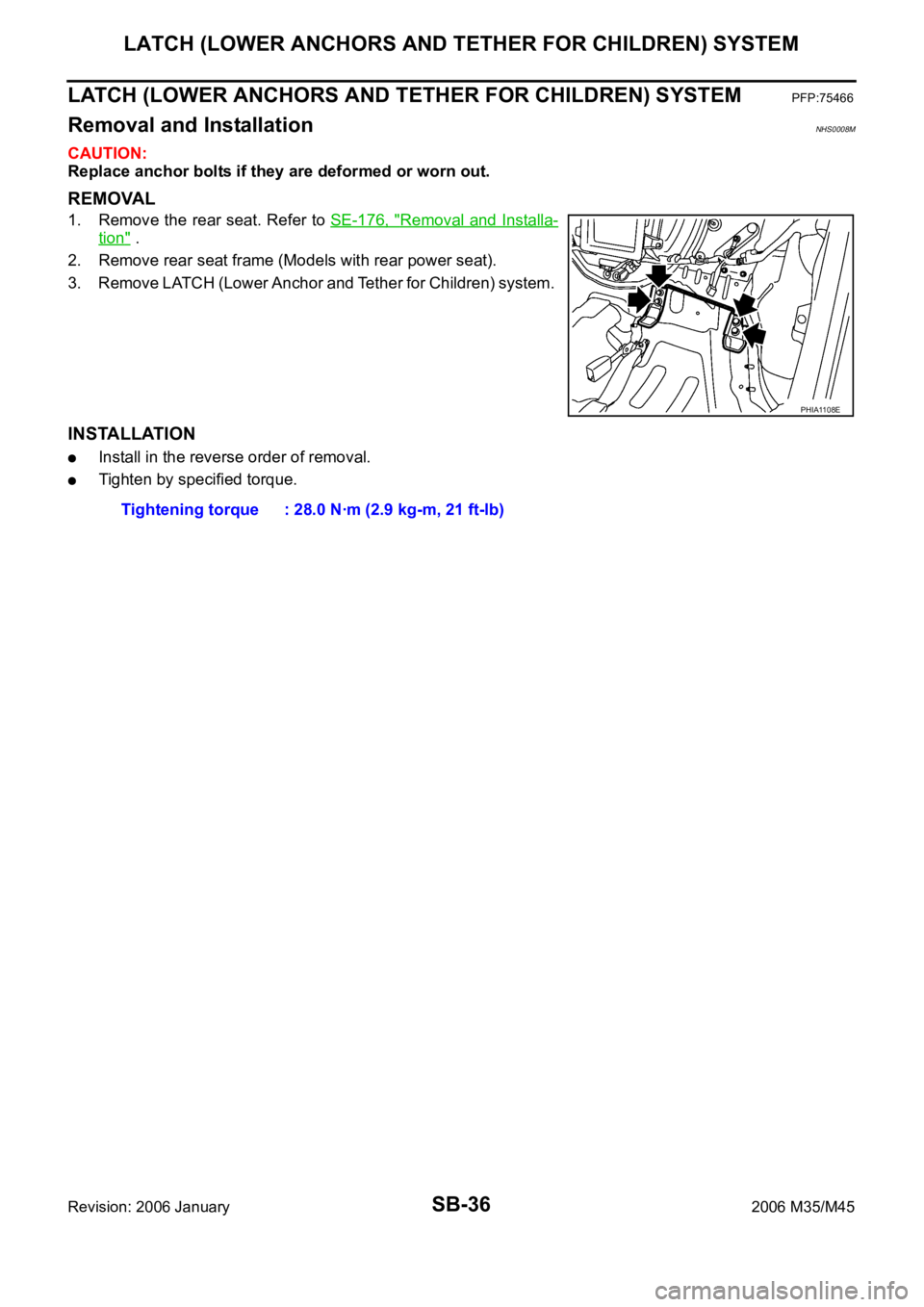
REMOVAL
1. Remove the rear seat. Refer to SE-176, "Removal and Installa-
tion" .
2. Remove rear seat frame (Models with rear power seat).
3. Remove LATCH (Lower Anchor and Tether for Children) system.
INSTALLATION
Install in the reverse order of removal.
Tighten by specified torque.
PHIA1108E
Tightening torque : 28.0 Nꞏm (2.9 kg-m, 21 ft-lb)
Page 5136 of 5621
TOP TETHER STRAP CHILD RESTRAINT
SB-37
C
D
E
F
G
I
J
K
L
MA
B
SB
Revision: 2006 January2006 M35/M45
TOP TETHER STRAP CHILD RESTRAINTPFP:88000
Removal and InstallationNHS0008N
CAUTION:
Replace anchor bolts if they are deformed or worn out.
REMOVAL
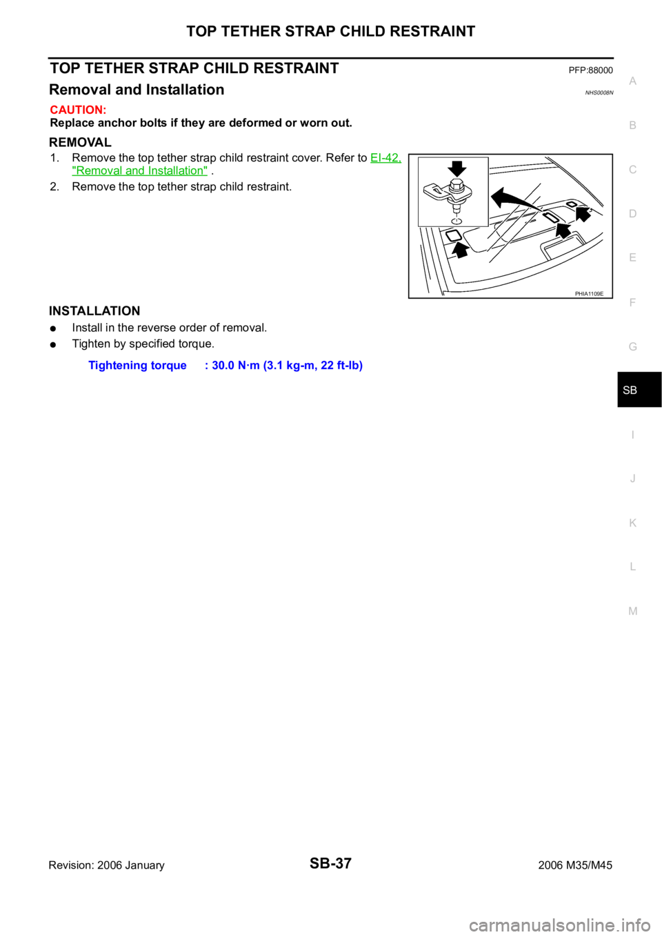
1. Remove the top tether strap child restraint cover. Refer to EI-42,
"Removal and Installation" .
2. Remove the top tether strap child restraint.
INSTALLATION
Install in the reverse order of removal.
Tighten by specified torque.
PHIA1109E
Tightening torque : 30.0 Nꞏm (3.1 kg-m, 22 ft-lb)
Page 5184 of 5621
PRECAUTIONS
SE-3
C
D
E
F
G
H
J
K
L
MA
B
SE
Revision: 2006 January2006 M35/M45
PRECAUTIONSPFP:00001
Precautions for Supplemental Restraint System (SRS) “AIR BAG” and “SEAT
BELT PRE-TENSIONER”
NIS0025I
The Supplemental Restraint System such as “AIR BAG” and “SEAT BELT PRE-TENSIONER”, used along
with a front seat belt, helps to reduce the risk or severity of injury to the driver and front passenger for certain
types of collision. This system includes seat belt switch inputs and dual stage front air bag modules. The SRS
system uses the seat belt switches to determine the front air bag deployment, and may only deploy one front
air bag, depending on the severity of a collision and whether the front occupants are belted or unbelted.
Information necessary to service the system safely is included in the SRS and SB section of this Service Man-
ual.
WAR NING :
To avoid rendering the SRS inoperative, which could increase the risk of personal injury or death
in the event of a collision which would result in air bag inflation, all maintenance must be per-
formed by an authorized NISSAN/INFINITI dealer.
Improper maintenance, including incorrect removal and installation of the SRS, can lead to per-
sonal injury caused by unintentional activation of the system. For removal of Spiral Cable and Air
Bag Module, see the SRS section.
Do not use electrical test equipment on any circuit related to the SRS unless instructed to in this
Service Manual. SRS wiring harnesses can be identified by yellow and/or orange harnesses or
harness connectors.
Service NoticeNIS0025J
When removing or installing various parts, place a cloth or padding onto the vehicle body to prevent
scratches.
Handle trim, molding, instruments, grille, etc. carefully during removing or installing. Be careful not to oil or
damage them.
Apply sealing compound where necessary when installing parts.
When applying sealing compound, be careful that the sealing compound does not protrude from parts.
When replacing any metal parts (for example body outer panel, members, etc.), be sure to take rust pre-
vention measures.
Precautions for WorkNIS0025K
When removing or disassembling each component, be careful not to damage or deform it. If a component
may be subject to interference, be sure to protect it with a shop cloth.
When removing (disengaging) components with a screwdriver or similar tool, be sure to wrap the compo-
nent with a shop cloth or vinyl tape to protect it.
Protect the removed parts with a shop cloth and keep them.
Replace a deformed or damaged clip.
If a part is specified as a non-reusable part, always replace it with new one.
Be sure to tighten bolts and nuts securely to the specified torque.
After re-installation is completed, be sure to check that each part works normally.
Follow the steps below to clean components.
–Water soluble foul: Dip a soft cloth into lukewarm water, and wring the water out of the cloth to wipe the
fouled area.
Then rub with a soft and dry cloth.
–Oily foul: Dip a soft cloth into lukewarm water with mild detergent (concentration: within 2 to 3%), and wipe
the fouled area.
Then dip a cloth into fresh water, and wring the water out of the cloth to wipe the detergent off. Then rub
with a soft and dry cloth.
Do not use organic solvent such as thinner, benzene, alcohol, and gasoline.
For genuine leather seats, use a genuine leather seat cleaner.
Page 5426 of 5621
![INFINITI M35 2006 Factory Service Manual TROUBLE DIAGNOSIS
STC-11
[EPS]
C
D
E
F
H
I
J
K
L
MA
B
STC
Revision: 2006 January2006 M35/M45
4. CHECK POWER STEERING SOLENOID VALVE POWER SUPPLY CIRCUIT
Check continuity between power steering co INFINITI M35 2006 Factory Service Manual TROUBLE DIAGNOSIS
STC-11
[EPS]
C
D
E
F
H
I
J
K
L
MA
B
STC
Revision: 2006 January2006 M35/M45
4. CHECK POWER STEERING SOLENOID VALVE POWER SUPPLY CIRCUIT
Check continuity between power steering co](/manual-img/42/57023/w960_57023-5425.png)
TROUBLE DIAGNOSIS
STC-11
[EPS]
C
D
E
F
H
I
J
K
L
MA
B
STC
Revision: 2006 January2006 M35/M45
4. CHECK POWER STEERING SOLENOID VALVE POWER SUPPLY CIRCUIT
Check continuity between power steering control unit harness con-
nector M8 and power steering solenoid valve harness connector F25
(VQ35DE), E211 (VK45DE).
OK or NG
OK >> GO TO 5.
NG >> Open or short in harness. Repair or replace any inoper-
ative parts.
5. CHECK POWER STEERING SOLENOID VALVE GROUND CIRCUIT
Check continuity between power steering solenoid valve harness
connector F25 (VQ35DE), E211 (VK45DE) and ground.
OK or NG
OK >> GO TO 6.
NG >> Open or short in harness. Repair or replace any inoper-
ative parts.
6. CHECK POWER STEERING SOLENOID VALVE
Apply voltage power steering solenoid valve connector, and then
make sure that the operating sound (clicking sound) is heard.
OK or NG
OK >> Perform steering turning torque inspection. Refer to PS-
10, "CHECKING STEERING WHEEL TURNING
FORCE" .
NG >> Power steering solenoid valve is inoperative. Replace.
Power steering control unit Power steering solenoid valve Continuity
Terminal 7 Terminal 1 Yes
SGIA1235E
Terminal 2 – Ground : Continuity exist.
SGIA1236E
Terminal 1 (+) - 2 (–) : Operating sound is heard.
SGIA1284E
Page 5428 of 5621
![INFINITI M35 2006 Factory Service Manual REAR ACTIVE STEER
STC-13
[RAS]
C
D
E
F
H
I
J
K
L
MA
B
STC
Revision: 2006 January2006 M35/M45
[RAS]REAR ACTIVE STEERPFP:55705
Removal and InstallationNGS000E5
COMPONENTS
REMOVAL
1. Remove coil spring. INFINITI M35 2006 Factory Service Manual REAR ACTIVE STEER
STC-13
[RAS]
C
D
E
F
H
I
J
K
L
MA
B
STC
Revision: 2006 January2006 M35/M45
[RAS]REAR ACTIVE STEERPFP:55705
Removal and InstallationNGS000E5
COMPONENTS
REMOVAL
1. Remove coil spring.](/manual-img/42/57023/w960_57023-5427.png)
REAR ACTIVE STEER
STC-13
[RAS]
C
D
E
F
H
I
J
K
L
MA
B
STC
Revision: 2006 January2006 M35/M45
[RAS]REAR ACTIVE STEERPFP:55705
Removal and InstallationNGS000E5
COMPONENTS
REMOVAL
1. Remove coil spring. Refer to RSU-16, "REAR LOWER LINK & COIL SPRING" .
2. Disconnect harness connector from RAS actuator assembly and rear suspension member.
3. Remove fixing bolts and nuts of RAS actuator assembly (1), and
then remove RAS actuator assembly (1) from rear suspension
member.
INSTALLATION
Installation is the reverse order of removal. For tightening torque, refer to STC-13, "COMPONENTS" .
When installing RAS actuator assembly to rear suspension member, check the mounting surfaces of RAS
actuator assembly and rear suspension member for oil, dirt, sand, or other foreign materials.
To perform the neutral position adjustment. Refer to STC-14, "Neutral Position Adjustment" .
1. Rear lower link 2. Decenter cam 3. RAS actuator assembly
Refer to GI-11, "
Components" , for the symbols in the figure.
SGIA1238E
SGIA1239E