Page 5522 of 5621

TRANSFER ASSEMBLY
TF-57
C
E
F
G
H
I
J
K
L
MA
B
TF
Revision: 2006 January2006 M35/M45
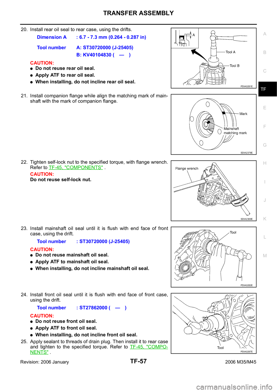
20. Install rear oil seal to rear case, using the drifts.
CAUTION:
Do not reuse rear oil seal.
Apply ATF to rear oil seal.
When installing, do not incline rear oil seal.
21. Install companion flange while align the matching mark of main-
shaft with the mark of companion flange.
22. Tighten self-lock nut to the specified torque, with flange wrench.
Refer to TF-45, "
COMPONENTS" .
CAUTION:
Do not reuse self-lock nut.
23. Install mainshaft oil seal until it is flush with end face of front
case, using the drift.
CAUTION:
Do not reuse mainshaft oil seal.
Apply ATF to mainshaft oil seal.
When installing, do not incline mainshaft oil seal.
24. Install front oil seal until it is flush with end face of front case,
using the drift.
CAUTION:
Do not reuse front oil seal.
Apply ATF to front oil seal.
When installing, do not incline front oil seal.
25. Apply sealant to threads of drain plug. Then install it to rear case
and tighten to the specified torque. Refer to TF-45, "
COMPO-
NENTS" . Dimension A : 6.7 - 7.3 mm (0.264 - 0.287 in)
Tool number A: ST30720000 (J-25405)
B: KV40104830 ( — )
PDIA0281E
SDIA2378E
SDIA2369E
Tool number : ST30720000 (J-25405)
PDIA0282E
Tool number : ST27862000 ( — )
PDIA0287E
Page 5523 of 5621
TF-58
TRANSFER ASSEMBLY
Revision: 2006 January2006 M35/M45
Use Genuine Silicone RTV or equivalent. Refer to GI-48, "Recommended Chemical Products and
Sealants" .
CAUTION:
Remove old sealant and oil adhering to threads.
26. Set gasket to filler plug. Install it to rear case and tighten to the specified torque. Refer to TF-45, "
COM-
PONENTS" .
CAUTION:
Do not reuse gasket.
After oil is filled, tighten filler plug to specified torque.
Page 5533 of 5621
WT-8
ROAD WHEEL TIRE ASSEMBLY
Revision: 2006 January2006 M35/M45
If either residual imbalance value exceeds 7 g (0.25 oz), repeat installation procedures.
RotationNES000JQ
Follow the maintenance schedule for tire rotation service intervals. Refer to MA-7, "PERIODIC MAINTE-
NANCE" .
Do not include the T-type spare tire when rotating the tires.
CAUTION:
When installing wheels, tighten them diagonally by divid-
ing the work two to three times in order to prevent the
wheels from developing any distortion.
Be careful not to tighten wheel nut at torque exceeding
the criteria for preventing strain of disc rotor.
Maximum allowable unbalanceDynamic (At rim flange) Less than 7 g (0.25 oz) (one side)
Static (At flange) Less than 14 g (0.49 oz)
Tightening torque
of wheel nut: 108 Nꞏm (11 kg-m, 80 ft-lb)
SMA829C
Page 5565 of 5621

WT-40
REMOVAL AND INSTALLATION
Revision: 2006 January2006 M35/M45
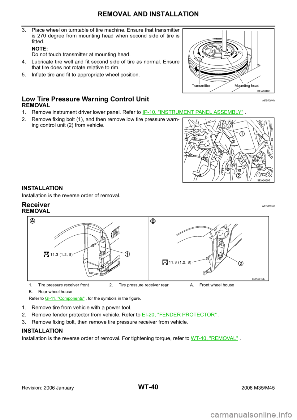
3. Place wheel on turntable of tire machine. Ensure that transmitter
is 270 degree from mounting head when second side of tire is
fitted.
NOTE:
Do not touch transmitter at mounting head.
4. Lubricate tire well and fit second side of tire as normal. Ensure
that tire does not rotate relative to rim.
5. Inflate tire and fit to appropriate wheel position.
Low Tire Pressure Warning Control UnitNES000KN
REMOVAL
1. Remove instrument driver lower panel. Refer to IP-10, "INSTRUMENT PANEL ASSEMBLY" .
2. Remove fixing bolt (1), and then remove low tire pressure warn-
ing control unit (2) from vehicle.
INSTALLATION
Installation is the reverse order of removal.
ReceiverNES000KO
REMOVAL
1. Remove tire from vehicle with a power tool.
2. Remove fender protector from vehicle. Refer to EI-20, "
FENDER PROTECTOR" .
3. Remove fixing bolt, then remove tire pressure receiver from vehicle.
INSTALLATION
Installation is the reverse order of removal. For tightening torque, refer to WT-40, "REMOVAL" .
SEIA0048E
SEIA0659E
1. Tire pressure receiver front 2. Tire pressure receiver rear A. Front wheel house
B. Rear wheel house
Refer to GI-11, "
Components" , for the symbols in the figure.
SEIA0649E
Page 5609 of 5621

WW-42
FRONT WIPER AND WASHER SYSTEM
Revision: 2006 January2006 M35/M45
Removal and Installation of Front Wiper Arms, Adjustment of Wiper Arms Stop
Location
NKS003WY
REMOVAL
1. Turn wiper switch ON to operate wiper motor, and then turn wiper switch OFF (auto stop).
2. Open hood, remove arm caps, and remove wiper arm nuts.
3. Raise wiper arm, and remove wiper arm from the vehicle.
INSTALLATION
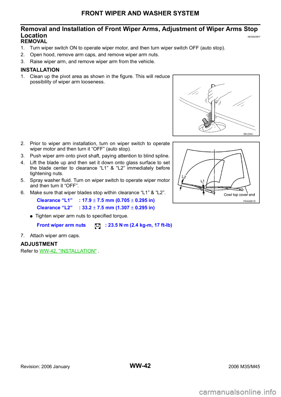
1. Clean up the pivot area as shown in the figure. This will reduce
possibility of wiper arm looseness.
2. Prior to wiper arm installation, turn on wiper switch to operate
wiper motor and then turn it “OFF” (auto stop).
3. Push wiper arm onto pivot shaft, paying attention to blind spline.
4. Lift the blade up and then set it down onto glass surface to set
the blade center to clearance “L1” & “L2” immediately before
tightening nuts.
5. Spray washer fluid. Turn on wiper switch to operate wiper motor
and then turn it “OFF”.
6. Make sure that wiper blades stop within clearance “L1” & “L2”.
Tighten wiper arm nuts to specified torque.
7. Attach wiper arm caps.
ADJUSTMENT
Refer to WW-42, "INSTALLATION" .
SEL024J
Clearance “L1” : 17.9 7.5 mm (0.705 0.295 in)
Clearance “L2” : 33.2
7.5 mm (1.307 0.295 in)
Front wiper arm nuts : 23.5 Nꞏm (2.4 kg-m, 17 ft-lb)
PKIA9951E
Page 5621 of 5621
WW-54
HORN
Revision: 2006 January2006 M35/M45
Removal and InstallationNKS003XF
REMOVAL
1. Remove front grille. Refer to EI-16, "FRONT GRILLE" .
2. Disconnect horn (HI) connectors.
3. Remove horn (HI) mounting bolt (A), and remove horn (HI) (1)
from vehicle.
4. Remove fender protector (front) LH to obtain work space between the fender protector and fender.
5. Disconnect horn (LO) connectors.
6. Remove horn (LO) mounting bolts (A), and remove horn (LO) (1)
from vehicle.
INSTALLATION
Tighten horn bolt to specified torque.
SKIB4266E
SKIB4267E
Horn mounting bolt :17.1 Nꞏm (1.7 kg-m, 13 ft-lb.)