Page 4867 of 5621
PG-40
PDU (POWER DISTRIBUTION UNIT)
Revision: 2006 January2006 M35/M45
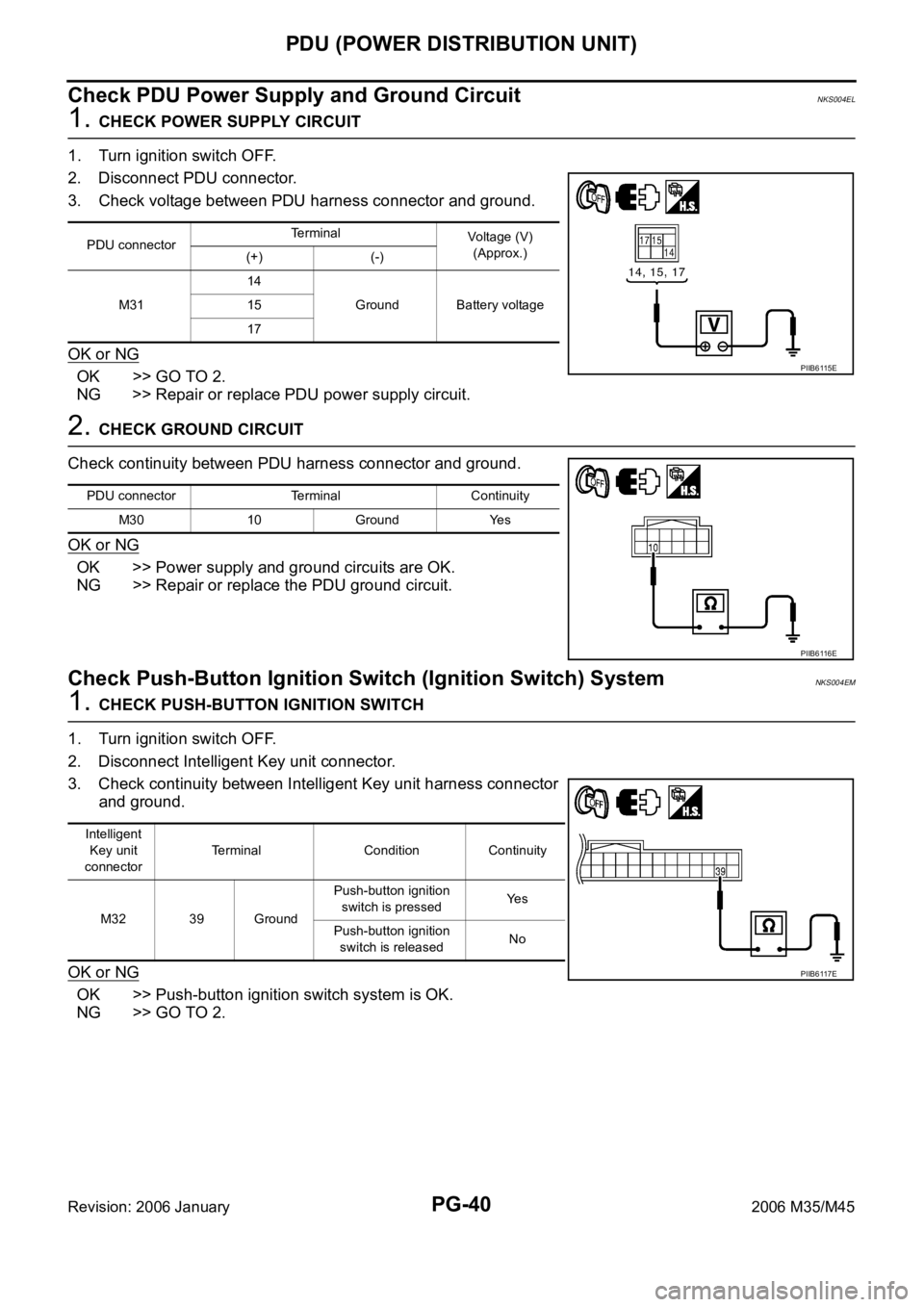
Check PDU Power Supply and Ground CircuitNKS004EL
1. CHECK POWER SUPPLY CIRCUIT
1. Turn ignition switch OFF.
2. Disconnect PDU connector.
3. Check voltage between PDU harness connector and ground.
OK or NG
OK >> GO TO 2.
NG >> Repair or replace PDU power supply circuit.
2. CHECK GROUND CIRCUIT
Check continuity between PDU harness connector and ground.
OK or NG
OK >> Power supply and ground circuits are OK.
NG >> Repair or replace the PDU ground circuit.
Check Push-Button Ignition Switch (Ignition Switch) SystemNKS004EM
1. CHECK PUSH-BUTTON IGNITION SWITCH
1. Turn ignition switch OFF.
2. Disconnect Intelligent Key unit connector.
3. Check continuity between Intelligent Key unit harness connector
and ground.
OK or NG
OK >> Push-button ignition switch system is OK.
NG >> GO TO 2.
PDU connectorTerminal
Voltage (V)
(Approx.)
(+) (-)
M3114
Ground Battery voltage 15
17
PIIB6115E
PDU connector Terminal Continuity
M30 10 Ground Yes
PIIB6116E
Intelligent
Key unit
connectorTerminal Condition Continuity
M32 39 GroundPush-button ignition
switch is pressedYe s
Push-button ignition
switch is releasedNo
PIIB6117E
Page 4868 of 5621
PDU (POWER DISTRIBUTION UNIT)
PG-41
C
D
E
F
G
H
I
J
L
MA
B
PG
Revision: 2006 January2006 M35/M45
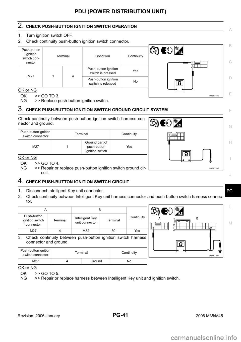
2. CHECK PUSH-BUTTON IGNITION SWITCH OPERATION
1. Turn ignition switch OFF.
2. Check continuity push-button ignition switch connector.
OK or NG
OK >> GO TO 3.
NG >> Replace push-button ignition switch.
3. CHECK PUSH-BUTTON IGNITION SWITCH GROUND CIRCUIT SYSTEM
Check continuity between push-button ignition switch harness con-
nector and ground.
OK or NG
OK >> GO TO 4.
NG >> Repair or replace push-button ignition switch ground cir-
cuit.
4. CHECK PUSH-BUTTON IGNITION SWITCH CIRCUIT
1. Disconnect Intelligent Key unit connector.
2. Check continuity between Intelligent Key unit harness connector and push-button switch harness connec-
tor.
3. Check continuity between push-button ignition switch harness
connector and ground.
OK or NG
OK >> GO TO 5.
NG >> Repair or replace harness between Intelligent Key unit and ignition switch.
Push-button
ignition
switch con-
nectorTerminal Condition Continuity
M27 1 4Push-button ignition
switch is pressedYe s
Push-button ignition
switch is releasedNo
PIIB6118E
Push-button ignition
switch connectorTerminal Continuity
M27 1Ground part of
push-button
ignition switchYe s
PIIB6120E
AB
Continuity Push-button
ignition switch
connectorTerminalIntelligent Key
unit connectorTerminal
M27 4 M32 39 Yes
Push-button ignition
switch connectorTerminal Continuity
M27 4 Ground No
PIIB6119E
Page 4869 of 5621
PG-42
PDU (POWER DISTRIBUTION UNIT)
Revision: 2006 January2006 M35/M45
Check Push-Button Ignition Switch (Indicator Circuit) SystemNKS004EN
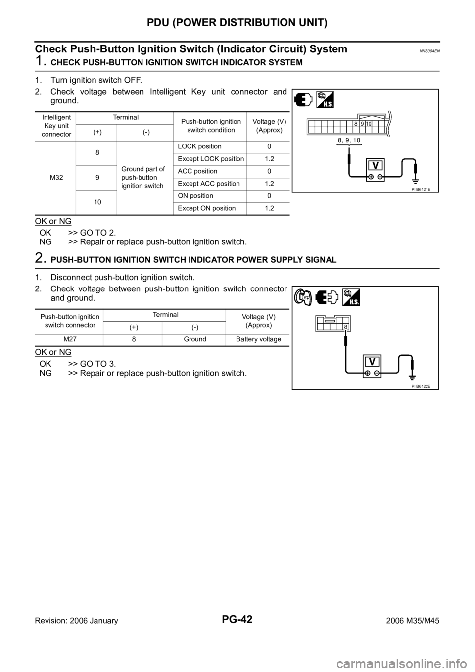
1. CHECK PUSH-BUTTON IGNITION SWITCH INDICATOR SYSTEM
1. Turn ignition switch OFF.
2. Check voltage between Intelligent Key unit connector and
ground.
OK or NG
OK >> GO TO 2.
NG >> Repair or replace push-button ignition switch.
2. PUSH-BUTTON IGNITION SWITCH INDICATOR POWER SUPPLY SIGNAL
1. Disconnect push-button ignition switch.
2. Check voltage between push-button ignition switch connector
and ground.
OK or NG
OK >> GO TO 3.
NG >> Repair or replace push-button ignition switch.
Intelligent
Key unit
connectorTe r m i n a l
Push-button ignition
switch conditionVoltage (V)
(Approx)
(+) (-)
M328
Ground part of
push-button
ignition switchLOCK position 0
Except LOCK position 1.2
9ACC position 0
Except ACC position 1.2
10ON position 0
Except ON position 1.2
PIIB6121E
Push-button ignition
switch connectorTerminal
Voltage (V)
(Approx)
(+) (-)
M27 8 Ground Battery voltage
PIIB6122E
Page 4870 of 5621
PDU (POWER DISTRIBUTION UNIT)
PG-43
C
D
E
F
G
H
I
J
L
MA
B
PG
Revision: 2006 January2006 M35/M45
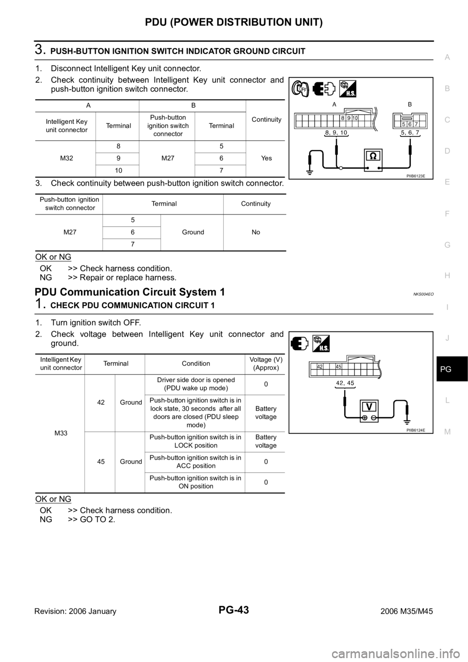
3. PUSH-BUTTON IGNITION SWITCH INDICATOR GROUND CIRCUIT
1. Disconnect Intelligent Key unit connector.
2. Check continuity between Intelligent Key unit connector and
push-button ignition switch connector.
3. Check continuity between push-button ignition switch connector.
OK or NG
OK >> Check harness condition.
NG >> Repair or replace harness.
PDU Communication Circuit System 1NKS004EO
1. CHECK PDU COMMUNICATION CIRCUIT 1
1. Turn ignition switch OFF.
2. Check voltage between Intelligent Key unit connector and
ground.
OK or NG
OK >> Check harness condition.
NG >> GO TO 2.
AB
Continuity
Intelligent Key
unit connectorTerminalPush-button
ignition switch
connectorTe r m i n a l
M328
M275
Ye s 96
10 7
P u s h - b u t t o n i g n i t i o n
switch connectorTerminal Continuity
M275
Ground No 6
7
PIIB6123E
Intelligent Key
unit connectorTerminal ConditionVoltage (V)
(Approx)
M3342 GroundDriver side door is opened
(PDU wake up mode)0
Push-button ignition switch is in
lock state, 30 seconds after all
doors are closed (PDU sleep
mode)Battery
voltage
45 GroundPush-button ignition switch is in
LOCK positionBattery
voltage
Push-button ignition switch is in
ACC position0
Push-button ignition switch is in
ON position0
PIIB6124E
Page 4871 of 5621
PG-44
PDU (POWER DISTRIBUTION UNIT)
Revision: 2006 January2006 M35/M45
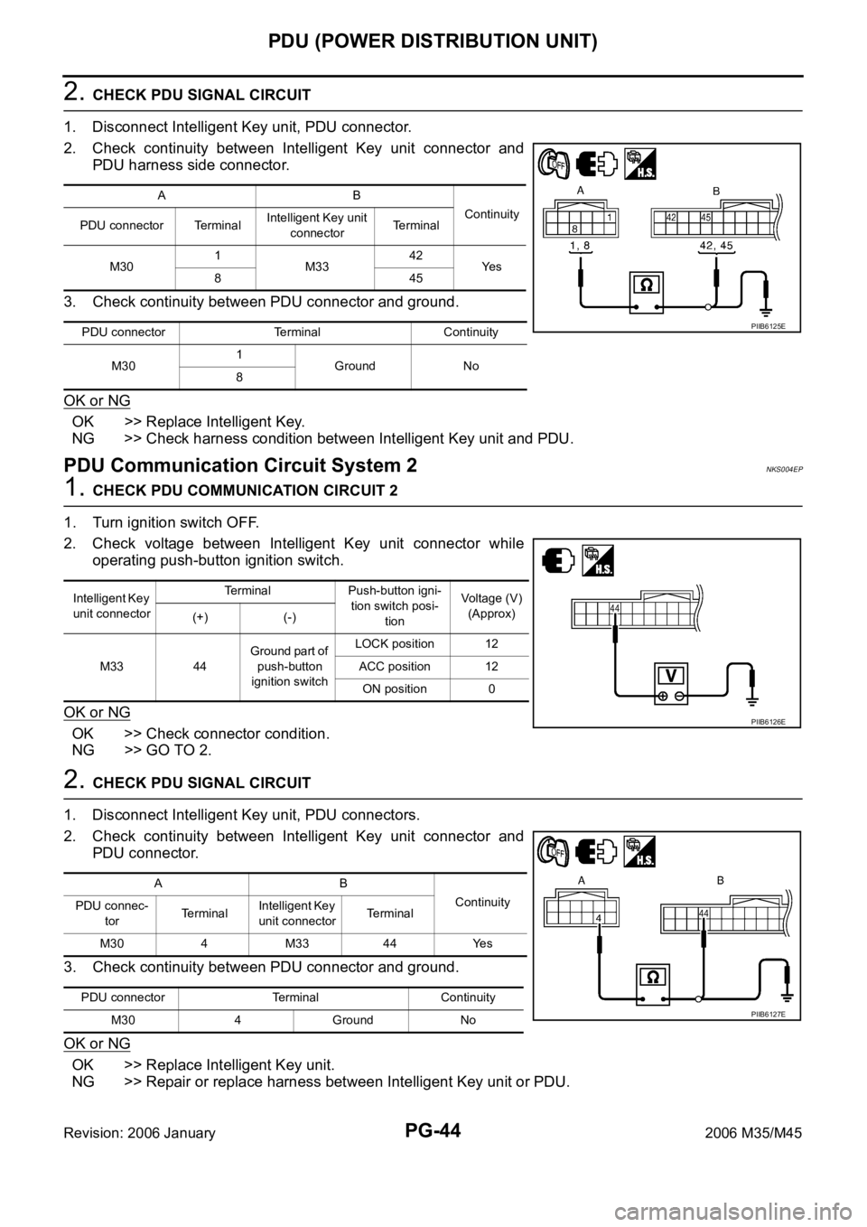
2. CHECK PDU SIGNAL CIRCUIT
1. Disconnect Intelligent Key unit, PDU connector.
2. Check continuity between Intelligent Key unit connector and
PDU harness side connector.
3. Check continuity between PDU connector and ground.
OK or NG
OK >> Replace Intelligent Key.
NG >> Check harness condition between Intelligent Key unit and PDU.
PDU Communication Circuit System 2NKS004EP
1. CHECK PDU COMMUNICATION CIRCUIT 2
1. Turn ignition switch OFF.
2. Check voltage between Intelligent Key unit connector while
operating push-button ignition switch.
OK or NG
OK >> Check connector condition.
NG >> GO TO 2.
2. CHECK PDU SIGNAL CIRCUIT
1. Disconnect Intelligent Key unit, PDU connectors.
2. Check continuity between Intelligent Key unit connector and
PDU connector.
3. Check continuity between PDU connector and ground.
OK or NG
OK >> Replace Intelligent Key unit.
NG >> Repair or replace harness between Intelligent Key unit or PDU.
AB
Continuity
PDU connector TerminalIntelligent Key unit
connectorTerminal
M301
M3342
Ye s
845
PDU connector Terminal Continuity
M301
Ground No
8
PIIB6125E
Intelligent Key
unit connectorTerminal Push-button igni-
tion switch posi-
tionVoltage (V)
(Approx)
(+) (-)
M33 44Ground part of
push-button
ignition switchLOCK position 12
ACC position 12
ON position 0
PIIB6126E
AB
Continuity
PDU connec-
torTerminalIntelligent Key
unit connectorTerminal
M30 4 M33 44 Yes
PDU connector Terminal Continuity
M30 4 Ground No
PIIB6127E
Page 4943 of 5621
PR-4
FRONT PROPELLER SHAFT
Revision: 2006 January2006 M35/M45
FRONT PROPELLER SHAFTPFP:37200
On-Vehicle InspectionNDS000EA
APPEARANCE AND NOISE INSPECTION
Check the propeller shaft tube surface for dents or cracks. If damaged, replace propeller shaft assembly.
PROPELLER SHAFT VIBRATION
If vibration is present at high speed, inspect propeller shaft runout first.
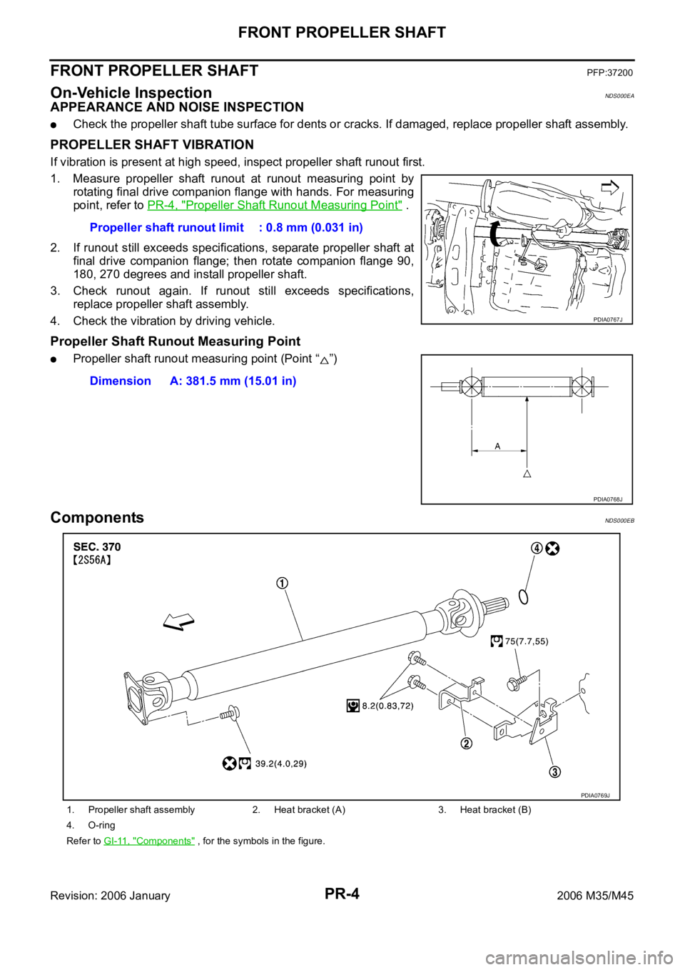
1. Measure propeller shaft runout at runout measuring point by
rotating final drive companion flange with hands. For measuring
point, refer to PR-4, "
Propeller Shaft Runout Measuring Point" .
2. If runout still exceeds specifications, separate propeller shaft at
final drive companion flange; then rotate companion flange 90,
180, 270 degrees and install propeller shaft.
3. Check runout again. If runout still exceeds specifications,
replace propeller shaft assembly.
4. Check the vibration by driving vehicle.
Propeller Shaft Runout Measuring Point
Propeller shaft runout measuring point (Point “ ”)
ComponentsNDS000EB
Propeller shaft runout limit : 0.8 mm (0.031 in)
PDIA0767J
Dimension A: 381.5 mm (15.01 in)
PDIA0768J
1. Propeller shaft assembly 2. Heat bracket (A) 3. Heat bracket (B)
4. O-ring
Refer to GI-11, "
Components" , for the symbols in the figure.
PDIA0769J
Page 4944 of 5621
FRONT PROPELLER SHAFT
PR-5
C
E
F
G
H
I
J
K
L
MA
B
PR
Revision: 2006 January2006 M35/M45
Removal and InstallationNDS000EC
REMOVAL
1. Remove engine undercover with a power tool.
2. If necessary, remove heat bracket.
3. Remove the three way catalyst (right bank) with a power tool. Refer to EX-3, "
EXHAUST SYSTEM" .
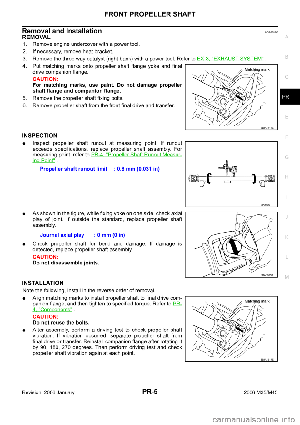
4. Put matching marks onto propeller shaft flange yoke and final
drive companion flange.
CAUTION:
For matching marks, use paint. Do not damage propeller
shaft flange and companion flange.
5. Remove the propeller shaft fixing bolts.
6. Remove propeller shaft from the front final drive and transfer.
INSPECTION
Inspect propeller shaft runout at measuring point. If runout
exceeds specifications, replace propeller shaft assembly. For
measuring point, refer to PR-4, "
Propeller Shaft Runout Measur-
ing Point" .
As shown in the figure, while fixing yoke on one side, check axial
play of joint. If outside the standard, replace propeller shaft
assembly.
Check propeller shaft for bend and damage. If damage is
detected, replace propeller shaft assembly.
CAUTION:
Do not disassemble joints.
INSTALLATION
Note the following, install in the reverse order of removal.
Align matching marks to install propeller shaft to final drive com-
panion flange, and then tighten to specified torque. Refer to PR-
4, "Components" .
CAUTION:
Do not reuse the bolts.
After assembly, perform a driving test to check propeller shaft
vibration. If vibration occurred, separate propeller shaft from
final drive or transfer. Reinstall companion flange after rotating it
by 90, 180, 270 degrees. Then perform driving test and check
propeller shaft vibration again at each point.
SDIA1517E
Propeller shaft runout limit : 0.8 mm (0.031 in)
SPD106
Journal axial play : 0 mm (0 in)
PDA0005D
SDIA1517E
Page 4945 of 5621
PR-6
REAR PROPELLER SHAFT
Revision: 2006 January2006 M35/M45
REAR PROPELLER SHAFTPFP:37000
On-Vehicle InspectionNDS000ED
APPEARANCE AND NOISE INSPECTION
Check the propeller shaft tube surface for dents or cracks. If damaged, replace propeller shaft assembly.
If center bearing is noisy or damaged, replace center bearing.
PROPELLER SHAFT VIBRATION
If vibration is present at high speed, inspect propeller shaft runout first.
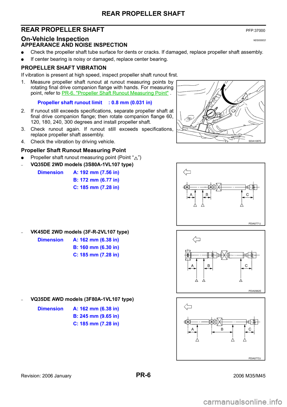
1. Measure propeller shaft runout at runout measuring points by
rotating final drive companion flange with hands. For measuring
point, refer to PR-6, "
Propeller Shaft Runout Measuring Point" .
2. If runout still exceeds specifications, separate propeller shaft at
final drive companion flange; then rotate companion flange 60,
120, 180, 240, 300 degrees and install propeller shaft.
3. Check runout again. If runout still exceeds specifications,
replace propeller shaft assembly.
4. Check the vibration by driving vehicle.
Propeller Shaft Runout Measuring Point
Propeller shaft runout measuring point (Point “ ”)
–VQ35DE 2WD models (3S80A-1VL107 type)
–VK45DE 2WD models (3F-R-2VL107 type)
–VQ35DE AWD models (3F80A-1VL107 type)Propeller shaft runout limit : 0.8 mm (0.031 in)
SDIA1087E
Dimension A: 192 mm (7.56 in)
B: 172 mm (6.77 in)
C: 185 mm (7.28 in)
PDIA0771J
Dimension A: 162 mm (6.38 in)
B: 160 mm (6.30 in)
C: 185 mm (7.28 in)
PDIA0962E
Dimension A: 162 mm (6.38 in)
B: 245 mm (9.65 in)
C: 185 mm (7.28 in)
PDIA0772J