2006 INFINITI M35 check
[x] Cancel search: checkPage 4964 of 5621
STEERING WHEEL
PS-11
C
D
E
F
H
I
J
K
L
MA
B
PS
Revision: 2006 January2006 M35/M45
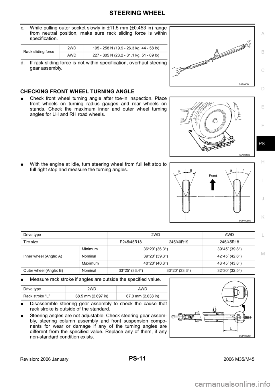
c. While pulling outer socket slowly in 11 . 5 m m (0.453 in) range
from neutral position, make sure rack sliding force is within
specification.
d. If rack sliding force is not within specification, overhaul steering
gear assembly.
CHECKING FRONT WHEEL TURNING ANGLE
Check front wheel turning angle after toe-in inspection. Place
front wheels on turning radius gauges and rear wheels on
stands. Check the maximum inner and outer wheel turning
angles for LH and RH road wheels.
With the engine at idle, turn steering wheel from full left stop to
full right stop and measure the turning angles.
Measure rack stroke if angles are outside the specified value.
Disassemble steering gear assembly to check the cause that
rack stroke is outside of the standard.
Steering angles are not adjustable. Check steering gear assem-
bly, steering column assembly and front suspension compo-
nents for wear or damage if any of the turning angles are
different from the specified value. Replace any of them, if any
non-standard condition exists.
Rack sliding force2WD 195 - 258 N (19.9 - 26.3 kg, 44 - 58 lb)
AWD 227 - 305 N (23.2 - 31.1 kg, 51 - 69 lb)
SST090B
FAA0016D
SGIA0055E
Drive type 2WD AWD
Tire size P245/45R18 245/40R19 245/45R18
Inner wheel (Angle: A)Minimum 36
20 (36.3)3945 (39.8)
Nominal 39
20 (39.3)4245 (42.8)
Maximum 40
20 (40.3)4345 (43.8)
Outer wheel (Angle: B) Nominal 33
25 (33.4)3320 (33.3)3230 (32.5)
Drive type 2WD AWD
Rack stroke “L” 68.5 mm (2.697 in) 67.0 mm (2.638 in)
SGIA0629J
Page 4967 of 5621
PS-14
STEERING COLUMN
Revision: 2006 January2006 M35/M45
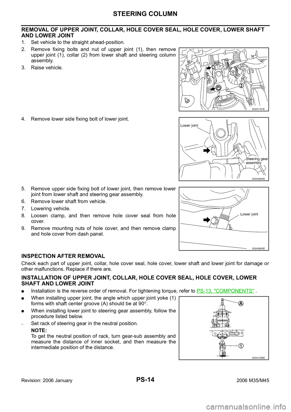
REMOVAL OF UPPER JOINT, COLLAR, HOLE COVER SEAL, HOLE COVER, LOWER SHAFT
AND LOWER JOINT
1. Set vehicle to the straight ahead-position.
2. Remove fixing bolts and nut of upper joint (1), then remove
upper joint (1), collar (2) from lower shaft and steering column
assembly.
3. Raise vehicle.
4. Remove lower side fixing bolt of lower joint.
5. Remove upper side fixing bolt of lower joint, then remove lower
joint from lower shaft and steering gear assembly.
6. Remove lower shaft from vehicle.
7. Lowering vehicle.
8. Loosen clamp, and then remove hole cover seal from hole
cover.
9. Remove mounting nuts of hole cover, and then remove clamp
and hole cover from dash panel.
INSPECTION AFTER REMOVAL
Check each part of upper joint, collar, hole cover seal, hole cover, lower shaft and lower joint for damage or
other malfunctions. Replace if there are.
INSTALLATION OF UPPER JOINT, COLLAR, HOLE COVER SEAL, HOLE COVER, LOWER
SHAFT AND LOWER JOINT
Installation is the reverse order of removal. For tightening torque, refer to PS-13, "COMPONENTS" .
When installing upper joint, the angle which upper joint yoke (1)
forms with shaft center groove (A) should be at 90
.
When installing lower joint to steering gear assembly, follow the
procedure listed below.
–Set rack of steering gear in the neutral position.
NOTE:
To get the neutral position of rack, turn gear-sub assembly and
measure the distance of inner socket, and then measure the
intermediate position of the distance.
SGIA1181E
SGIA0844E
SGIA0845E
SGIA1290E
Page 4969 of 5621
PS-16
STEERING COLUMN
Revision: 2006 January2006 M35/M45
INSPECTION AFTER REMOVAL
Check each part of steering column assembly for damage or other malfunctions. Replace if there are.
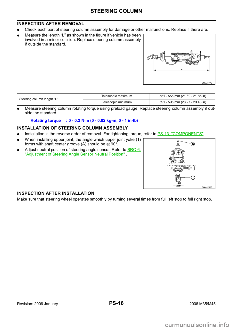
Measure the length “L” as shown in the figure if vehicle has been
involved in a minor collision. Replace steering column assembly
if outside the standard.
Measure steering column rotating torque using preload gauge. Replace steering column assembly if out-
side the standard.
INSTALLATION OF STEERING COLUMN ASSEMBLY
Installation is the reverse order of removal. For tightening torque, refer to PS-13, "COMPONENTS" .
When installing upper joint, the angle which upper joint yoke (1)
forms with shaft center groove (A) should be at 90
.
Adjust neutral position of steering angle sensor. Refer to BRC-6,
"Adjustment of Steering Angle Sensor Neutral Position" .
INSPECTION AFTER INSTALLATION
Make sure that steering wheel operates smoothly by turning several times from full left stop to full right stop.
SGIA1177E
Steering column length “L”Telescopic maximum 551 - 555 mm (21.69 - 21.85 in)
Telescopic minimum 591 - 595 mm (23.27 - 23.43 in)
Rotating torque : 0 - 0.2 Nꞏm (0 - 0.02 kg-m, 0 - 1 in-lb)
SGIA1290E
Page 4970 of 5621
STEERING COLUMN
PS-17
C
D
E
F
H
I
J
K
L
MA
B
PS
Revision: 2006 January2006 M35/M45
Disassembly and AssemblyNGS000DB
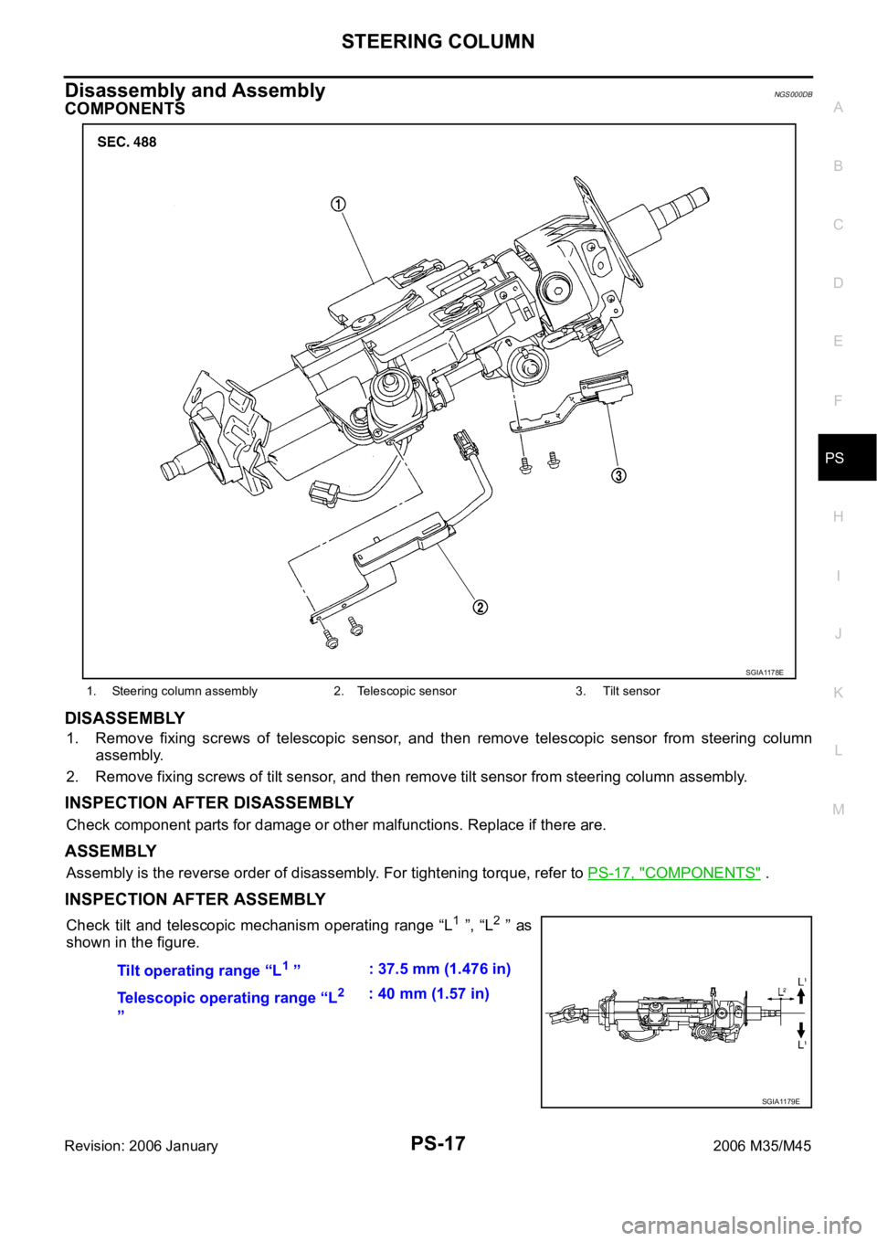
COMPONENTS
DISASSEMBLY
1. Remove fixing screws of telescopic sensor, and then remove telescopic sensor from steering column
assembly.
2. Remove fixing screws of tilt sensor, and then remove tilt sensor from steering column assembly.
INSPECTION AFTER DISASSEMBLY
Check component parts for damage or other malfunctions. Replace if there are.
ASSEMBLY
Assembly is the reverse order of disassembly. For tightening torque, refer to PS-17, "COMPONENTS" .
INSPECTION AFTER ASSEMBLY
Check tilt and telescopic mechanism operating range “L1 ”, “L2 ” as
shown in the figure.
1. Steering column assembly 2. Telescopic sensor 3. Tilt sensor
SGIA1178E
Tilt operating range “L1 ”: 37.5 mm (1.476 in)
Telescopic operating range “L
2
”: 40 mm (1.57 in)
SGIA1179E
Page 4972 of 5621
POWER STEERING GEAR
PS-19
C
D
E
F
H
I
J
K
L
MA
B
PS
Revision: 2006 January2006 M35/M45
8. Remove steering hydraulic piping bracket from front suspension member. Refer to PS-38, "HYDRAULIC
LINE" .
9. Remove EPS solenoid valve harness connector. Refer to PS-20, "
COMPONENTS" .
10. Remove rack stay (2WD) or front cross bar (AWD). Refer to FSU-8, "
Components" , FSU-25, "Compo-
nents" .
11. Remove mounting bolts and nuts of steering gear assembly, and then remove steering gear assembly
from vehicle.
INSTALLATION
Installation is the reverse order of removal. For tightening torque, refer to PS-18, "COMPONENTS" .
When installing lower joint to steering gear assembly, follow the procedure listed below.
–Set rack of steering gear in the neutral position.
NOTE:
To get the neutral position of rack, turn gear-sub assembly and measure the distance of inner socket, and
then measure the intermediate position of the distance.
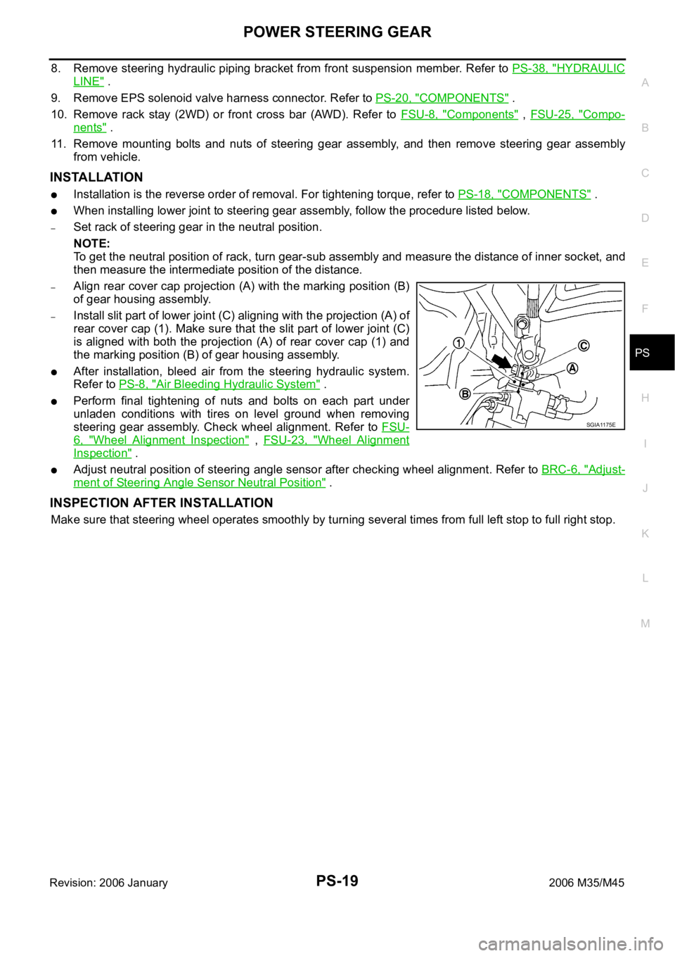
–Align rear cover cap projection (A) with the marking position (B)
of gear housing assembly.
–Install slit part of lower joint (C) aligning with the projection (A) of
rear cover cap (1). Make sure that the slit part of lower joint (C)
is aligned with both the projection (A) of rear cover cap (1) and
the marking position (B) of gear housing assembly.
After installation, bleed air from the steering hydraulic system.
Refer to PS-8, "
Air Bleeding Hydraulic System" .
Perform final tightening of nuts and bolts on each part under
unladen conditions with tires on level ground when removing
steering gear assembly. Check wheel alignment. Refer to FSU-
6, "Wheel Alignment Inspection" , FSU-23, "Wheel Alignment
Inspection" .
Adjust neutral position of steering angle sensor after checking wheel alignment. Refer to BRC-6, "Adjust-
ment of Steering Angle Sensor Neutral Position" .
INSPECTION AFTER INSTALLATION
Make sure that steering wheel operates smoothly by turning several times from full left stop to full right stop.
SGIA1175E
Page 4975 of 5621
PS-22
POWER STEERING GEAR
Revision: 2006 January2006 M35/M45
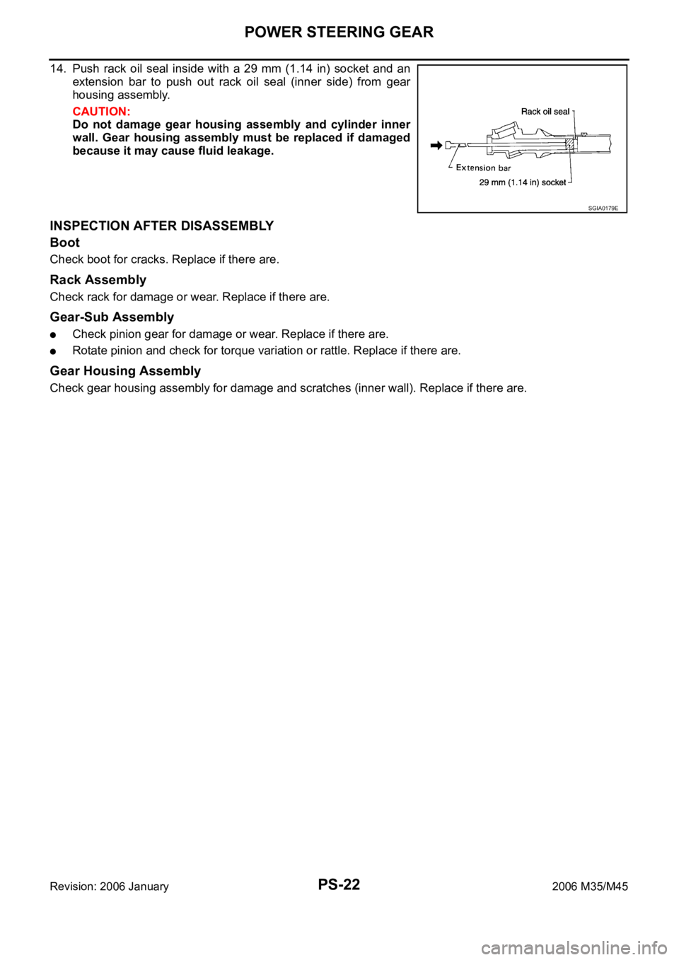
14. Push rack oil seal inside with a 29 mm (1.14 in) socket and an
extension bar to push out rack oil seal (inner side) from gear
housing assembly.
CAUTION:
Do not damage gear housing assembly and cylinder inner
wall. Gear housing assembly must be replaced if damaged
because it may cause fluid leakage.
INSPECTION AFTER DISASSEMBLY
Boot
Check boot for cracks. Replace if there are.
Rack Assembly
Check rack for damage or wear. Replace if there are.
Gear-Sub Assembly
Check pinion gear for damage or wear. Replace if there are.
Rotate pinion and check for torque variation or rattle. Replace if there are.
Gear Housing Assembly
Check gear housing assembly for damage and scratches (inner wall). Replace if there are.
SGIA0179E
Page 4981 of 5621
PS-28
POWER STEERING GEAR
Revision: 2006 January2006 M35/M45
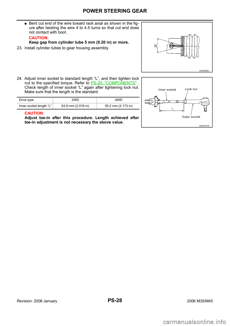
Bent cut end of the wire toward rack axial as shown in the fig-
ure after twisting the wire 4 to 4.5 turns so that cut end does
not contact with boot.
CAUTION:
Keep gap from cylinder tube 5 mm (0.20 in) or more.
23. Install cylinder tubes to gear housing assembly.
24. Adjust inner socket to standard length “L”, and then tighten lock
nut to the specified torque. Refer to PS-20, "
COMPONENTS" .
Check length of inner socket “L” again after tightening lock nut.
Make sure that the length is the standard.
CAUTION:
Adjust toe-in after this procedure. Length achieved after
toe-in adjustment is not necessary the above value.
SGIA0260J
Drive type 2WD AWD
Inner socket length “L” 63.9 mm (2.516 in) 55.2 mm (2.173 in)
SGIA0167E
Page 4982 of 5621
POWER STEERING OIL PUMP
PS-29
C
D
E
F
H
I
J
K
L
MA
B
PS
Revision: 2006 January2006 M35/M45
POWER STEERING OIL PUMPPFP:49110
On-Vehicle Inspection and ServiceNGS000DE
CHECKING RELIEF OIL PRESSURE
CAUTION:
Make sure that belt tension is normal before starting the following procedure.
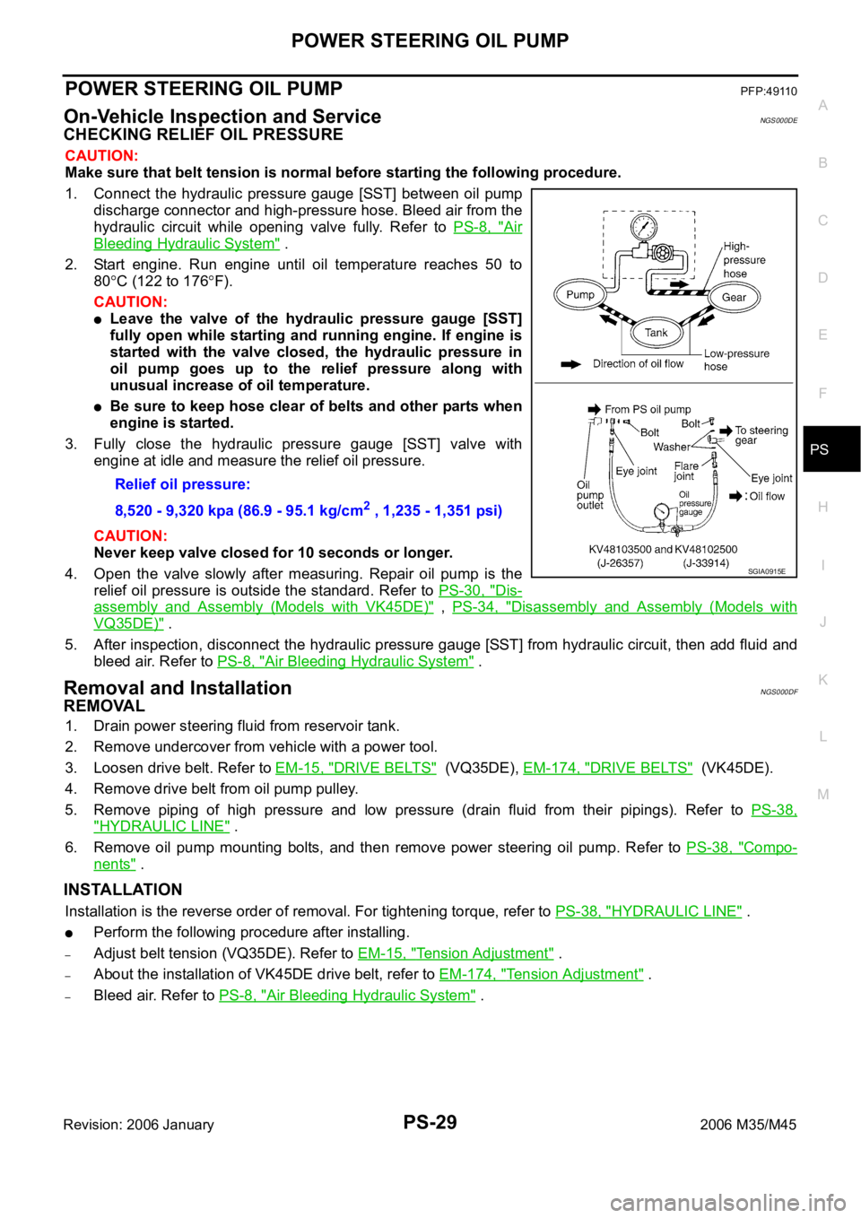
1. Connect the hydraulic pressure gauge [SST] between oil pump
discharge connector and high-pressure hose. Bleed air from the
hydraulic circuit while opening valve fully. Refer to PS-8, "
Air
Bleeding Hydraulic System" .
2. Start engine. Run engine until oil temperature reaches 50 to
80
C (122 to 176F).
CAUTION:
Leave the valve of the hydraulic pressure gauge [SST]
fully open while starting and running engine. If engine is
started with the valve closed, the hydraulic pressure in
oil pump goes up to the relief pressure along with
unusual increase of oil temperature.
Be sure to keep hose clear of belts and other parts when
engine is started.
3. Fully close the hydraulic pressure gauge [SST] valve with
engine at idle and measure the relief oil pressure.
CAUTION:
Never keep valve closed for 10 seconds or longer.
4. Open the valve slowly after measuring. Repair oil pump is the
relief oil pressure is outside the standard. Refer to PS-30, "
Dis-
assembly and Assembly (Models with VK45DE)" , PS-34, "Disassembly and Assembly (Models with
VQ35DE)" .
5. After inspection, disconnect the hydraulic pressure gauge [SST] from hydraulic circuit, then add fluid and
bleed air. Refer to PS-8, "
Air Bleeding Hydraulic System" .
Removal and InstallationNGS000DF
REMOVAL
1. Drain power steering fluid from reservoir tank.
2. Remove undercover from vehicle with a power tool.
3. Loosen drive belt. Refer to EM-15, "
DRIVE BELTS" (VQ35DE), EM-174, "DRIVE BELTS" (VK45DE).
4. Remove drive belt from oil pump pulley.
5. Remove piping of high pressure and low pressure (drain fluid from their pipings). Refer to PS-38,
"HYDRAULIC LINE" .
6. Remove oil pump mounting bolts, and then remove power steering oil pump. Refer to PS-38, "
Compo-
nents" .
INSTALLATION
Installation is the reverse order of removal. For tightening torque, refer to PS-38, "HYDRAULIC LINE" .
Perform the following procedure after installing.
–Adjust belt tension (VQ35DE). Refer to EM-15, "Tension Adjustment" .
–About the installation of VK45DE drive belt, refer to EM-174, "Tension Adjustment" .
–Bleed air. Refer to PS-8, "Air Bleeding Hydraulic System" . Relief oil pressure:
8,520 - 9,320 kpa (86.9 - 95.1 kg/cm
2 , 1,235 - 1,351 psi)
SGIA0915E