2006 INFINITI M35 check
[x] Cancel search: checkPage 4557 of 5621
LT-130
AUTO LIGHT SYSTEM
Revision: 2006 January2006 M35/M45
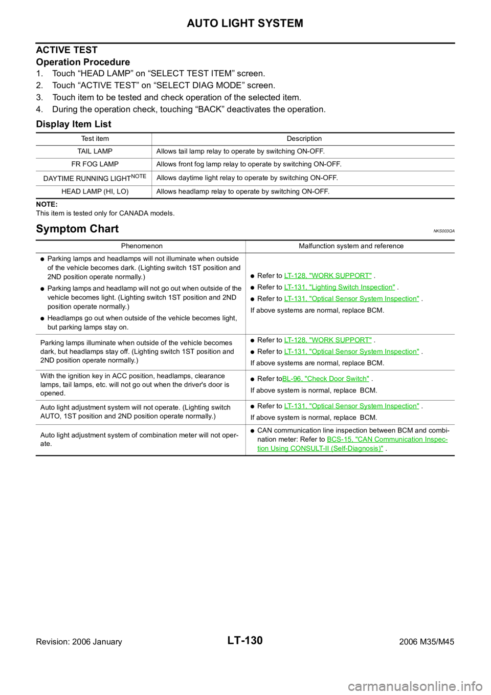
ACTIVE TEST
Operation Procedure
1. Touch “HEAD LAMP” on “SELECT TEST ITEM” screen.
2. Touch “ACTIVE TEST” on “SELECT DIAG MODE” screen.
3. Touch item to be tested and check operation of the selected item.
4. During the operation check, touching “BACK” deactivates the operation.
Display Item List
NOTE:
This item is tested only for CANADA models.
Symptom ChartNKS003QA
Test item Description
TAIL LAMP Allows tail lamp relay to operate by switching ON-OFF.
FR FOG LAMP Allows front fog lamp relay to operate by switching ON-OFF.
DAYTIME RUNNING LIGHT
NOTEAllows daytime light relay to operate by switching ON-OFF.
HEAD LAMP (HI, LO) Allows headlamp relay to operate by switching ON-OFF.
Phenomenon Malfunction system and reference
Parking lamps and headlamps will not illuminate when outside
of the vehicle becomes dark. (Lighting switch 1ST position and
2ND position operate normally.)
Parking lamps and headlamp will not go out when outside of the
vehicle becomes light. (Lighting switch 1ST position and 2ND
position operate normally.)
Headlamps go out when outside of the vehicle becomes light,
but parking lamps stay on.
Refer to LT-128, "WORK SUPPORT" .
Refer to LT-131, "Lighting Switch Inspection" .
Refer to LT-131, "Optical Sensor System Inspection" .
If above systems are normal, replace BCM.
Parking lamps illuminate when outside of the vehicle becomes
dark, but headlamps stay off. (Lighting switch 1ST position and
2ND position operate normally.)
Refer to LT-128, "WORK SUPPORT" .
Refer to LT-131, "Optical Sensor System Inspection" .
If above systems are normal, replace BCM.
With the ignition key in ACC position, headlamps, clearance
lamps, tail lamps, etc. will not go out when the driver's door is
opened.
Refer toBL-96, "Check Door Switch" .
If above system is normal, replace BCM.
Auto light adjustment system will not operate. (Lighting switch
AUTO, 1ST position and 2ND position operate normally.)
Refer to LT-131, "Optical Sensor System Inspection" .
If above system is normal, replace BCM.
Auto light adjustment system of combination meter will not oper-
ate.
CAN communication line inspection between BCM and combi-
nation meter: Refer to BCS-15, "
CAN Communication Inspec-
tion Using CONSULT-II (Self-Diagnosis)" .
Page 4558 of 5621
AUTO LIGHT SYSTEM
LT-131
C
D
E
F
G
H
I
J
L
MA
B
LT
Revision: 2006 January2006 M35/M45
Lighting Switch InspectionNKS003QB
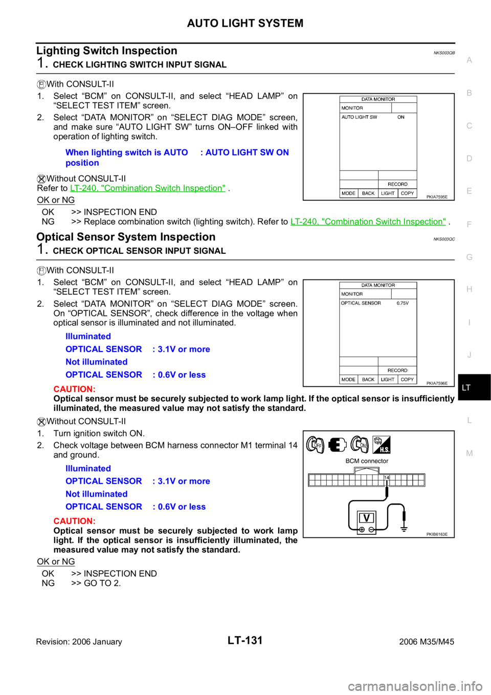
1. CHECK LIGHTING SWITCH INPUT SIGNAL
With CONSULT-II
1. Select “BCM” on CONSULT-II, and select “HEAD LAMP” on
“SELECT TEST ITEM” screen.
2. Select “DATA MONITOR” on “SELECT DIAG MODE” screen,
and make sure “AUTO LIGHT SW” turns ON–OFF linked with
operation of lighting switch.
Without CONSULT-II
Refer to LT-240, "
Combination Switch Inspection" .
OK or NG
OK >> INSPECTION END
NG >> Replace combination switch (lighting switch). Refer to LT- 2 4 0 , "
Combination Switch Inspection" .
Optical Sensor System InspectionNKS003QC
1. CHECK OPTICAL SENSOR INPUT SIGNAL
With CONSULT-II
1. Select “BCM” on CONSULT-II, and select “HEAD LAMP” on
“SELECT TEST ITEM” screen.
2. Select “DATA MONITOR” on “SELECT DIAG MODE” screen.
On “OPTICAL SENSOR”, check difference in the voltage when
optical sensor is illuminated and not illuminated.
CAUTION:
Optical sensor must be securely subjected to work lamp light. If the optical sensor is insufficiently
illuminated, the measured value may not satisfy the standard.
Without CONSULT-II
1. Turn ignition switch ON.
2. Check voltage between BCM harness connector M1 terminal 14
and ground.
CAUTION:
Optical sensor must be securely subjected to work lamp
light. If the optical sensor is insufficiently illuminated, the
measured value may not satisfy the standard.
OK or NG
OK >> INSPECTION END
NG >> GO TO 2.When lighting switch is AUTO
position: AUTO LIGHT SW ON
PKIA7595E
Illuminated
OPTICAL SENSOR : 3.1V or more
Not illuminated
OPTICAL SENSOR : 0.6V or less
Illuminated
OPTICAL SENSOR : 3.1V or more
Not illuminated
OPTICAL SENSOR : 0.6V or less
PKIA7596E
PKIB6163E
Page 4559 of 5621
LT-132
AUTO LIGHT SYSTEM
Revision: 2006 January2006 M35/M45
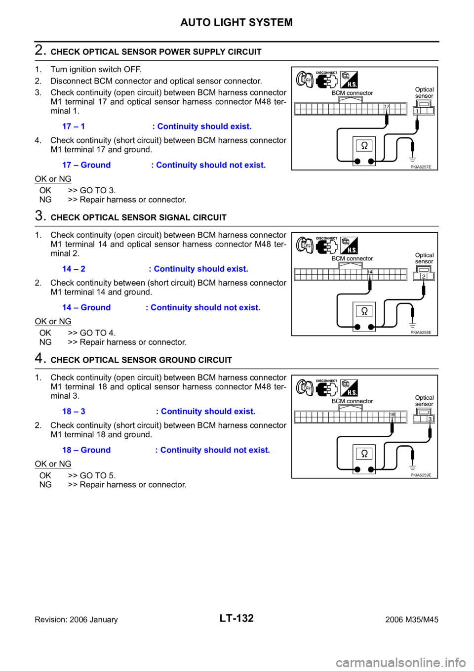
2. CHECK OPTICAL SENSOR POWER SUPPLY CIRCUIT
1. Turn ignition switch OFF.
2. Disconnect BCM connector and optical sensor connector.
3. Check continuity (open circuit) between BCM harness connector
M1 terminal 17 and optical sensor harness connector M48 ter-
minal 1.
4. Check continuity (short circuit) between BCM harness connector
M1 terminal 17 and ground.
OK or NG
OK >> GO TO 3.
NG >> Repair harness or connector.
3. CHECK OPTICAL SENSOR SIGNAL CIRCUIT
1. Check continuity (open circuit) between BCM harness connector
M1 terminal 14 and optical sensor harness connector M48 ter-
minal 2.
2. Check continuity between (short circuit) BCM harness connector
M1 terminal 14 and ground.
OK or NG
OK >> GO TO 4.
NG >> Repair harness or connector.
4. CHECK OPTICAL SENSOR GROUND CIRCUIT
1. Check continuity (open circuit) between BCM harness connector
M1 terminal 18 and optical sensor harness connector M48 ter-
minal 3.
2. Check continuity (short circuit) between BCM harness connector
M1 terminal 18 and ground.
OK or NG
OK >> GO TO 5.
NG >> Repair harness or connector.17 – 1 : Continuity should exist.
17 – Ground : Continuity should not exist.
PKIA6257E
14 – 2 : Continuity should exist.
14 – Ground : Continuity should not exist.
PKIA6258E
18 – 3 : Continuity should exist.
18 – Ground : Continuity should not exist.
PKIA6259E
Page 4560 of 5621
AUTO LIGHT SYSTEM
LT-133
C
D
E
F
G
H
I
J
L
MA
B
LT
Revision: 2006 January2006 M35/M45
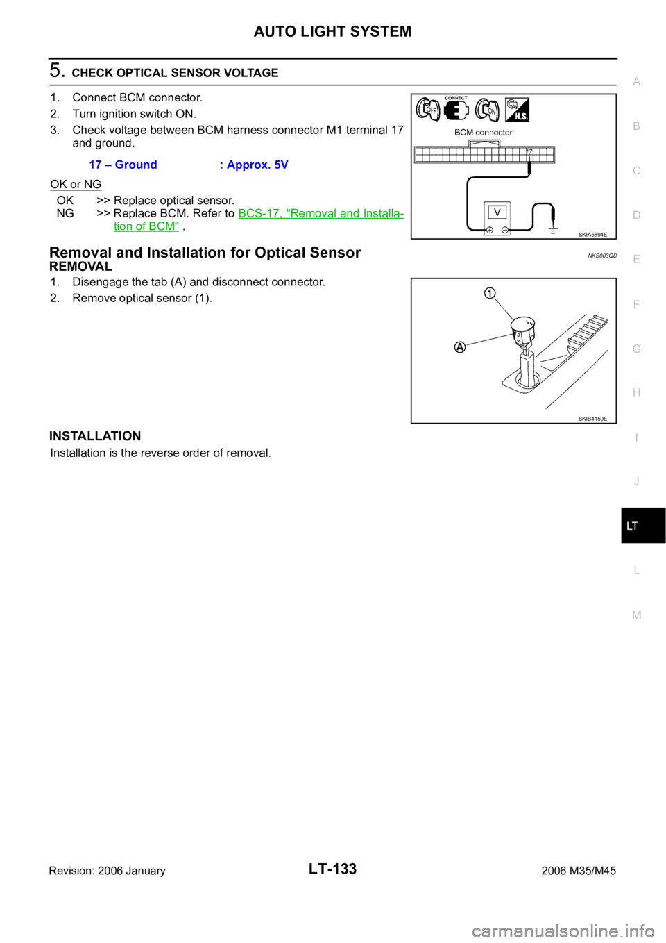
5. CHECK OPTICAL SENSOR VOLTAGE
1. Connect BCM connector.
2. Turn ignition switch ON.
3. Check voltage between BCM harness connector M1 terminal 17
and ground.
OK or NG
OK >> Replace optical sensor.
NG >> Replace BCM. Refer to BCS-17, "
Removal and Installa-
tion of BCM" .
Removal and Installation for Optical SensorNKS003QD
REMOVAL
1. Disengage the tab (A) and disconnect connector.
2. Remove optical sensor (1).
INSTALLATION
Installation is the reverse order of removal.17 – Ground : Approx. 5V
SKIA5894E
SKIB4159E
Page 4565 of 5621
LT-138
ACTIVE AFS
Revision: 2006 January2006 M35/M45
through front combination lamp RH terminal 21.
Swivel position sensor detects swivel angle during ignition switch ON, and transmits swivel position sensor
signals to the AFS control unit:
When ignition switch is turn to ON position, power is supplied
to front combination lamp RH terminal 15
through AFS control unit terminal 4.
When ignition switch is turn to ON position, swivel position sensor input signal is supplied
to AFS control unit terminal 9
through front combination lamp RH terminal 14.
Ground is supplied
to front combination lamp RH terminal 19
through AFS control unit terminal 2.
The low beam headlamp RH starts to swivel to the right.
The swivel motor driving signals are blocked and the swivel motion stops when the steering angle reaches
approximately more than 80 degrees (predetermined). The low beam headlamp will not swivel any further no
matter how further right. As the steering wheel is turned back to the left, the swivel motor driving signals (both
1-phase and 2-phase) will be reversed, causing low beam headlamp RH to start swiveling to the left. When
steering angle becomes smaller than predetermined value, the low beam headlamp is set in the straight-
ahead position, swivel motor driving signals are blocked and low beam headlamps stop swiveling.
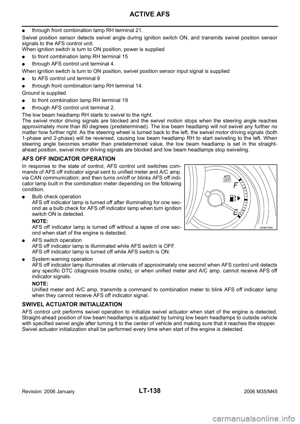
AFS OFF INDICATOR OPERATION
In response to the state of control, AFS control unit switches com-
mands of AFS off indicator signal sent to unified meter and A/C amp.
via CAN communication; and then turns on/off or blinks AFS off indi-
cator lamp built in the combination meter depending on the following
condition.
Bulb check operation
AFS off indicator lamp is turned off after illuminating for one sec-
ond as a bulb check for AFS off indicator lamp when turn ignition
switch ON is detected.
NOTE:
AFS off indicator lamp is turned off without a lapse of one sec-
ond when start of the engine is detected.
AFS switch operation
AFS off indicator lamp is illuminated while AFS switch is OFF.
AFS off indicator lamp is turned off while AFS switch is ON.
System warning operation
AFS off indicator lamp illuminates at intervals of approximately one second when AFS control unit detects
any specific DTC (diagnosis trouble code), or when unified meter and A/C amp. cannot receive AFS off
indicator signals.
NOTE:
Unified meter and A/C amp. transmits a command to combination meter to blink AFS off indicator lamp
when they cannot receive AFS off indicator signal.
SWIVEL ACTUATOR INITIALIZATION
AFS control unit performs swivel operation to initialize swivel actuator when start of the engine is detected.
Straight-ahead position of low beam headlamps is adjusted by turning low beam headlamps to outside vehicle
with specified swivel angle after turning it to the center of vehicle and making sure that it reaches the stopper.
Swivel actuator initialization shall be performed every time when start of the engine is detected.
SKIB4765E
Page 4578 of 5621
ACTIVE AFS
LT-151
C
D
E
F
G
H
I
J
L
MA
B
LT
Revision: 2006 January2006 M35/M45
How to Proceed with Trouble DiagnosisNKS003QK
1. Confirm the symptom or customer complaint.
2. Understand operation description and function description. Refer to LT-135, "
System Description" .
3. Perform the preliminary check. Refer to LT- 1 5 1 , "
Preliminary Check" .
4. Perform self-diagnosis by CONSULT-II. Refer to LT-154, "
SELF-DIAG RESULTS" .
5. Check symptom and repair or replace the cause of malfunction.
6. Does the swivel control operate normally? If YES: GO TO 7. If NO: GO TO 4.
7. INSPECTION END
Preliminary CheckNKS003QL
1. CHECK FUSE
Check for blown fuses.
Refer to LT-143, "Wiring Diagram — AFS —" .
OK or NG
OK >> GO TO 2.
NG >> If the fuse is brown be sure to eliminate cause of malfunction before installing new fuse. Refer to
PG-3, "
POWER SUPPLY ROUTING CIRCUIT" .
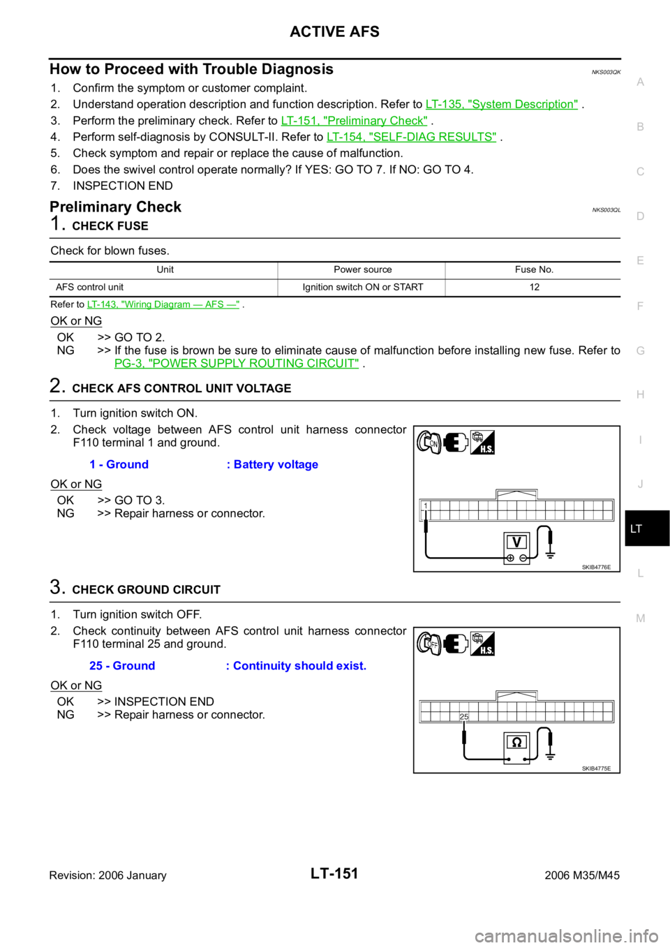
2. CHECK AFS CONTROL UNIT VOLTAGE
1. Turn ignition switch ON.
2. Check voltage between AFS control unit harness connector
F110 terminal 1 and ground.
OK or NG
OK >> GO TO 3.
NG >> Repair harness or connector.
3. CHECK GROUND CIRCUIT
1. Turn ignition switch OFF.
2. Check continuity between AFS control unit harness connector
F110 terminal 25 and ground.
OK or NG
OK >> INSPECTION END
NG >> Repair harness or connector.
Unit Power source Fuse No.
AFS control unit Ignition switch ON or START 12
1 - Ground : Battery voltage
SKIB4776E
25 - Ground : Continuity should exist.
SKIB4775E
Page 4579 of 5621
LT-152
ACTIVE AFS
Revision: 2006 January2006 M35/M45
CONSULT-II Function (ADAPTIVE LIGHT)NKS003QM
CONSULT-II can display each diagnostic item using diagnostic test modes shown following.
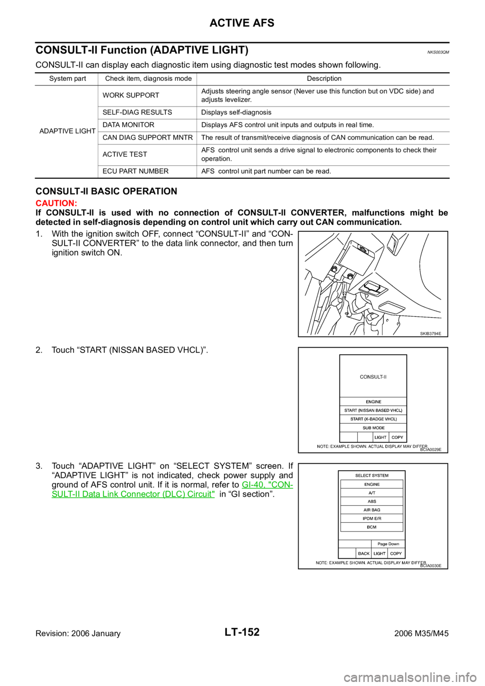
CONSULT-II BASIC OPERATION
CAUTION:
If CONSULT-II is used with no connection of CONSULT-II CONVERTER, malfunctions might be
detected in self-diagnosis depending on control unit which carry out CAN communication.
1. With the ignition switch OFF, connect “CONSULT-II” and “CON-
SULT-II CONVERTER” to the data link connector, and then turn
ignition switch ON.
2. Touch “START (NISSAN BASED VHCL)”.
3. Touch “ADAPTIVE LIGHT” on “SELECT SYSTEM” screen. If
“ADAPTIVE LIGHT” is not indicated, check power supply and
ground of AFS control unit. If it is normal, refer to GI-40, "
CON-
SULT-II Data Link Connector (DLC) Circuit" in “GI section”.
System part Check item, diagnosis mode Description
ADAPTIVE LIGHTWORK SUPPORTAdjusts steering angle sensor (Never use this function but on VDC side) and
adjusts levelizer.
SELF-DIAG RESULTS Displays self-diagnosis
DATA MONITOR Displays AFS control unit inputs and outputs in real time.
CAN DIAG SUPPORT MNTR The result of transmit/receive diagnosis of CAN communication can be read.
ACTIVE TESTAFS control unit sends a drive signal to electronic components to check their
operation.
ECU PART NUMBER AFS control unit part number can be read.
SKIB3794E
BCIA0029E
BCIA0030E
Page 4581 of 5621

LT-154
ACTIVE AFS
Revision: 2006 January2006 M35/M45
7. Touch “END”.
8. Turn ignition switch OFF.
SELF-DIAG RESULTS
Operation Procedure
1. Touch “ADAPTIVE LIGHT” on “SELECT SYSTEM” screen.
2. Touch “SELF-DIAG RESULTS” on the “SELECT DIAG MODE” screen.
3. Check display content in self-diagnostic results.
CAUTION:
DTC B2503 and B2504 cannot be detected before the swivel operation. Thus, perform swivel operation
first, and then check the display in self-diagnostic results.
Description of DTC and Solutions after Detection
CONSULT-II can detect DTC (Diagnosis trouble code). The descriptions and solutions of DTC are listed
below.
Details of
error
indication
detected by
CONSULT-
IIConditions of error detectionFail-safe
1. Swivel operation
2. Auto aiming operation
3. AFS OFF indicator operation
4. CancellationReference
CAN
COMM CIR-
CUIT
[U1000]Any of several items below have errors.
TRANSMIT DIAG
Reception from ECM
Reception from unified meter and A/C amp.
Reception from TCM
Reception from steering angle sensor
Reception from IPDM E/R1. Stop the swivel motor RH and
LH when the malfunction
occurred.
2. Stop the aiming motors when the
malfunction occurred.
3. Flash at intervals of approx. 1
second when keeping error state
for 2 seconds or longer.
4. Turn ignition switch OFF.LAN-9,
"TROUBLE
DIAGNOSES
WORK
FLOW" i n L A N
section.
CONTROL
UNIT (CAN)
[U1010]AFS control unit malfunctions.1. Stop the swivel motor RH and
LH when the malfunction
occurred.
2. Stop aiming motors when the
malfunction occurred.
3. Flash at intervals of approx. 1
second when keeping error state
for 2 seconds or longer.
4. Turn ignition switch OFF.Replace
AFS control
unit. LT- 1 9 1